Purpose and functions of the node
Water in centralized heating networks reaches a temperature of 150 °C and moves through external pipelines under a pressure of 6-10 bar. Why are such high coolant parameters maintained:
- So that high-temperature boilers or other thermal power equipment operate with maximum efficiency.
- To deliver heated water to areas remote from the boiler house or thermal power plant, network pumps must create a decent pressure. Then at the thermal inputs of nearby buildings the pressure reaches 10 Bar (pressure testing - 12 Bar).
- Transportation of superheated coolant is economically beneficial. A ton of water brought to 150 degrees contains significantly more thermal energy than a similar volume at 90 ° C.
Reference. The coolant in the pipes does not turn into steam, since it is under pressure, keeping the water in a liquid aggregate state.
The part is simple - it looks like an ordinary tee with flanges
. According to current regulatory documents, the temperature of the coolant supplied to the water heating system of a residential or administrative building should not exceed 95 ° C. And the pressure of 8-10 atmospheres is too high for an intra-house heating network. This means that the specified water parameters need to be adjusted downward.
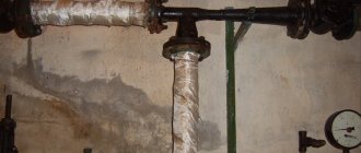
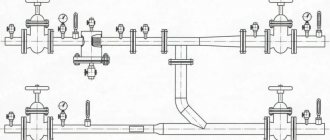
An elevator is a non-volatile device that lowers the pressure and temperature of the incoming coolant by mixing cooled water coming from the heating system. The element shown in the photo above is part of the thermal unit circuit and is installed between the supply and return pipelines.
The third function of the elevator is to ensure the circulation of water in the house circuit (usually a single-pipe system). That is why this element is of interest - despite its apparent simplicity, it combines 3 devices - a pressure regulator, a mixing unit and a water-jet circulation pump.
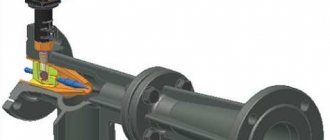
Elevator element with replaceable nozzle
Stages of washer heating system
- Hydraulic calculation of the heating system, calculation of washers
- Development of recommendations for improving the operation of the heating station and heating system
- Installation of control washers on risers (the customer can carry out this work independently)
- Checking the implementation of recommended measures
- Analysis of the new steady state after washing the heating system
- Adjusting the size of washers in places where the required result has not been achieved (by calculation)
- Removing washers that require adjustment, installing new washers
On internal heating systems, washers can be installed in both winter and summer. Check their operation only during the heating season.
The principle of operation of the elevator
Externally, the design resembles a large tee made of metal pipes with connecting flanges at the ends. How the elevator works inside:
- the left nozzle (see drawing) is a tapering nozzle of the calculated diameter;
- behind the nozzle there is a cylindrical mixing chamber;
- the lower pipe is used to connect the return line to the mixing chamber;
- the right pipe is an expanding diffuser that directs coolant into the heating network of a multi-story building.
In the drawing, the ejected flow pipe is conventionally shown at the top, although it is usually located at the bottom
Note. In the classic version, the elevator does not require connection to the house electrical network. An updated version of the product with an adjustable nozzle and an electric drive is connected to an external power source.
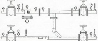
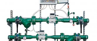
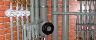
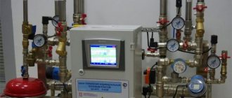
The steel elevator unit is connected by the left branch pipe to the supply line of the centralized heating network, and by the bottom branch pipe to the return pipeline. Shut-off valves are installed on both sides of the element, plus a mesh filter - a sump (otherwise known as a sludge tank) on the supply. The traditional scheme of a heating point with an elevator also includes pressure gauges, thermometers (on both lines) and a meter for energy consumption.
Now let's look at how the elevator jumper works:
- Superheated water from the heating network passes through the left pipe to the nozzle.
- At the moment of passing through the narrow section of the nozzle under high pressure, the flow accelerates according to Bernoulli's law. The effect of a water jet pump begins to operate, ensuring the circulation of coolant in the system.
- In the area of the mixing chamber, the water pressure decreases to normal.
- The jet moving at high speed into the diffuser creates a vacuum in the mixing chamber. An ejection effect occurs - a flow of liquid with a higher pressure entrains the coolant returning from the heating network through the jumper.
- In the heating elevator chamber, the cooled water is mixed with superheated water, and at the outlet of the diffuser we obtain the coolant at the required temperature (up to 95 °C).
Clarification. It is worth noting that the elevator unit also uses the injection principle in its operation - mixing two jets with simultaneous transfer of energy. The pressure of the resulting flow becomes less than the initial one, but more than that sucked from the return. The process is shown more clearly in the video:
The main condition for normal operation of the elevator is a sufficient pressure difference between the main supply and the return line. This difference should be enough to overcome the hydraulic resistance of the home heating system and the injector itself. Please note: the vertical jumper cuts into the return at an angle of 45° for better flow separation.
At the supply from the heating network, the pressure is highest, at the outlet from the diffuser - average, in the return line - the lowest. The same thing happens in the elevator with water temperature
Control
The controlling organization is, again, heating networks.
What exactly do they control?
- Several times during the winter, control measurements are taken of the temperatures and pressures of the supply, return and mixture
. In case of deviations from the temperature curve, the calculation of the heating elevator is carried out again with boring or reducing the diameter of the nozzle. Of course, this should not be done during the peak of cold weather: at -40 outside, the access heating system can become covered with ice within an hour after the circulation stops. - In preparation for the heating season, the condition of the shut-off valves is checked
. The check is extremely simple: all valves in the assembly are closed, after which any control valve opens. If water comes from it, you need to look for a fault; In addition, in any position of the valves, they should not have leaks through the seals. - Finally, at the end of the heating season, the elevators in the heating system, along with the system itself, are tested for temperature. When the DHW supply is turned off, the coolant heats up to maximum values.
Technical characteristics of standard products
The line of factory-made elevators consists of 7 standard sizes, each assigned a number. When selecting, 2 main parameters are taken into account - the diameter of the neck (mixing chamber) and the working nozzle. The latter is a removable cone, which can be changed if necessary.
See the table below for the dimensions of the component elements of the product.
The nozzle is replaced in two cases:
- When the flow area of a part increases as a result of natural wear. The reason for the development is the friction of abrasive particles contained in the coolant.
- If it is necessary to change the mixing coefficient, increase or decrease the temperature of the water supplied to the house heating system.
The numbers of standard elevators and main dimensions are given in the table (compare with the designations on the drawing).
Please note: the technical specifications do not indicate the nozzle flow area, since this diameter is calculated separately. To select the number of the finished elevator tee for a specific heating system, it is also necessary to calculate the required size of the mixing and injection chamber.
Operating principle
The best example that will show the operating principle of a heating elevator would be a multi-storey building. It is in the basement of a multi-story building that you can find an elevator among all the elements.
First of all, let's look at the drawing of the elevator heating unit in this case. There are two pipelines: supply (it is through it that hot water goes to the house) and return (cooled water returns to the boiler room).
Diagram of an elevator heating unit
From the thermal chamber, water enters the basement of the house; there is always a shut-off valve at the entrance. Usually these are valves, but sometimes in those systems that are more thought out, steel ball valves are installed.
As the standards show, there are several thermal regimes in boiler rooms:
- 150/70 degrees;
- 130/70 degrees;
- 95(90)/70 degrees.
When the water heats up to a temperature no higher than 95 degrees, the heat will be distributed throughout the heating system using a collector. But at temperatures above normal - above 95 degrees, everything becomes much more complicated. Water at this temperature cannot be supplied, so it must be reduced. This is precisely the function of the elevator heating unit. We also note that cooling water in this way is the simplest and cheapest way.
Calculation and selection of elevator by number
Let’s immediately clarify the procedure: first of all, the diameter of the mixing chamber is calculated and the appropriate elevator number is selected, then the size of the working nozzle is determined. The diameter of the injection chamber (in centimeters) is calculated by the formula:
The indicator Gpr participating in the formula is the real coolant flow rate in the system of an apartment building, taking into account its hydraulic resistance. The value is calculated as follows:
- Q – amount of heat consumed to heat the building, kcal/h;
- Tcm is the temperature of the mixture at the outlet of the elevator tee;
- Т2о – water temperature in the return line;
- h is the resistance of the entire heating wiring together with radiators, expressed in meters of water column.
Reference. To insert unknown kilocalories into the formula, you need to multiply the familiar watts by a factor of 0.86. Meters of water column are converted to the more common units: 10.2 m water. Art. = 1 Bar.
An example of selecting an elevator number. We found out that the actual consumption Gpr will be 10 tons of mixed water in 1 hour. Then the diameter of the mixing chamber is 0.874 √10 = 2.76 cm. It is logical to take mixer No. 4 with a 30 mm chamber.
Now we find out the diameter of the narrow part of the nozzle (in millimeters) using the following formula:
- Dr – previously determined size of the injection chamber, cm;
- u – mixing coefficient;
- Gpr is our consumption of the finished coolant when supplied to the system.
Although the formula seems cumbersome on the surface, in reality the calculations are not too complicated. One parameter remains unknown - the injection coefficient, calculated as follows:
We have deciphered all the designations from this formula, except for parameter T1 - the temperature of hot water at the entrance to the elevator. If we assume that its value is 150 degrees, and the supply and return temperatures are 90 and 70 °C, respectively, the required size Dc will be 8.5 mm (at a flow rate of 10 t/h of water).
When the pressure value Нр at the entrance to the elevator from the central side is known, you can use an alternative formula for determining the diameter:
Comment. The result of the calculation using the last formula is expressed in centimeters.
Results
In this article we found out what an elevator is in a heating system, what it consists of and how it works. As it turned out, such equipment is widespread due to its undeniable advantages. There is no reason for utility companies to abandon them.
There are alternatives for this equipment, but they are distinguished by their high cost, lower reliability and energy efficiency, because they require electricity and periodic repairs to operate.
The main design characteristic for an elevator is the mixing coefficient U, which determines the ratio of the chilled water flow rate of the system to the hot water flow rate of the heating network:
where: tc – temperature of the heating network water, o C;
tr – temperature of hot water of the heating system, o C;
to – temperature of the chilled water of the heating system, o C.
To select an elevator, we determine the pressure created by the pump ∆p us, Pa, using the formula:
. (20)
where p e is the available pressure in the heating network at the entrance to the building in front of the elevator.
The diameter of the elevator neck (mixing chamber) dr, mm, is determined by the formula:
. (21)
where Gс is the estimated flow rate of network water, kg/h.
. (22)
where: c – heat capacity of water equal to 4.18 kJ/(kg* 0 C);
β 1 – correction factor taking into account the additional heat flow of installed OPs due to rounding above the calculated value (β 1 = 1.05);
β 2 is a correction factor that takes into account additional heat loss from external enclosures (β 2 =1.02).
Using formula (19), we determine the mixing coefficient, for which tr = 95 o C, tc = 130 o C, to = 70 o C
U = (130-95)/(95-70) =1.4;
We determine the pressure created by the pump using formula (20), for which p e =120 kPa
∆p us = 120/(1.4*(1+1.4) 2)=14.88 kPa;
The estimated flow rate of network water is determined by formula (22) for which β 1 =1.05, β 2 =1.02.
The diameter of the elevator neck (mixing chamber) is determined by formula (21):
mm.
According to Table 1, we select elevator No. 5 with a mixing chamber diameter of 35 mm and a length of 625 mm.
5 Hydraulic calculation of a water heating system
We carry out a hydraulic calculation of a water heating system to determine the diameters of heat pipes at a given thermal load and calculated circulation pressure. The calculation is made using the method of average specific losses.
Initially, we select the main circulation ring passing through the upper heating device of the distant riser. We determine the average value of the specific pressure drop along the main circulation ring:
, (24)
where K is a coefficient that takes into account the share of pressure loss due to local resistance (for systems with artificial circulation k = 0.35);
l – total length of design sections, m.
pc – calculated circulation pressure (assumed equal to p us (formula 20))
We determine the water consumption of the design sections G uch, kg/h:
, (25)
where Q is the thermal load of the area, composed of the thermal loads of heating devices, W;
C – heat capacity of water – 4.18 kJ/(kgС);
t 2 - t 0 – temperature difference in the system, С
Focusing on R beat avg and G uch, using Appendix Table 6, we select the actual diameter of the section d and the value of the specific pressure loss due to friction in each section, multiplying R beat f with the length of the section.
We find the pressure loss due to local resistance:
, (26)
where P d – dynamic pressure value, Pa (Appendix 7, page 457),
—local resistance coefficient (Appendix 5).
The local resistance of tees and crosses is attributed to design areas with lower water consumption; the local resistance of heating devices is taken into account equally in each pipeline adjacent to them.
Total pressure losses in the area for selected diameters:
, (27)
Next, we sum up all the losses in the ring, and the resulting number should be in the range of (0.9 - 0.95) P c available pressure in the ring. If this condition is not met, then it is necessary to recalculate the sections until the condition is met.
We enter the data in table 5.1
Table 5.1 - Calculation sheet for ventilation ducts
| According to the pipeline diagram | According to preliminary calculation | |||||||||
| Plot number | Water consumption in area G, kg/h | Section length l, m | Diameter d, mm | Water speed W, m/s | Specific pressure loss Rsrud, Pa/m | Friction pressure loss Rfu*l, Pa | Sum coefficient local resistance.åx | Pressure loss in local resistances. Z,Pa | Total pressure loss (Rfud*l+Z),.Pa | |
| Pc=0.9*120=108kPa>45.05kPa | ||||||||||
6 Design and calculation of exhaust ventilation
.
We equip the residential building with natural duct exhaust ventilation. The amount of air removed must be at least 3m3/h per 1m2 of living space. We remove air through grilles located 0.5 m below the ceiling. According to fire safety rules, rooms located on different floors are not connected to the same exhaust duct. The movement of air in the air duct occurs due to the difference in pressure inside the room and outside at the outlet of the air duct; called available pressure, defined as:
, (28)
where h is the height, in meters, of the air column from the middle of the exhaust hole to the mouth of the shaft;
n - density of outside air at t n = 5С ( n -1.27 kg/m 3);
in - air density of the ventilated room at 18С ( in = 1.21 kg/m 3).
We take the ventilation duct of the upper floor as the design branch, as it is closest to the mouth of the shaft.
We preliminarily determine the cross-sectional area of the channel F, m 2, using the formula:
, (29)
where W is the air speed in the channel, m/s.
L-air exchange of the ventilated room, m 3 /h.
, (30)
We recalculate the rectangular channel to the equivalent diameter d e, m, using the formula:
, (31)
where a and b are the dimensions of the sides of the rectangular air duct, mm.
Based on the value of W and d e using a nomogram, we determine the value of resistivity R, Pa/m. Pressure loss in the ventilation branch p sweat, Pa, is determined as the sum of pressure losses due to friction and local resistance:
where l is the length of the section branch, m;
—roughness coefficient (Table A17);
- the sum of the local resistance coefficients on the site, determined based on table A18;
p - dynamic pressure, Pa, determined by the nomogram (Figure A2.
The amount of pressure loss must be equal to or less than the available pressure. If the deviation in pressure loss is more than 10%, it is necessary to change the dimensions of the channel cross-section. We record the measurement results in Table 6.1.
Lk=90
Lcy(2)=50
Lsy(1)=25+25=50 m 3 /h.
| Table 6.1 - Calculation sheet for ventilation ducts | ||||||||||||
| Plot number | Air flow L, m 3 / h | Section length l, m | Air duct size ab, mm | Air duct cross-sectional area F, m2 | Equivalent diameter d e, mm | Air speed W, m/s | Specific pressure loss R, Pa/m | Friction pressure loss R*l * β, Pa | Dynamic pressure P d, Pa | Sum of local resistance coefficients | Pressure loss in local resistances * P d, Pa | Total pressure loss P sweat, Pa |
| Δр=7.4*9.8(1.27-1.21)=4.35Pa | ||||||||||||
The heating system is one of the most important life support systems at home. Every home uses a certain heating system, but not every user knows what an elevator heating unit is and how it works, its purpose and the opportunities that are provided with its use.
Heating elevator with electric drive
Switchgears
The elevator unit with all its piping can be thought of as a pressure circulation pump, which supplies coolant to the heating system under a certain pressure.
If the facility has several floors and consumers, then the most correct solution is to distribute the total coolant flow to each consumer.
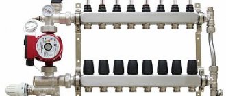
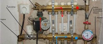
To solve such problems, a comb is designed for the heating system, which has another name - a collector. This device can be represented as a container. The coolant flows into the container from the elevator outlet, which then flows out through several outlets, with the same pressure.
Consequently, the distribution comb of the heating system allows the shutdown, adjustment, and repair of individual consumers of the facility without stopping the operation of the heating circuit. The presence of a collector eliminates the mutual influence of the heating system branches. In this case, the pressure in corresponds to the pressure at the elevator outlet.
