The elevator unit is specialized equipment located in the thermal distribution center. The main tasks of this device are: increasing the volume of heated water, reducing its pressure and t, as well as pumping. The operation of conventional elevators is adjusted by reducing or increasing the size of the component parts. There are also mechanically and electrically adjustable elevators.
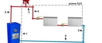
The functioning of the heating system schematically Source elevator66.ru
Heating system design
A thermal unit is a way to connect a home heating system to the main networks.
The structure of the heating unit in a typical Soviet-era apartment building includes: a mud trap, shut-off valves, control devices, the elevator itself, etc. The elevator unit is placed in a separate ITP room (individual heating point). There must certainly be shut-off valves in order to, if necessary, disconnect the intra-house system from the main heat supply. In order to avoid blockages and blockages in the system itself and in the devices of the internal house pipeline, it is necessary to isolate the dirt coming along with hot water from the main heating network; for this purpose, a mud trap is installed. The diameter of the mud trap is usually from 159 to 200 millimeters; all incoming dirt (solid particles, scale) collects and settles in it. The mud trap, in turn, needs timely and regular cleaning.
Control devices mean thermometers and pressure gauges that measure temperature and pressure in the elevator unit.
How to serve
The operation of the elevator is based on the action of physical laws, therefore its design does not provide for any moving or rotating parts. Even in more complex designs with a changing nozzle size, a special needle moves, increasing or decreasing the passage for the coolant (based on the principle of a spray gun), which does not have a high movement speed. Therefore, all maintenance of the device consists of timely cleaning of dirt, removing dirt that gradually accumulates due to the low quality of the coolant. Nozzles are subject to periodic replacement; they are subject to stress when exposed to a flow of hot water and are the first to fail. The diameter and condition of the nozzle are checked annually, replacement is carried out when the need arises - severe wear of the part, excessive increase or decrease in throughput. It is also necessary to monitor the tightness of flange connections and change gaskets and seals in a timely manner.
Design and principle of operation of a heating elevator
At the entry point of the heating network pipeline, usually in the basement, a node that connects the supply and return pipes catches your eye. This is an elevator - a mixing unit for heating a house. The elevator is manufactured in the form of a cast iron or steel structure equipped with three flanges. This is an ordinary heating elevator; its operating principle is based on the laws of physics. Inside the elevator there is a nozzle, a receiving chamber, a mixing neck and a diffuser. The receiving chamber is connected to the “return” using a flange.
Superheated water enters the elevator inlet and passes into the nozzle. Due to the narrowing of the nozzle, the flow speed increases and the pressure decreases (Bernoulli's law). Water from the return line is sucked into the area of low pressure and mixed in the mixing chamber of the elevator. The water reduces the temperature to the desired level and at the same time the pressure decreases. The elevator operates simultaneously as a circulation pump and mixer. This is briefly the principle of operation of an elevator in the heating system of a building or structure.
Thermal unit diagram
Adjustment of the coolant supply is carried out by the elevator heating units of the house. The elevator is the main element of the heating unit and needs piping. The control equipment is sensitive to contamination, so the piping includes dirt filters that are connected to the “supply” and “return”.
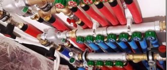
The elevator harness includes:
- mud filters;
- pressure gauges (inlet and outlet);
- temperature sensors (thermometers at the elevator inlet, outlet and return);
- valves (for preventive or emergency work).
This is the simplest circuit option for adjusting the temperature of the coolant, but it is often used as the basic device of a thermal unit. The basic elevator heating unit for any buildings and structures provides regulation of the temperature and pressure of the coolant in the circuit.
The advantages of using it for heating large objects, houses and high-rise buildings:
- reliability due to the simplicity of the design;
- low cost of installation and components;
- absolute energy independence;
- significant savings in coolant consumption up to 30%.
But while there are undeniable advantages of using an elevator for heating systems, the disadvantages of using this device should also be noted:
- the calculation is done individually for each system;
- a mandatory pressure drop is required in the heating system of the facility;
- if the elevator is unregulated, then it is impossible to change the parameters of the heating circuit.
Elevator with automatic adjustment
Currently, elevator designs have been created in which the nozzle cross-section can be changed using electronic adjustment. This elevator has a mechanism that moves the throttle needle. It changes the lumen of the nozzle and as a result the coolant flow changes. Changing the lumen changes the speed of water movement. As a result, the mixing ratio of hot water and water from the “return” changes, thereby achieving a change in the temperature of the coolant in the “supply”. Now it’s clear why water pressure is needed in a heating system.
The elevator regulates the flow and pressure of the coolant, and its pressure drives the flow in the heating circuit.
Installation of an elevator into the system
This device is most often located in the basement of the house, but before starting installation-related manipulations, the room is checked for such nuances as:
- No temperature drop below 0 degrees Celsius.
- The room must be covered.
- The presence of exhaust ventilation, since after condensation forms on the pipes, the unit will quickly fail.
Models with built-in automatic mechanisms require an uninterrupted supply of electricity, so without installing an independent power source, such equipment will be unsafe.
When the supply of a resource important for operation is turned off, the temperature control process should not stop, otherwise a lot of unpleasant moments will occur, and to avoid voltage drops, it is necessary to install a condensation rectifier.
Why do you need a thermal unit?
The heating point is located at the entrance of the heating main to the house. Its main purpose is to change the parameters of the coolant. To put it more clearly, the heating unit reduces the temperature and pressure of the coolant before it enters your radiator or convector. This is necessary not only so that you do not get burned from touching the heating device, but also to extend the service life of all heating system equipment
This is especially important if the heating inside the house is installed using polypropylene or metal-plastic pipes. There are regulated operating modes of thermal units:
These figures show the maximum and minimum temperature of the coolant in the heating main.
Also, according to modern requirements, a heat meter must be installed at each heating unit. Now let's move on to the design of thermal units.
Technical characteristics of standard models
Factory copies have 7 types of designs, differing in size, each of them has its own special number. To successfully select a good option and avoid problems during crimping, it is worth considering two parameters - the diameter of the mixing chamber and the nozzle.
With the second component the situation is simpler; it can be replaced if necessary, because the body is removable. Such actions are resorted to in 2 options:
- Wear of a part after a certain time (wear and tear due to abrasive particles).
- Changes in the mixing ratio, which is necessary to increase or decrease the temperature of the coolant.
I learned an interesting fact about the operation of the elevator unit: often in the technical specifications there is no point that introduces the buyer to the nozzle cross-section; the diameter is calculated separately. The main attention is focused on the mixing and injection chamber in order to accurately calculate the size for a specific heating system.
Determining the value of the thermal unit
An elevator is a non-volatile independent device that performs the functions of water-jet pumping equipment. The heating unit lowers the pressure and temperature of the coolant by mixing in cooled water from the heating system.
The equipment is capable of transmitting coolant heated to the highest possible temperatures, which is beneficial from an economic point of view. A ton of water heated to +150 C has much greater thermal energy than a ton of coolant with a temperature of only +90 C.
Operating principles and detailed diagram of the thermal unit
To understand how the equipment works, you need to understand its structure. The layout of the elevator heating unit is not complicated. The device is a metal tee with connecting flanges at the ends.
The design features are:
- the left nozzle is a nozzle tapered towards the end to the design diameter;
- Behind the nozzle there is a cylindrical mixing chamber;
- the lower pipe is needed to connect the water return circulation pipeline;
- the right pipe is a diffuser with expansion that transports hot coolant into the network.
Despite the simple design of the thermal unit elevator, the operating principle of the unit is much more complex:
- The coolant heated to a high temperature moves through the pipe into the nozzle, then under pressure the transportation speed increases, and the water quickly flows through the nozzle into the chamber. The effect of a water jet pump maintains a given intensity of coolant flow in the system.
- As water passes through the chamber, the pressure decreases and the stream passes through the diffuser, providing a vacuum in the mixing chamber. Then, under high pressure, the coolant moves the liquid returned from the heating line through the jumper. The pressure is created by the ejection effect due to the vacuum, which maintains the flow of the supplied coolant.
- In the mixing chamber, the temperature regime of the flows decreases to +95 C, this is the optimal indicator for transportation through the home heating system.
Understanding what a heating unit is in an apartment building, the principle of operation of an elevator and its capabilities, it is important to maintain the recommended pressure difference in the supply and return pipelines. The difference is necessary to overcome the hydraulic resistance of the network in the house and the device itself
The elevator unit of the heating system is integrated into the network as follows:
- the left pipe is connected to the supply line;
- lower – to pipes with reverse transportation;
- shut-off valves are mounted on both sides and are supplemented with a dirt filter to prevent clogging of the unit.
The entire circuit is equipped with pressure gauges, heat consumption meters, and thermometers. For better flow resistance, the jumper is cut into the return pipeline at an angle of 45 degrees.
Advantages and disadvantages of thermal units
A non-volatile heating elevator is inexpensive, does not need to be connected to a power supply, and works flawlessly with any type of coolant. These properties ensured the demand for equipment in houses with central heating, where a high degree of heating coolant is supplied.
Disadvantages of use:
- Maintaining the differential water pressure in the return and supply pipelines.
- Each line requires specific calculations and parameters of the heating unit. At the slightest change in liquid temperature, you will have to adjust the nozzle holes and install a new nozzle.
- There is no way to smoothly regulate the intensity and heating of the transported coolant.
Units with adjustable flow area by manual or electric drive of a gear transmission located in the antechamber are offered for sale. But in this case, the device loses its energy independence.
Main disadvantages
Despite the fact that the elevator unit has many advantages, it also has one significant drawback. It’s just that the elevator circuit does not provide for the possibility of adjusting the temperature of the outgoing coolant.
If the return water temperature indicates that it is very hot, you will need to reduce it. This problem can only be solved by reducing the size of the nozzle, but this cannot always be done due to the design features of the equipment.
In some cases, the heating unit is equipped with an electric drive, thanks to which the size of the nozzle can be adjusted. It moves the main structural element - the throttle cone needle. This needle moves a certain distance into the hole inside the nozzle. The depth of movement makes it possible to change the diameter of the nozzle and thereby regulate the temperature of the coolant.
Both a manual drive in the form of a handle and a remotely controlled electric motor can be installed on the shaft.
It must be said that the installation of this temperature regulator makes it possible to improve the overall heating system with a thermal unit without significant material costs.
Main malfunctions of the elevator unit
Even such a simple device as an elevator unit may not work correctly. Malfunctions can be determined by analyzing pressure gauge readings at control points of the elevator unit:
- Malfunctions are often caused by pipelines becoming clogged with dirt and solid particles in the water. If there is a pressure drop in the heating system, which is significantly higher before the sump tank, then this malfunction is caused by a clogged sump tank located in the supply pipeline. Dirt is discharged through the drain channels of the mud collector, and the meshes and internal surfaces of the device are cleaned.
- If the pressure in the heating system fluctuates, then possible causes may be corrosion or clogged nozzle. If the nozzle is destroyed, the pressure in the heating expansion tank may exceed the permissible limit.
- It is possible that the pressure in the heating system increases, and the pressure gauges before and after the sump tank in the “return” show different values. In this case, you need to clean the return dirt trap. The drain taps on it are opened, the mesh is cleaned, and contaminants are removed from the inside.
- When the size of the nozzle changes due to corrosion, a vertical misalignment of the heating circuit occurs. The radiators below will be hot, but on the upper floors they will not be heated enough. Replacing the nozzle with a nozzle with a calculated diameter eliminates this problem.
Control
We present the procedure for performing some operations related to the operation of the elevator.
Start heating
If the system is full, you just need to open the house valves and circulation will begin.
The instructions for starting a reset system are somewhat more complicated.
- The discharge on the return line opens and the discharge on the supply line closes.
- Slowly (to avoid water hammer) the upper house valve opens.
- After clean, air-free water flows into the discharge, it closes, after which the lower house valve opens.
Work without nozzle
When the return temperature is catastrophically low during the peak of cold weather, it is practiced to operate the elevator without a nozzle. The system receives coolant from the route, not the mixture. The suction is suppressed with a steel pancake.
Differential adjustment
If the return flow is too high and it is impossible to quickly replace the nozzle, adjusting the differential with a valve is practiced.
How to do it yourself?
- The supply pressure is measured, after which the pressure gauge is placed on the return line.
- The inlet valve on the return line closes completely and gradually opens with pressure control using a pressure gauge. If you simply close the valve, its cheeks may not completely move down the stem and will slide down later. The price of the wrong procedure is guaranteed defrosted access heating.
No more than 0.2 atmospheres of difference should be removed at a time.
The return temperature is re-measured a day later, when all values have stabilized. Date: September 25, 2022
Connection diagrams for the elevator unit of the heating system
The processes of heating water for hot water supply (DHW) and heating systems are in some way interconnected.
Due to the fact that the temperature of the water in the hot water supply under any conditions must be maintained within 60 - 65 degrees, at positive outside air temperatures, a hotter coolant than required may enter the elevator.
In this case, there is an excess heat consumption at the level of 5% - 13%. To avoid this phenomenon, three connection schemes for the elevator unit are used:
- with water flow regulator;
- with adjustable nozzle;
- with a regulating pump.
With water flow regulator
If this condition is met, it is possible to avoid floor-by-floor misadjustment, which occurs in single-pipe systems when the coolant flow rate decreases.
However, the “elevator + flow regulator” circuit is not able to maintain the temperature after this device at an acceptable level in case of deviations from the normal temperature curve.
With adjustable nozzle
The cross-sectional area of the nozzle outlet is controlled by the needle inserted into it. At the same time, the mixing coefficient increases and, accordingly, the temperature of the coolant after the elevator decreases.
The disadvantage of this scheme is that when a needle is inserted into the hole of the cone, the hydraulic resistance of the cone increases, as a result of which the coolant flow rate, and, accordingly, the amount of supplied heat, decreases.
Schematic diagram of an adjustable elevator unit
With control pump
The pump is mounted on the mixing line of the elevator unit or parallel to it. In addition to it, coolant flow and temperature regulators are installed. This solution is very effective because it allows:
- regulate the temperature of the coolant at any outside temperature, and not just at positive temperatures;
- maintain coolant circulation in the internal network when the external network is stopped.
The disadvantages of the scheme include high cost, complexity and increased operating costs due to the power supply to the pump.
Advantages of the elevator
Many consumers say that the heating elevator design is irrational, and it is much easier to supply users with coolant at a lower temperature. In fact, this approach involves increasing the diameter of the central heating pipeline to circulate cooler coolant, which implies additional costs.
That is, a high-quality heating unit design allows you to use part of the cooled water from the return flow with the supply volume of coolant. Despite the fact that some elevator sources are outdated hydraulic devices, in fact, they are the most efficient in operation . There are also more modern devices that have replaced elevator unit systems.
This includes the following types of devices:
- mixer equipped with a three-way membrane;
- plate heat exchanger.
DHW from an individual heating point
The simplest and most common is the scheme with single-stage parallel connection of hot water heaters (Fig. 10). They are connected to the same heating network as the heating systems of buildings. Water from the external water supply network is supplied to the DHW heater. In it, it is heated by network water supplied from a heat source.
Rice. 10. Scheme with dependent connection of the heating system to an external network and single-stage parallel connection of the DHW heat exchanger
The cooled network water returns to the heat source. After the hot water heater, the heated tap water enters the domestic hot water system. If the devices in this system are closed (for example, at night), then hot water is again supplied through the circulation pipeline to the DHW heat exchanger.
In addition, a two-stage hot water heating system is used. In it, in winter, cold tap water is first heated in the first stage heat exchanger (from 5 to 30˚C) with coolant from the return pipeline of the heating system, and then water from the supply pipeline of the external network is used to finally heat the water to the required temperature (60˚C) . The idea is to use waste heat from the return line from the heating system for heating. At the same time, the consumption of network water for heating water in the hot water supply is reduced. In summer, heating occurs according to a single-stage scheme.
Rice. 11. Diagram of an individual heating point with an independent connection of the heating system to the heating network and a parallel connection of the hot water supply system
For multi-storey high-rise (more than 20 floors) housing construction, schemes with independent connection of the heating system to the heating network and parallel connection of hot water supply are mainly used (Fig. 11). This solution allows you to divide the heating and hot water systems of the building into several independent hydraulic zones, when one IHP is located in the basement and ensures the operation of the lower part of the building, for example, from the 1st to the 12th floor, and on the technical floor of the building there is exactly the same heating unit for the 13th – 24 floors. In this case, heating and domestic hot water are easier to regulate in case of changes in the heat load, and also have less inertia in terms of hydraulic mode and balancing.
Example of implementation of scheme 1 ACU
Schematic diagram of an automated control unit with a sufficient available pressure drop at the inlet
(P1 - P2 > 6 m water column) for temperatures up to AUU t = 95-70 °C
The modern world has long been unable to cope without innovative technologies. There is not a single technology or system that does not use revolutionary solutions. The heating system was no exception. This is due to the fact that this is a fairly significant technology, which is designed to ensure a comfortable existence.
For obvious reasons, special attention is paid when designing a house. Since ancient times, houses were built from the stove, that is, first the stove was built, and then it was covered with walls and a ceiling. This was done for a reason; for this we need to say “thank you” to our climate.
Starting from the middle zone of our spacious country and ending with distant Sakhalin, rather uncomfortable temperatures reign for most of the year. The thermometer ranges from +30 to -50 degrees.
Due to the rather complex temperature resonance, the heating system is as important as the electrical supply. Previously, a competent stove maker who knew how to make a proper stove was valued at the level of a blacksmith. After all, you need to correctly calculate the size of the firebox, the diameter of the chimney, and besides, the stove had to be multifunctional:
- food was prepared in it;
- it heated the room;
- warmed up the water;
- served as a small sleeping place.
That is why the construction of the furnace was complex and time-consuming. It had to have sufficient draft to ensure that all combustion products did not enter the room. But with all this, she had to be economical.
Today, fundamentally little has changed. The main functions and requirements for the heating system remain the same:
- saving;
- maximum efficiency;
- multifunctionality;
- simplicity of design;
- quality and durability;
- minimal operating costs;
- safety.
Fire was the first source of heat for humans. And even now its relevance has not lost its significance. The most primitive way of heating was to make a fire, which provided protection from predators, low temperatures, and served as a source of light.
Further, over time, humanity began to tame the gift of Hermes. Ovens appeared, they were usually built from clay and stones. Later, with the advancement of technology, ceramic bricks began to be used. And it was then that the first ones appeared.
Steel furnaces appeared much later; they determined the formation of the Steel Age. The fuel for the stoves was coal, wood, and peat. With the gasification of cities, furnaces became available. And all this time, man sought to improve the heating system.
Operating principle of central heating
The general scheme is quite simple: a boiler house or thermal power plant heats water, supplies it to the main heat-conducting pipes, and then to heating points - residential buildings, institutions, and so on. As the water moves through the pipes, it cools somewhat and at the final destination its temperature is lower. To compensate for the cooling, the boiler room heats the water to a higher value. The amount of heating depends on the outside temperature and the temperature schedule.
For example, with a schedule of 130/70 at an outside temperature of 0 C, the parameter of the water supplied to the main line is 76 degrees. And at -22 C – no less than 115. The latter is well within the framework of physical laws, since the pipes are a closed vessel, and the coolant moves under pressure.
Obviously, such overheated water cannot be supplied to the system, since an overheating effect occurs. At the same time, the materials of pipelines and radiators wear out greatly, the surface of the batteries overheats to the point of risk of burns, and plastic pipes, in principle, are not designed for coolant temperatures above 90 degrees.
For normal heating, several more conditions must be met.
- Firstly, the pressure and speed of water movement. If it is small, then the nearest apartments are supplied with overheated water, and the distant ones, especially the corner ones, are supplied with too cold water, as a result of which the house is heated unevenly.
- Secondly, for proper heating, a certain volume of coolant is required. The heating unit receives about 5–6 cubic meters from the main, while the system requires 12–13.
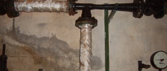
It is to solve all of the above issues that a heating elevator is used. The photo shows a sample.
How to deal with pressure changes
Features of central heating systems
It should be correctly understood that in heating mains running from boiler houses or thermal power plants to consumers, the level of pressure and temperature of the coolant differs significantly from what is supplied to apartments. Naturally, it must be reduced to safe values that meet the standards.
The intra-house coolant temperature and pressure in the heating system circuits are adjusted by adjusting the elevator unit, which is most often located in the basement of a multi-story building. In this design, hot water supplied to the heating circuit from the main is mixed with cooled return coolant.
The design of the elevator unit includes a so-called mixing chamber, equipped with a nozzle, the size of which regulates the flow of hot water into the house heating system. Since the coolant coming from the central pipeline has a very high temperature, before entering the heating circuit of the house, it is mixed with the cooled “return” water.
The mixing chamber of the elevator unit is designed approximately as shown in this diagram
The illustration above shows the main working part of the elevator assembly with a mixing chamber and nozzle. In the diagram below, the location of this element is highlighted with a yellow ellipse.
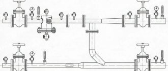
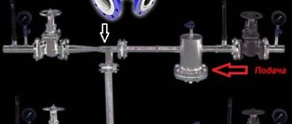
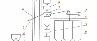
Diagram of an elevator unit that ensures that the pressure and temperature of the coolant are brought to the established standards
1 — main line for the central supply of hot coolant.
2 - return pipe of the central main.
3 - valves that disconnect the intra-house system from the central heating main.
4 - flange connections.
5 - mud filters, to prevent clogging of the pipes of the intra-house system with insoluble impurities or debris, which are difficult to completely get rid of in central lines.
6 - pressure gauges for constant monitoring of pressure in different parts of the system. Please note that pressure gauges are installed both on the main pipes, that is, before and after the elevator unit. It is the latter that controls the pressure level in the intra-house system.
7 - thermometers, also showing the temperature in different parts of the general system: tc - in the central line, at the inlet, tc - in the supply pipe of the intra-house heating system, toc and toc - in the return of the system and the central line, respectively.
8 - the main working unit, that is, the elevator itself.
9 - jumper pipe, which ensures the supply of cooled coolant from the return to the mixing chamber of the elevator unit.
10 - valves that make it possible to disconnect the intra-house wiring of the heating system from the elevator unit. This is necessary, for example, to carry out certain preventive or repair work.
11 - supply pipe for intra-house wiring, into which coolant is supplied at the required temperature and under the pressure established by the standards.
12 - return pipe for intra-house wiring.
It is clear that the diagram is given with significant simplification, simply to demonstrate the principle of operation of the elevator. In fact, this elevator unit looks much more complicated, and only heating network specialists can understand its design.
Without special knowledge, it is simply impossible to understand this “intricacy” of the pipes of the heating station of an apartment building with an elevator unit. But residents have no business meddling here - this is the lot of heating supply specialists.
Only heating system specialists should monitor the stable operation of elevator equipment. They monitor pressure and temperature indicators, conduct technical inspections, carry out preventive measures and, if devices fail, replace them with serviceable ones. Thus, most problems with insufficient or excess pressure in the intra-house system can be solved by properly adjusting the elevator unit and monitoring its operation.
The combination of simplicity of the operating principle and reliability - the elevator unit of the heating system
Despite the introduction of innovative control systems, there is no hurry to abandon the use of elevator units that are simple in their operating principle. And this is unlikely to happen in the near future. To learn more about how the elevator unit of the heating system , what devices it consists of, how it is calculated and maintained - read about all this in a special publication on our portal.
However, some nuances may depend on the apartment owners.
- For example, standard pipeline risers have a nominal diameter of 25÷33 mm. The pipes of the heating circuit of the apartment should have the same diameter. If there is a need to replace a certain section of the pipeline, then the new pipe inserted in place of the damaged section should have the same diameter as the removed one - not narrower and not wider.
- It is necessary to regularly carefully inspect the heating circuit of the apartment, especially carefully checking the connections of pipes and radiators.
- It is periodically necessary to bleed air from radiators. This is especially true for apartments located on the top floor of the building. Modern batteries go on sale already equipped with special valves, so servicing the devices is not difficult. If not, you will have to install Mayevsky taps or automatic air vents on the batteries.
The pressure reducer will protect the intra-apartment wiring from the negative consequences of pressure surges in the heating system
- To ensure that the heating circuit of the apartment does not suffer from water hammer, which, unfortunately, is not excluded during test runs of the central system before the heating season, a special device is cut into the pipe supplying coolant to the apartment at the beginning of the circuit - a pressure reducer. It prevents the negative impact of sudden pressure surges on radiators and pipe connections.
Pressure in the autonomous heating system of a private house
Most often, the heating system of a private house involves the presence of a boiler equipped with a heat exchanger. This element is probably the weakest link in terms of pressure. Most heat exchangers are designed for pressure loads exceeding 5, maximum 7 atmospheres.
Due to the fact that the maximum permissible pressure of the heating circuit is determined by the element most unstable to it, which is the heat exchanger, this value is the determining standard for autonomous heating. Therefore, when purchasing a heating unit, you need to pay special attention to what pressure it is designed for. But there is no “tragedy” in this - as a rule, for a one-story house or autonomous heating in an apartment, an indicator of 2–3 atmospheres (0.2–0.3 MPa or 20–30 meters of water column) is quite sufficient.
Scheme of an autonomous heating system with an open expansion tank.
If an open expansion tank is provided in the autonomous heating system, then there is no need to worry about the fact that pressure dangerous to the integrity of pipes and radiators may arise. The only thing that should not be forgotten is that after installing such a design, you must carefully ensure that there is a sufficient amount of coolant in the system, since it tends to evaporate.
If an open expansion tank is installed in the heating circuit, the pressure will never be higher than the static maximum. This ensures the safety of the heating system elements, but is not always effective in heating the house, precisely because the pressure is too low. The explanation is simple - the coolant, slowly moving through the channels of the circuit and overcoming hydraulic resistance, quite quickly loses its thermal potential, and approaching the “return” in the boiler room, it becomes almost cold. Therefore, the boiler has to work almost continuously, maintaining the set temperature. In this regard, fuel will be consumed uneconomically, and you will have to pay considerable sums for it.
Nowadays, there is a steady tendency to abandon such solutions in favor of systems with forced circulation and a membrane expansion tank. Moreover, specialized stores offer a very wide selection of circulation pumps with different ratings for performance and pressure generated.
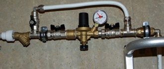
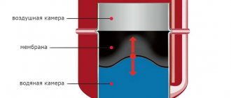
Autonomous heating safety group, which includes a pressure gauge, safety valve and automatic air vent
If a closed heating system is installed with a pump installed in it and a sealed membrane expansion tank, then in order to constantly monitor the current parameters, a pressure gauge is installed on the coolant supply pipe. In addition to this, this so-called “safety group” includes elements such as an automatic or manual air vent and a safety valve that will operate if the pressure in the system exceeds the permissible threshold.
Autonomous heating in an apartment in a multi-storey building
In recent years, more and more residents of apartments in multi-storey buildings are deciding to acquire an autonomous heating system, since, despite the high cost of equipment and problems with legalization, the return on all costs is quite high.
The main advantages of autonomous heating of an apartment is that payment for heat will have to be made only in the winter, and only based on the energy consumed. In addition, it becomes possible to turn on the heating in the off-season, when the central system is not yet functioning or is already turned off.
Basic devices that ensure the functionality and safety of an autonomous heating system
However, when installing autonomous heating in an apartment, you need to remember that monitoring its serviceability and safe operation, including adjusting pressure and temperature, falls on the homeowner. In this regard, its installation and initial start-up should not be done independently - this process must be carried out by specialists who have special permission to work with gas equipment.
The main elements and units of an autonomous heating system are most often installed in the kitchen, since all communications necessary for its arrangement, such as gas and water, are connected to it.
In most cases, a boiler for an autonomous apartment heating system is installed in the kitchen - there is probably no better place for it.
Now we need to consider the question of what could cause instability of pressure in the autonomous heating system of an apartment.
- Most often, the pressure in the system can be reduced due to a coolant leak, which can occur at pipe connections, at the radiator inlets or at the air vent. Therefore, if the pressure gauge shows a decrease in pressure in the system, it is necessary to immediately inspect the entire circuit, paying special attention to the connecting nodes. Any leak found must be repaired immediately. To do this, in some cases it is necessary to drain all the coolant from the system, and after repairs, fill it again.
An incorrectly selected or faulty membrane expansion tank may well cause unstable, high or low pressure in the heating system
- Damage to the expansion tank membrane - this can occur due to an initially incorrect calculation of this element of the heating system. The membrane may stretch, crack, or rupture completely. When choosing an expansion tank, you need to remember that its volume must correspond to the actual parameters of the heating system being created. It is clear that you want to install the most compact devices to save space, but fighting against the laws of physics is pointless.
The appendix to the article will provide a method for calculating the volume of an expansion tank for an autonomous heating system, with the attached calculator.
- Air locks in the system may occur in the first days after it is filled with new coolant. Therefore, at this time, heating usually shows slightly reduced parameters, since air must be completely released from the system. To avoid the formation of plugs, it is recommended to fill the system with low water pressure, that is, very slowly.
Many modern heating radiators are equipped with a Mayevsky tap by the manufacturer, as they say, “by default.”
To quickly get rid of air locks in the radiators, on each of them, it is necessary to install a Mayevsky tap, which is designed specifically for this purpose.
- If the pressure drops after replacing old batteries with aluminum radiators, then at first very active chemical reactions can occur inside them, during which gaseous substances are released. When this period has passed and free gases have been completely released through the air vents, the heating system will return to normal operation.
Aluminum heating radiators are “famous” for their active gas formation at the very beginning of operation. It's okay - after a short time this process should stop, and their work will return to normal.
- The pressure in the circuit may also decrease due to failure of the boiler heat exchanger (rupture or dense overgrowth with insoluble deposits - when using untreated water as a coolant. In this case, you cannot cope with the problem on your own, and you will have to call a specialist.
- The heating temperature of the coolant is set too high, when it is not too low outside. In this case, the water in the heating circuit may even boil.
- There is a blockage in one of the pipe sections or in the connecting nodes, which inhibits the normal circulation of the coolant. In this case, the pressure in the narrowed area drops, and in the area before the blockage it will be increased, as a result of which depressurization of the circuit may occur there.
- Narrowing of pipeline clearances is usually observed in old heating systems that have been in operation for decades, resulting in thick layers of scale and dirt forming on the pipe walls due to poor-quality coolant.
To talk about the balanced operation of the heating system if the circuit pipes are in this condition is simply naive!
Either cleaning, or replacing with new ones, followed by filling with high-quality coolant... A decrease in pressure due to this problem in an autonomous system occurs if the central heating system, which has been operating for a long time, has been replaced with an autonomous one, and the radiators and pipes of the circuit remain old . And in order to avoid such troubles when setting up an autonomous system, it is recommended to completely dismantle the old circuit and install a new pipeline and radiators in its place.
In addition, it is necessary to fill the closed circuit with a coolant, which can be water that has undergone the necessary preparation - mechanical filtration and softening, that is, the removal of hardness salts that cause build-ups on the walls of the pipes.
* * * * * * *
So, in order for any heating system to function well and show its efficiency, the pressure in it must be normal. If this parameter is underestimated, there is insufficient temperature in the premises of the apartment or house. As the pressure in the system increases, its most vulnerable elements may not be able to withstand it. Therefore, it is recommended to immediately bring all system parameters back to normal, and install a pressure gauge in the heating circuit in order to promptly respond to deviations from the norm, identify the causes and eliminate them. If the apartment is connected to a central heating system, the presence of control and measuring instruments will help motivate complaints to the management company about the low quality of services provided.
To understand in more detail the causes of pressure instability in autonomous heating systems, with methods for identifying them and methods for eliminating them, watch a very informative video on this topic:
Operating principle of the elevator unit
The mixing elevator serves as a device for cooling superheated water obtained from the heating network to a standard temperature before feeding it into the intra-house heating system. The principle of its reduction is to mix water at elevated temperatures from the supply pipeline and cooled water from the return pipeline.
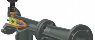
The elevator consists of several main parts. This is a suction manifold (input from the supply), a nozzle (throttle), a mixing chamber (the middle part of the elevator, where two flows are mixed and the pressure is equalized), a receiving chamber (mixture from the return), and a diffuser (exit from the elevator directly into the network with established pressure ).
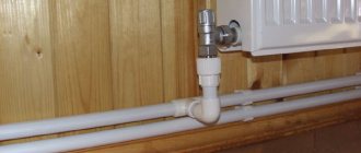
The nozzle is a narrowing device located in the steel body of the elevator device. From it, hot water at high speed and with reduced pressure enters the mixing chamber, where water from the heating network and the return pipeline are mixed by suction. In other words, hot water from the main heating network enters the elevator, in which it passes through a constriction nozzle at high speed and at reduced pressure, mixes with water from the return pipeline, and then, at a lower temperature, moves into the internal pipeline. You can see what the nozzle of a mechanical elevator directly looks like in the photo below.
In modern modifications of the elevator, the technology for controlling changes in the nozzle cross-section occurs automatically using electronics. In such a system, the mixing ratio of hot and chilled water varies, which reduces the cost of the heating system. These are so-called weather-dependent or adjustable elevators, and I wrote about this in.This structure of the elevator has an actuator to ensure its stable operation, consisting of a direction device and a throttle needle, which is driven by a toothed roller. The action of the throttle needle regulates the coolant flow.
Purpose and characteristics
The heating elevator cools the superheated water to the design temperature, after which the prepared water enters the heating devices located in residential premises. Cooling of water occurs at the moment when hot water from the supply pipeline is mixed with cooled water from the return pipeline in the elevator.
Schematic diagram of the elevator unit
The heating elevator diagram clearly shows that this unit helps to increase the efficiency of the entire heating system of the building. It is assigned two functions at once - a mixer and a circulation pump. Such a unit is inexpensive and does not require electricity. But the elevator also has several disadvantages:
- The pressure difference between the direct and reverse supply pipelines should be 0.8-2 Bar.
- The output temperature cannot be adjusted.
- There must be an accurate calculation for each elevator component.
Elevators are widely used in municipal heating systems, since they are stable in operation when the thermal and hydraulic conditions in heating networks change. The heating elevator does not require constant monitoring; all regulation consists of choosing the correct nozzle diameter.
Elevator unit in the boiler room of an apartment building
The heating elevator consists of three elements - a jet elevator, a nozzle and a vacuum chamber. There is also such a thing as elevator piping. The necessary shut-off valves, control thermometers and pressure gauges must be used here.
The selection of a heating elevator of this type is due to the fact that here the mixing coefficient varies from 2 to 5, in comparison with conventional elevators without nozzle regulation, this indicator remains unchanged. Thus, in the process of using elevators with an adjustable nozzle, heating costs can be slightly reduced.
Elevator structure
The design of this type of elevator includes a regulating actuator that ensures stable operation of the heating system at low flow rates of network water. The cone-shaped nozzle of the elevator system houses a regulating throttle needle and a guide device, which spins the water stream and plays the role of a throttle needle casing.
This mechanism has a gear shaft rotating either electrically or manually. It is designed to move the throttle needle in the longitudinal direction of the nozzle, changing its effective cross-section, after which the water flow is regulated. Thus, you can increase the consumption of network water from the calculated indicator by 10-20%, or reduce it almost until the nozzle is completely closed. Reducing the nozzle cross-section can lead to an increase in the flow rate of network water and the mixing coefficient. This way the water temperature decreases.
Actuator mechanism of the heating elevator unit
The role of the elevator unit
Heating of domestic apartment buildings is carried out through a centralized heating system. For this purpose, small thermal power plants and boiler houses are being built in small and large cities. Each of these objects produces heat for several houses or neighborhoods. The disadvantage of such a system is significant heat loss.
The principle of operation of the node
The building boundary is the outer walls and the top surface of the highest ceiling, the basement in basement buildings, or the ground level in buildings without basements. In the case of compact buildings, the boundary between individual objects is the contact plane of the top wall, and if there is a joint between two walls, the boundary between buildings passes through the center.
Building installation boundaries, depending on the type of installation, for example, fittings, inspection hatches, shut-off valves for water, gas, heating, etc. Building equipment includes all installations built into a permanent building, such as sanitary, electrical, alarm, computer, telecommunications, fire protection and general building equipment such as built-in furniture.
If the coolant path is too long, it is impossible to regulate the temperature of the transported liquid. For this reason, every home must be equipped with an elevator unit. This will solve many problems: it will significantly reduce heat consumption, and prevent accidents that may occur as a result of power failure or equipment failure.
This issue becomes especially relevant in the autumn and spring periods of the year. The coolant is heated in accordance with established standards, but its temperature depends on the outside air temperature.
Thus, the nearest houses, compared to those located further away, receive hotter coolant. It is for this reason that the elevator unit of the central heating system is so necessary. It will dilute the overheated coolant with cold water and thereby compensate for heat loss.
Why might pressure changes occur?
As mentioned earlier, in multi-story buildings, operating pressure can depend on the number of floors, as well as a number of other factors.
Pressure readings may deviate from established standards for the following reasons:
There are many reasons that can negatively affect the stability of pressure in the general house system and its compliance with established standards
- The most common prerequisite for reducing pressure in old houses is the overgrowing of the internal surfaces of pipes and radiators with lime deposits and debris.
- The pressure can drop sharply if there is no electricity in the boiler room where the circulation pumps are installed. Failure of such pumps cannot be ruled out. And in general, outdated equipment in boiler rooms that has not changed for a long time can lead to a decrease in the efficiency of the entire system.
- The cause is often a coolant leak, that is, depressurization of the system.
- The normal temperature in the room where the elevator unit is equipped, from which the coolant is “distributed” to the risers, is also important. At subzero temperatures, the unit may respond by increasing the pressure in the system.
- Sometimes the reason lies in the ill-considered actions of apartment owners. This could be the unauthorized replacement of pipes with an oversized or, conversely, narrowed diameter, the installation of taps on bypasses, the installation of additional sections of heating gates or the installation of heat exchange devices with increased thermal power, the installation of radiators in loggias or on the balcony.
- The “enemy” of the normal operation of the system is always air pockets in heating radiators if the owners do not ensure timely checking and bleeding of air.
- Poor quality coolant in a central heating system can also lead to pressure instability.
- Differences are always observed during preparatory work before the heating season, when the system is being pressure tested. Likewise, after repair or modernization work to replace radiators or pipeline sections, under test loads, when the pressure increases by 0.5÷1.5 times. These measures are carried out before the start of the heating season to identify vulnerable areas of the system in advance so that they do not appear later, during the cold season. Then this will become a real problem, since when carrying out repairs, one or even several houses have to be completely disconnected from heating.
- Water hammer is a short-term sharp increase in pressure that cannot be foreseen. Therefore, when purchasing new radiators, you need to study their characteristics, since they must have a safety margin. So, if during pressure testing of the system, the pressure rises to 10 atmospheres (bar), then you need to choose radiators designed for 13–15 atmospheres.
Pressure and temperature are monitored by common house-wide control and measuring instruments located in the heating station (at the elevator unit). If you want to independently control the condition of your section of the heating system, these devices can be installed in your apartment. They are usually placed at the coolant inlet to the radiator.
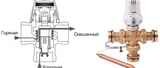
Three way valve
If it is necessary to divide the coolant flow between two consumers, a three-way heating valve is used, which can operate in two modes:
- constant mode;
- variable hydraulic mode.
A three-way valve is installed in those places in the heating circuit where it may be necessary to divide or completely shut off the flow of water. The tap material is steel, cast iron or brass. Inside the faucet there is a shut-off device, which can be ball, cylindrical or conical. The tap resembles a tee and, depending on the connection, a three-way valve on a heating system can work as a mixer. Mixing proportions can be varied within wide limits.
The ball valve is mainly used for:
- adjusting the temperature of heated floors;
- adjusting battery temperature;
- distribution of coolant in two directions.
There are two types of three-way valves - shut-off and control valves. In principle, they are almost equivalent, but with three-way shut-off valves it is more difficult to regulate the temperature smoothly.
- How to fill water into an open and closed heating system?
- Popular floor-standing gas boiler made in Russia
- How to properly bleed air from a heating radiator?
- Expansion tank for closed heating: device and principle of operation
- Gas double-circuit wall-mounted boiler Navien: error codes for malfunctions
Recommended reading
Expansion membrane tank of a heating system: device and functions Heating thermostat - operating principle of different types Bypass in a heating system - what is it and why is it needed? How to accurately choose an expansion tank for heating?
2016–2017 — Leading heating portal. All rights reserved and protected by law
Copying site materials is prohibited. Any copyright infringement will result in legal liability. Contacts
Kinds
There are two types of these devices:
- Elevators that cannot be regulated.
- Elevators, the operation of which is controlled by an electric drive.
When installing any of them, it is very important to maintain tightness. This equipment is installed in a heating system that is already functioning
Therefore, before installation, it is recommended to study the location where the subsequent placement of this equipment is planned. It is recommended to entrust this type of work to specialists who are able to understand the scheme, as well as develop drawings and perform calculations.
Methods for connecting heating devices
Nowadays, the most common are single-pipe water systems with bottom vertical wiring. In this case, the radiator is connected using hoses, because they are easy to install and well guarantee uniform heating. Such a heating system requires clear calculations of the number of sections of radiators, taking into account the level of water cooling and, in addition, carefully adjusted heating devices, since water in single-pipe systems passes through them all sequentially.
The most successful heating concept, in my opinion, is the two-pipe heating system. The principle of its operation provides for the synchronous supply of hot and draining of cold water through different pipes. In addition, this concept makes it easier to calculate individual consumption.