What is it needed for
When installing water pressure systems, there is a rule: the total diameter of all branches should not exceed the diameter of the supply pipe.
In relation to heating equipment, this rule looks like this: if the diameter of the boiler outlet fitting is 1 inch, then the system allows two circuits with a pipe diameter of ½ inch. For a small house heated only with radiators, such a system will work effectively. In fact, there are more heating circuits in a private house or cottage: heated floors. heating of several floors, utility rooms, garage. When they are connected through a tapping system, the pressure in each circuit will be insufficient to effectively heat the radiators, and the temperature in the house will not be comfortable.
Therefore, branched heating systems are made using collector systems; this technique allows you to adjust each circuit separately and set the desired temperature in each room. So, for a garage, plus 10-15ºС is enough, and for a nursery, a temperature of about plus 23-25ºС is required. In addition, heated floors should not heat up more than 35-37 degrees, otherwise it will be unpleasant to walk on them, and the floor covering may become deformed. With the help of a manifold and shut-off temperature, this problem can also be solved.
Video: using a collector system for heating a house.
Manifold groups for heating systems are sold ready-made, and they can have different configurations and the number of outlets. You can select a suitable collector assembly and install it yourself or with the help of specialists.
However, most industrial models are universal and do not always fit the needs of a particular home. Redesigning or modifying them can significantly increase costs. Therefore, in most cases it is easier to assemble it from separate blocks with your own hands, taking into account the characteristics of a particular heating system.
Manifold group for heating system assembly
The design of the universal collector group is shown in the figure. It consists of two blocks for forward and reverse coolant flow, equipped with the required number of outlets. Flow meters are installed on the supply (direct) manifold, and thermal heads are located on the return manifold to regulate the return water temperature in each circuit. With their help, you can set the required coolant flow rate, which will determine the temperature in the heating radiators.
The manifold distribution unit is equipped with a pressure gauge, circulation pump and air valves. The supply and return manifolds are combined into one unit with brackets, which also serve to attach the unit to a wall or cabinet. The price of such a block is from 15 to 20 thousand rubles. and if some of the taps are not used, its installation will be clearly impractical.
The rules for installing the finished block are shown in the video.
Comb - collector unit
The most expensive elements in a manifold distribution block are flow meters and thermal heads. To avoid overpaying for unnecessary elements, you can buy a collector unit, the so-called “comb”, and install the necessary control devices with your own hands only where necessary.
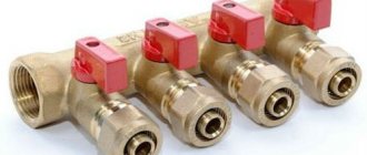
The comb consists of brass tubes with a diameter of 1 or ¾ inches with a certain number of taps with a diameter of ½ inch for heating pipes. They are also connected to each other by a bracket. The outlets on the return manifold are equipped with plugs that allow you to install thermal heads on all or part of the circuits.
Some models may be equipped with taps, with their help you can regulate the flow manually. Such combs have a cast body and are equipped with a fitting/nut thread at the ends, which allows you to quickly and easily assemble a manifold from the required number of branches.
In order to save money, the manifold for heating systems can be assembled from individual elements independently or completely made by hand.
Technical characteristics of collectors, their pros and cons
The collector is used in water radiator and underfloor heating systems, being a distribution unit for various circuits; its typical characteristics for brass or stainless steel have the following indicators:
- The standard nominal diameter of dies is 1″ or 1 1/2″ inches.
- Typical outside size of outlet fittings is 3/4″ or 1/2″ inch.
- The number of output fittings (connected circuits) is from 3 to 12.
- Connecting pipes using a Euroconus compression connector.
- Typical operating pressure in a brass system is up to 10 bar.
- The maximum temperature of the working environment is +120º C.
- The maximum length of the circuit is no more than 90 meters (depending on the diameter and material of the pipes), and their maximum deviations in length should not exceed 30%.
The industry produces two types of collectors with significant design differences - for heating radiators and heated floors, the latter always contain a mixing unit for mixing water from the return line.
Rice. 5 Wiring diagram for radiator manifold heating systems
Advantages
The distribution manifold has the following features when operating in a thermal system:
- Allows you to use a large number of independent circuits of heated floors and radiators (up to 12) in heating, each of which can always be turned off without stopping the heating and the operation of other heat exchangers.
- Ensures constant media parameters in all circuits and adjusts the supply volume (pressure and temperature) in each of them - this increases the comfort of heating use.
- A significant advantage of the manifold comb is the ability to install electric servos in it, which block the flow with valves depending on the readings of the sensor connected to them; they can be installed anywhere - in a room, on a radiator or near the surface of a heated floor. Thus, automatic regulation of the temperature of the heating circuits is achieved and energy resources are saved.
- The system uses flexible small-diameter heating pipes made of relatively inexpensive polymer materials, having a small cross-section and secretly passing under the floors; the coolant is supplied to the upper or lower floors without risers. This design increases the aesthetic appearance of housing and minimizes financial costs.
- It is quite easy to increase the length of the collector by attaching additional links with output fittings to connect new circuits.
- The reliability of the scheme is quite high due to the minimum number of hidden connections, and when installing heated floors they are completely absent - a pipe of any length is connected to the inlet and outlet of the collector at points of direct visibility and convenient access. The same can be said about radiators, which are connected through easily accessible fittings from below, not far from the floor surface.
- High maintainability is ensured by the ability to disconnect any branch for repair or replacement of devices without disrupting the operation of other circuits.
Rice. 6 Installation of supply and return pipelines in a collector system - example
Flaws
The disadvantages of collectors include their following parameters:
- The cost of a factory-made collector assembly from trusted manufacturers made of corrosion-resistant metals is quite high and can reach 300 USD, which is a fairly significant amount for the average consumer. Costs can be reduced by using lower quality and reliable plastic models, the price of which reaches 50 USD.
- For efficient heating, the length of all circuits is kept as minimal as possible; for this purpose, radial wiring is used and they try to place the collector as close to the center of the house as possible in order to achieve the same length of all circuits as possible. In practice, placing the collector in the center of the house is not always possible for technical reasons; moreover, such an installation spoils the aesthetics of the appearance of the room with the installed distribution system.
- Assembling the distribution collector system of a private house with your own hands by an unprepared homeowner is quite problematic; installation and configuration work can only be carried out by highly qualified specialists with extensive experience. Paying for the services of professionals will require significant financial resources, which is difficult for the average person.
- As noted above, the pipes of all circuits pass under the floor, that is, you will have to screed not only in rooms with heated floors, but also on all floors in the house to level the floor level and hide the pipes that fit the circuits. Carrying out these works will also require significant financial expenses not only for wages of workers, but also for materials (thermal insulation, mesh, screed mortar).
- The collector circuit is not gravity-fed, that is, in the absence of electricity, the operation of the circulation electric pump in the collector unit stops, and the movement of the coolant flow stops along with the heating of the premises.
Features of installation of the collector system
Installation of heating systems is carried out before finishing work on laying floor and wall coverings; the pipeline running along the floor is tied to a strong metal mesh and filled with a screed located on the insulation layer.
Apartment house
The implementation of collector heating in a residential apartment building is practically not used in everyday life, this is primarily due to the presence of radiator heating in buildings, in which all rooms in the apartment are heated by radiators. Laying circuits for heating rooms through floors is associated with significant financial costs and is ineffective; moreover, a comb is not required for laying a small number and short length of loops. A significant factor that makes the installation of collector heating in an apartment building useless is the imbalance and violation of the temperature regime of the entire house system, as a result of which penalties and dismantling of the installed heated floor are possible.
Cottage
Collector combs are the main elements in organizing heating of country houses and cottages; they are usually placed in the wall of rooms located in the center of the house on each floor, connected to a riser built into them.
To do this, during the construction stage, a recess is placed in the wall in which the comb is placed; to improve the aesthetic appearance, a manifold cabinet with closing doors is placed in the place of insertion.
One circuit is used for each room; if there are several radiators in the room, they are connected in series using a single-pipe passing or pass-through circuit (Leningrad). Several small circuits are installed if the area of the premises is large and the maximum length of the pipeline does not ensure its coverage at a given pitch.
Rice. 14 Combined heating system
Common house collector group
The main comb performs the same functions as the TP collector - it distributes the coolant among the branches of the heating network of various loads and lengths. The element is made of steel - stainless or black, the profile of the main chamber is round or square.
There are compact models of distributors for 3–5 circuits, made in the form of one pipe. Here's the trick: the return manifold is placed inside the feed chamber. As a result, we get 1 common housing with 2 cameras of equal capacity.
In the vast majority of country houses with an area of up to 300 m², distribution manifolds are not needed. For several heat consumers, it is used, described in a separate article. When should you think about buying a communal heating comb:
- the number of floors of the cottage is at least two, the total area is over 300 square meters;
- for heating, at least 2 heat sources are used - gas, solid fuel, electric, and so on;
- the number of individual radiator heating branches is 3 or more;
- The boiler room diagram contains an indirect heating boiler, heating circuits for auxiliary buildings, and heating of the pool.
The listed factors must be considered separately and together, and to select a model of specific sizes, the load on each branch must be calculated. Hence the conclusion: it is better not to buy a collector without consulting an expert.
Drawing of a coplanar manifold and photo of the finished product with pumping groups
Advantages and disadvantages of radiant heating systems
Positive sides
The main advantage of the beam scheme is ease of use.
Special equipment makes control of the climate network as ergonomic and convenient as possible:
- You can set the temperature of each heating radiator in the house without leaving the manifold cabinet. In addition, if necessary, you can completely shut off the water supply to any element of the system without disrupting the functionality of the entire heating network.
- Each pair of pipes connects the collector to only one radiator. Therefore, you can use small-diameter pipelines that can be easily disguised under the floor covering. Among other things, this allows you to partially warm the floor surface.
Radiant heating system pipes are laid before the floor is poured
- Thanks to the use of special devices (the so-called hydraulic arrows - collectors with a large diameter), it is possible to create several heating zones in the house with different coolant temperatures.
In this case, a short circuit is organized between the supply and return pipes. Heated water constantly circulates in the hydraulic arrow, and it can be taken at different distances (the temperature will depend on this).
Negative sides
To complete the picture, we should also talk about the disadvantages of using a radial heating system.
It is because of them that, despite all the advantages, it is not very widespread:
- Greatly increased flow of supply and discharge pipes. The more spacious the house and the more complex the geometry of the rooms, the more parts will be needed. In addition, the complexity of installation increases, which cannot but affect the estimated cost of construction.
A radiant heating system requires the use of a huge number of pipes and collectors
- The need for hidden installation. While a traditional tee system can be installed along walls, you won’t be able to place a huge number of pipes this way. They must be hidden under the floor. You can also wall it up in walls, but in this case the consumption of material will increase even more.
- No joints. When designing pipelines, it is imperative to ensure that the pipe under the floor does not contain a single joint. Breaks most often occur in this place, and the cost of repairing the breakdown will be far from low and very labor-intensive.
- If the system design includes several circuits with different coolant temperatures, then each of them must be equipped with a circulation pump.
Flaws
There are several main disadvantages that must be taken into account before installing such a system in your home:
- Much more pipe is used to connect all the components than a series connection. The larger the area of the house, the more complex the wiring plan. This increases the difference in costs.
- Ordinary one- or two-pipe heating is usually mounted on walls. In this case, such mounting will not be aesthetically pleasing.
- The location of the connections in the screed has one important factor - there should be no seams or joints. After all, this is a potential leak point. And opening up a concrete floor is an unpleasant idea.
- The total resistance of the water circuit is high, especially when heating a two-story house. Especially when installing narrow pipes. You can immediately forget about natural circulation, because a small difference is definitely not enough. The solution is obvious - a powerful pump.
- The use of several circuits at once usually forces the installation of the same number of pressure systems. All this increases the consumables not only at the time of installation, but also during use.
- Connecting forced circulation automatically makes the system dependent on electricity. Any problems with this type of energy can lead to heating failure when the boiler is completely working.
Self-assembly of a heating manifold
Heating collectors are usually supplied assembled by the manufacturer; a standard-length circulation pump is installed later on an American-type threaded connection. Sometimes components are supplied to consumers separately; the assembly procedure consists of the following operations:
- Flow meters are installed on the supply comb and the end air vent is screwed into the right end.
- A valve is connected to the return comb with previously installed caps on the shut-off valves through the American connection on the right side.
- On both combs on the left, through the American connection, connectors are installed to connect the compression electric pump, and they are positioned so that the fitting for installing the thermometer is on the front side.
- A tee is screwed into the return comb, to which the thermostatic head is connected.
- Using a threaded connection (American) for mounting electric circulation pumps and gaskets from the kit, the pump is connected to the upper and lower combs.
- Upon completion of the work, pipes of standard diameter are connected to the collector block using the Eurocones included in the kit.
All main connections are sealed using rubber gaskets supplied with the unit and the electric pump; sometimes seals are missing in the tap and tee of the supply comb, then linen tow or other plumbing materials are used for sealing
To carry out the work, one adjustable wrench is enough, but it is important not to overtighten the nuts - this can lead to rupture of the gaskets
Rice. 18 PEX and PE-RT pipes
The nuances of homemade work
The main condition for correct heating operation is the creation of hydraulic balance in the system. The ring collector for heating must have the same throughput capacity of the incoming pipe (the cross-section of the main pipe connected to the supply line) as the sum of the same indicators in all circuits. For example, for a system with 4 circuits, it looks like this:
D = D1 + D2 +D3 +D4
When making a heating manifold with your own hands, remember that the distance between the supply and return sections of the pipe should be a value equal to at least six comb diameters.
When installing the device, take into account the following nuances:
- an electric boiler or gas boiler is connected to the upper or lower pipes
- the circulation pump only fits into the end side of the comb
- heating circuits are connected to the top or bottom of the collector.
To heat a house with a large area, circulation pumps are installed on each circuit. In addition, to select the optimal volume of coolant, additional equipment is installed on each inlet and outlet pipe - balancing flow meters and adjustment valves. These devices limit the flow of hot liquid to a single pipe.
In order for the boiler distribution manifold to perform its functions in full, it is necessary that the length of all circuits connected to it be approximately the same length.
It is possible (but not necessary) to additionally equip a mixing unit when manufacturing heating collectors. It consists of pipes that connect the inlet and return combs. In this case, to regulate the amount of cold and hot water as a percentage, install a two or three-way valve. It is controlled by a closed-type servo drive, which receives a signal from a temperature sensor installed in the heating circuit.
This entire design allows you to regulate the heating temperature of a particular room or a separate circuit. If too hot water enters the collector in the boiler room, the flow of cold liquid into the system increases.
For a complex heating system in which several collectors are installed, a hydraulic arrow is installed. It improves the performance of distribution combs.
A manifold for a boiler room, which you make yourself, will ensure normal heating operation only if you accurately select the parameters of the system piping. Therefore, you first need to entrust the calculations to a professional, and then get to work.
Remember that a comfortable temperature in your home depends on many factors. Only a fully balanced system will ensure correct heating operation.
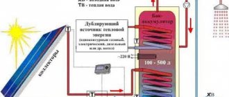
Making a solar collector for alternative heating in your home
Recently, the interest of ordinary people in renewable energy sources has increased. Because of this, many homeowners are looking to buy a solar collector for home heating, which converts the sun's energy to heat water. But the decision to buy a solar collector for heating in a store is not always rational. The cost of the finished device is far from budget, so such a purchase can hit the family budget hard.
To avoid expenses, you can make a solar vacuum collector for heating yourself. Various solar collectors for home heating, reviews of which are positive, have the following design details:
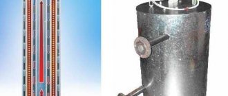
- container for storing heated water;
- heat exchanger;
- device for collecting solar energy;
- insulating layer.
The materials from which the collector can be made are very diverse. There are known technologies for the independent production of solar collectors from polypropylene, ordinary garden hoses, window frames, plastic bottles, old refrigeration units and other available materials. The collector assembly diagram directly depends on the type of material chosen, so it is worth studying after the owner has decided on the concept of the collector.
Self-made vacuum solar collectors for home heating, the price of which in the store is $200 or more, can be used as full-fledged heating sources.
Vacuum solar collectors have a number of advantages:
- energy efficiency;
- environmental friendliness;
- autonomy;
- availability.
It is not difficult to make traditional distribution or solar collectors for heating your home with your own hands. This does not require large material costs, complex technological equipment or solid experience. However, these hand-made devices will greatly optimize the home heating system and will help the owner create a reliable, efficient and uniform source of heating for his home.
- How to fill water into an open and closed heating system?
- Popular floor-standing gas boiler made in Russia
- How to properly bleed air from a heating radiator?
- Expansion tank for closed heating: device and principle of operation
- Gas double-circuit wall-mounted boiler Navien: error codes for malfunctions
Recommended reading
Heating thermostat - operating principle of different types How to make an expansion tank for heating with your own hands? Bypass in a heating system - what is it and why is it necessary? Expansion tank for closed heating: device and principle of operation
2016–2017 — Leading heating portal. All rights reserved and protected by law
Copying site materials is prohibited. Any copyright infringement will result in legal liability. Contacts
Definitions
A collector (comb) is a type of plumbing fixture that distributes coolant along the contours of consumers. Simply put, this is a piece of thick pipe that has one inlet and several outlets. Its appearance was facilitated by the complication of heating systems, the spread of flooring and radiant radiator wiring, and the increase in the number of heat consumption points in the house.
Heating manifold. Click on photo to enlarge.
The coolant flows through the main line from the boiler room to the floor collectors. They have a number of inputs/outputs that corresponds to the number of thermal energy consumers (radiators, convectors, etc.) on the floor. Unlike a series connection (using tees), the collector heating system is distinguished by independent supply to each heating device. This scheme makes it possible to control the temperature regime of each radiator, if necessary, allowing it to be turned off without damage to other heating devices. To do this, each collector outlet is equipped with its own shut-off valves.
Mixed wiring is possible, when several small circuits with independent control are connected to the collector. In this case, a sequential system for connecting heating devices is used within each circuit. With a collector, the heating circuit becomes simpler, allowing you to eliminate the need for seals and additional shut-off and control valves. Using collectors and collector units, you can significantly reduce costs when designing, installing and commissioning a heating system.
Select a manifold for your apartment's water supply by size
Any collector is selected according to the required number of branches. Next, let's look at its dimensions. The smaller the axial distance between the taps, the more compact the collector.
Please note that the taps of some collectors are made at an angle to the taps. This simplifies their maintenance in row installations in cramped conditions.
If there are a large number of branches, do not look for “long” collectors. Take two, for example 3+2 or 4+2 and combine them. This is provided by technology.
Is it possible to make a heating collector with your own hands?
Sometimes it happens that the autonomous heating in your own home does not work very efficiently. It seems that the boiler power was selected correctly, the piping was done correctly, and all installation work was carried out at a professional level, but the temperature in the house is not what you would like. What to do in this case? There is only one way out - install a distribution manifold. By the way, there is no need to buy it ready-made, the design of the collector is not very complicated, so making it yourself is not the biggest problem. So, in this article we will answer one question: how to make a distribution manifold with your own hands?
Conclusions and useful video on the topic
Detailed technical process for assembling the collector group:
Ready-made combs for arranging heated floors, which are not always equipped with the necessary functionality, are, due to their high cost, not available to the general public. Let's see how to assemble a budget version of the design with your own hands:
The distribution group can also be implemented using polypropylene pipes. You can learn how to do this from the video:
Correct selection of components and installation of the collector unit is the key to efficient and reliable operation of the heating main. Due to the minimum number of connections, the risk of leaks is minimized. An important advantage is the ability to control and configure each heating circuit.
Share with readers your experience in assembling and connecting the distribution manifold.
Please leave comments on the article, ask questions and participate in discussions. The feedback form is located below. Date: September 25, 2022
Types of collectors
From two to twelve circuits can be connected to the collector, and during system operation the number of circuits involved may vary.
At the moment, the distribution manifold for heating can be made of the following materials:
- polymers;
- copper;
- brass;
- steel.
For ease of operation, basic types of collectors can be equipped with additional options, including:
- thermostat;
- circuit pressure monitoring detector;
- automation for protection against emergency situations;
- air release valves;
- programmable mixers;
- electronic valves.
How to design a manifold
Designing a heating manifold is not that difficult. The device is simple, and you don’t need any special knowledge of plumbing to create a sketch and subsequent drawing. Let's break down what you need to consider when creating:
what material do you plan to use;
System diagram with collector
Remember! Metal is considered the best option for a heating manifold, because this material is highly resistant to high temperatures, durable and reliable in operation, quite easy to install, and also easy to maintain.
how many taps do you need - how many coolant consumers should the heating manifold provide?
Having calculated all this, you can begin to create a sketch of the future product.
- Take a sheet of paper and draw two rectangles parallel to each other - this will be the basis for the heating manifold.
- Draw the connection for the boiler and boiler at the ends of the base.
- Draw the number of pipes that will go to the hot and cold tanks.
- Then remove the required number of pipes from the hot reservoir for all elements that require coolant.
This brings the creation of the project to an end, now transfer the drawing under the heating collector of a private house onto a blank sheet of paper and mark the diameter of your pipes there. After this, you can begin to select materials to install a heating collector with your own hands in your own home.
Fixation process
If you use the two-tap method when connecting the pump to the boiler, then one of the shut-off elements is installed immediately after the distribution manifold. Next, screw on the filter. For reliability, you should use certain linings and lubricants that will increase the tightness of the system. Next, proceed to install the circulation pump. It must be of a certain type and it must be fixed in a position in which there will be better access to the working elements. After this, install a check valve and a second tap. As a result, the system is completely installed. If you decide to save money and eliminate the second tap, then you will need to choose a high-quality check valve.
Thus, pumps are connected to the boiler at each flange of the distribution manifold. In this case, you must strictly adhere to this proposal, since the project must not be violated under any circumstances. There is a considerable amount of advice on the Internet that helps to some extent, but some simply do not make sense to use. Thus, it is worth entrusting this work to professionals. Connecting any equipment to the heating system must be done in the summer. This way you can eliminate delays in service and so on.
Pipe selection
The collector heating system must be equipped with pipes selected in accordance with certain requirements:
- It is best if the pipe is in a coil, since the optimal choice for collector wiring is the absence of connections.
- The material must be resistant to corrosion and the pipes must last for many years. The reason for this requirement is the same as in the first point: the possibility of premature intervention in a monolithic screed should be minimized.
- The material must be flexible enough, since pipes are not always laid in a perfectly straight line.
- Thermal resistance and tensile strength characteristics are dictated by the environment in which the heating system operates. For a private home, the recommended indicators are approximately the following: pressure - up to 1.5 atmospheres, temperature - up to 75 degrees for radiators and up to 40 degrees for a heated floor system. If we are talking about an apartment building, the maximum possible indicators should be higher: pressure - up to 15 atmospheres, temperature - up to 110-120 degrees above zero.
Multi-storey building
In this case, the best choice is a corrugated stainless steel pipe. The technical capabilities of this material make it possible to successfully cope with loads: coolant temperatures up to 110 degrees above zero, pressure levels up to 15 atmospheres, destruction pressure up to 210 kilograms per square centimeter.
Stainless steel pipe has good flexibility, since the bending radius can reach the diameter of the product. Installation work is carried out according to a simple algorithm: the pipe is directed into the fitting and secured with a nut.
A private house
Using stainless steel is expensive. Since a self-contained heating system has predictable performance characteristics, you can take a more affordable route by using cross-linked polyethylene. Polyethylene pipes are sold in coils of 200 meters. The material can withstand temperatures up to 95 degrees, and in the short term up to 110 degrees above zero. The permissible level of pressure for destruction is 10 kilograms per square centimeter.
Polyethylene pipe fittings are made of plastic or brass. Each fitting is equipped with a locking ring, which is threaded onto the pipe. The peculiarity of cross-linked polyethylene is its memory for mechanical stress: if the material is stretched using an extender and a fitting is installed in the gap, after a short time the pipe will tightly clamp this part. The connection is secured with a locking ring.
The most popular models
1. Oventrop Multidis SF.
An inch heating comb is designed to organize heating with a water heated floor. Made from tool steel, characterized by high wear resistance. Main characteristics:
- permissible pressure in the circuit – 6 bar;
- coolant temperature – +70 °C.
The series is produced with valve inserts M30x1.5, and can also be equipped with a flow meter for connecting circuits located in different rooms. A bonus from the manufacturer - soundproofed mounting clamps. The number of simultaneously serviced branches is from 2 to 12. The price, accordingly, is 5650-18800 rubles.
To work with high-temperature appliances, Oventrop suggests using a heating system distribution manifold made of Multidis SH stainless steel with a Mayevsky tap. The design can already withstand 10 bar at +95-100 °C, the comb throughput is 1-4 l/min. However, products with 2 circuits have slightly weaker performance. The cost of Oventrop SH hydraulic valves ranges from 2780-9980 rubles.
Plumbers: You'll pay up to 50% LESS on your water bills with this faucet attachment
- HKV – brass underfloor heating manifold. Maintains a pressure of 6 bar in the range of +80-95 °C. Rehau version D is additionally equipped with a rotameter and a tap for filling the system.
- HLV is a heating distribution comb designed for radiators, although its characteristics are identical to the description of HKV. The only difference is in the configuration: a Eurocone is already provided here and the possibility of a threaded clamp connection with pipes.
The manufacturer Rehau also offers to buy separate Rautitan combs with three outlets for pipeline installation using sliding sleeves.
Heating distribution manifold made of steel with anti-corrosion coating. It operates in systems with temperatures up to +110 °C at a pressure of 6 bar and is hidden in a special heat-insulating casing. The throughput of the comb channels is 3 m3/h. Here the choice of designs is not very rich: it is possible to connect only from 3 to 7 circuits. The cost of such hydraulic valves will range from 15,340 to 252,650 rubles.
Stainless steel manifolds are produced in an even more modest range - for 2 or 3 circuits. With the same characteristics, they can be purchased for 19,670-24,940 rubles. The most functional Meibes line is the RW series, which already comes complete with various connecting elements, thermostats and manual valves.
- F – a flow meter is built into the supply;
- BV – has quarter taps;
- C – provides for extension of the comb through a nipple connection.
Each Danfoss heating manifold allows a system pressure of 10 atm at an optimal temperature (+90 °C). The design of the brackets is interesting - they fix paired combs with a slight offset relative to each other for more convenient maintenance. Moreover, all valves are equipped with plastic heads with marked markings, which allows you to set their position manually without the use of tools. The price of Danfoss models, depending on the number of connected circuits and additional options, varies between 5170 - 31,390.
The heating manifold can be selected for a Eurocone with 1/2″ or 3/4″ outlets or with a metric threaded connection. Far combs can withstand pressure up to 10 atm at temperatures not exceeding +100 °C. But the number of outlet pipes is small: from 2 to 4, but the price is the lowest of all the products reviewed in our review (730-1700 rubles for an unpaired distributor).
Tips for choosing
Despite the apparent simplicity of the combs, they need to be selected based on several technical parameters:
1. Pressure in the system - this value determines what material the distribution manifold can be made from.
2. The throughput must be sufficient so that the connected heating circuits do not “starve” from a lack of coolant.
3. Energy consumption of the mixing unit - as a rule, it is determined by the total power of the circulation pumps.
4
Possibility of adding circuits - this parameter should be paid attention only when in the future it is planned to build additional objects that require heating
The number of pipes on the hydraulic distributor must correspond to the number of connected branches (heating devices). In some cases, it is better to install several collectors, for example, in a two-story house - one block on each level. It is also possible to install unpaired combs at different points: one on the supply, the other on the return.
Finally, experts and experienced installers in their reviews advise not to skimp on buying a good collector. In order for it to serve for a long time and not cause any problems, the name on the box must be known.
What is a heating manifold
A heating manifold is a device whose task is to properly distribute the coolant throughout the heating system of a private home. The collector helps to rationalize home heating, allowing you to spend less on fuel consumption, and therefore save money. He is:
- two pipes for hot and waste coolant;
- pipes through which the liquid will be distributed to all elements of the heating system;
- pipes designed to return cooled coolant back to the boiler;
- pumps;
- regulators.
Such a device is usually made of metal pipes, but the price of such products will be quite high, because if your room is large, then you will need a lot of material.
Manifold for heating system
Tip: If your budget does not allow you to connect every element to the heating manifold, there is an option to use polypropylene pipes.
The advantages of such a device are:
- uniform distribution of coolant in the pipeline;
- complete heating of the entire room, and not just certain places;
- increasing the efficiency of the hydraulic heating system;
- reduction of fuel consumption;
- the ability to install additional pipe bends on the collector if you want to add elements to the wiring.
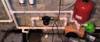
It is best to install the collector on the heating system in a special cabinet that will protect and hide the system from dust or other influences. It is advisable that such a unit be installed in a boiler room or a separate room, but nothing bad will happen if you simply mount the collector on the wall near the heating boiler.
Is it possible to install the collector below the level of the heated floor - for example, in the basement?
There are cases when the distribution and mixing unit has to be installed not on the floor where the heated floor is laid, but below, for example, if the boiler room is in the basement, or you simply do not want to spoil the interior of the apartment.
This wiring is acceptable; the collector is installed in the same sequence as usual. There is only one problem - automatic bleeding of air masses from the line is not possible if the air vent is located on the comb.
The solution is to install an air vent on the return pipe between the comb and the floor hinges, and a shut-off device with a shut-off valve is installed in front of it. It is necessary to have access to an air vent.
For your information! Since an air vent is required for each branch of the floor, it is worth considering the advisability of installing the collector below the level of the heated floor.
A warm water floor is a modern heating system that is perfect for installing in private homes. With proper installation of the floor “pie” and the collector, the design can provide comfortable conditions in the room.
Manifolds for radiators and heated floors
The difference between a floor collector and a radiator collector is in the design associated with the difference in operating temperatures and the lower hydraulic resistance of the radiator elements. The design of the block for connecting underfloor heating is much more complex; it includes a large number of control water fittings and a circulation pump for multi-circuit systems.
The standard manifold block for household radiators has a simple design: it consists of supply and return manifolds of large cross-section, from which come fittings for connecting pipes going to the radiators. The device usually does not have any adjusting, tuning valves or other complex devices, so connecting and installing it does not cause difficulties for most homeowners. Heating radiators are connected to the unit through pipes running in the floor and connected from below at one point; to place a straight pipeline it is not necessary to make a screed; it can be laid in a groove cut or knocked out in the slab.
A typical collector block is a technically complex element with a large number of adjustments and settings; often a circular electric pump is installed in the system. When installing the block, you should distinguish between the forward and reverse feed combs; for convenience, they are marked with red and blue paints, respectively. Also, adjustable flow meters with a transparent cap and marked divisions indicating the volume of liquid passing through them are most often placed in a straight line; it is marked with an internal red indicator head.
Typically, the maximum value of the transmitted flow does not exceed 5 cubic meters per hour (corresponding to division 5 on the cap), the minimum mark is 0.5. If the indicator heads are in the upper part, then when the water flow passes through the supply comb, the indicator lowers and shows the volume of liquid passing through. Sometimes the heads are located at the bottom, in this case the flow moves in the opposite direction from the heating circuit to the comb and, accordingly, the flow meters are installed in the return flow bar.
The standard block provides space for the location of the thermostat sensor, there are exhaust valves for bleeding air in the supply and return combs, valves are installed in place of which there are seats for servos that perform automatic control of operating modes.
Rice. 11 Hydroarrow - installation and connection diagram
Basic models of collector blocks
For closed circulation systems, three models of collectors are known, each of which differs in a number of characteristics:
- A collector connected to the radiator.
- The second known system is a hydraulic arrow.
- Solar collector structures.
Each of the known models of the collector block has a number of operating features, installation requirements, advantages and disadvantages.
Why do you need a distribution manifold for a heating system?
A complex and extensive heating system with a liquid coolant implies the correct organization of flow movement along numerous circuits. Only in this case will heating the house be effective and controllable. But do not install a separate boiler in each room - it is much easier to use collectors in the circuit, which will distribute the heated flow with the required indicators to the heating devices. They will not only be able to control the temperature of the circulating fluid, but will also ensure its uniform supply to all connected branches.
The distribution manifold externally resembles a hollow volumetric comb, into the base of which the general coolant flow enters, and then is divided into separate hoses in the side pipes and sent through all existing channels. Exactly the same unit collects back all the waste liquid and supplies it to the boiler, closing the cycle. Thanks to this scheme, one water heater can be connected to heating devices with different characteristics: to a hot water storage tank, heated floors, classic radiators.
Each manifold pipe is equipped with valves with thermostatic heads. Depending on the specified heating parameters, they dose hot and cold water in those systems where pre-mixing is required. For example, heated floors only work at +40-50 °C, while wall-mounted radiators require a temperature of at least +80 °C. The heating manifold should pass the hot flow to the radiators without changes, and dilute it with cold water in the sections for floor threads. To do this, the supply valve in its section partially blocks the “red” pipe, reducing its cross-section.
A clever meter that saves electricity Pays for itself in 2 months!
The use of a comb simplifies the design of a branched system, eliminating the need for additional pumps and thermostatic valves. Everything that is necessary for normal heating operation is collected in one place - this makes it easier to configure and maintain a complex circuit. In addition, almost any distribution manifold has a built-in end air vent, which allows you to remove bubbles from the pipes that reduce heating efficiency.
Modifications of distributor combs
Today, there are many types of collectors for heating systems on the equipment market.
Manufacturers offer both connecting links of the simplest design, the design of which does not provide for the presence of auxiliary fittings for regulating the equipment, and manifold blocks with a full set of built-in elements.
A collector block that includes all the necessary functional elements to create conditions for uninterrupted and high-performance operation of the heating system
The simple-to-use devices are brass models with one-inch branches, equipped with two connecting holes on the sides.
On the return collector, such devices have plugs, instead of which, in the case of “expanding” the system, additional devices can always be installed.
Intermediate assemblies that are more complex in design are equipped with ball valves. For each outlet they provide for the installation of shut-off control valves. Sophisticated, expensive models can be equipped with:
- flow meters , the main purpose of which is to regulate the flow of coolant in each loop;
- temperature sensors designed to monitor the temperature of each heating device;
- automatic air release valves
- electronic valves and mixers aimed at maintaining the programmed temperature.
The number of circuits, depending on the connected consumers, can vary from 2 to 10 pieces.
Regardless of the complexity and versatility of the equipment, materials that are resistant to external factors are used in the manufacture of manifold block combs
If we take the manufacturing material as a basis, then intermediate prefabricated collectors are:
- Brass - characterized by high performance parameters at an affordable price.
- Stainless steel structures are extremely durable. They can withstand high pressure with ease.
- Polypropylene - models made of polymer materials, although they have a low price, are inferior in all characteristics to their metal “brothers”.
Models made of metal are treated with anti-corrosion compounds and covered with thermal insulation to extend their service life and improve performance parameters.
Separating structures made of polymers are used in the construction of systems heated by boilers with a power of 13 to 35 kW
Parts of the device can be cast or equipped with collet clamps, allowing connection to metal-plastic pipes.
But experts do not advise choosing combs with collet clamps, since they often “sin” by leaking coolant at the valve connection points. This occurs due to rapid failure of the seal. And it is not always possible to replace it.
Collectors are used in single- and two-pipe heating schemes. In single-pipe systems, one comb supplies the heated coolant and receives the cooled one
Collector-beam heating system
Collector in a radiant heating system.
The heating collector should be considered together with a consideration of the radial circuit for distributing the coolant, this will make it easier to understand its main functions and advantages.
As you know, there are three main types of pipe routing.
- Single-pipe scheme. Here the radiators are connected in series, that is, the coolant is supplied to the first device, then passes through the battery and goes to the next, gradually passing through the entire circuit and returning to the boiler. It is obvious that after each radiator the water cools down and the batteries are heated unevenly;
- Two-pipe scheme. This solution provides for water supply through one pipe, and drainage through the second, that is, the circuit consists of two lines, between which radiators are connected in parallel. This scheme allows the devices to be heated more evenly;
- Beam scheme. The coolant is supplied to the distribution unit (heating system manifold), from where it is supplied to each radiator through a separate pipe, and then returned through return pipes, collected by a comb and supplied to the boiler. This way you can achieve the most even distribution of heat in the room.
One-pipe and two-pipe wiring diagrams.
Beam wiring diagram.
Important! As you can see, there are many circuits in the beam circuit, one for each battery. Therefore, for normal operation of the system, a circulation pump is needed that can provide the necessary parameters of pressure and circulation rate of the coolant
The radial circuit allows each individual radiator to be heated as evenly as possible; moreover, it makes it possible to regulate the intensity of heat supply to each battery.
Manifold cabinet for radiator heating with supply and return combs.
Also, in such a scheme, you can turn off any device without changing the operation of the entire system, and in multi-storey buildings you can turn off entire floors without interrupting the supply of coolant to the remaining sections of the building.
To realize these advantages, heating collectors are used, which are included in the distribution unit in the form of a pair of devices - supply and return combs. Tying the heating manifold with shut-off valves, air and drain valves, flow meters and thermostatic heads allows automatic regulation of temperature conditions on each individual heating device.
The use of flow meters makes it possible to regulate the flow.
Important! Most often, such wiring is used in the construction of heating systems for private houses and cottages, but this scheme can also be used in an apartment with a centralized coolant supply. It should be remembered that it is best to install pipes under the floor
Another advantage of radial wiring is the ability to hide the pipeline under the baseboard or in the thickness of the floor. Often it is this feature that influences the choice of wiring diagram.
In a “warm floor” system, a manifold for floor heating systems is necessarily used.
It is also impossible not to mention such a system as “warm floor”. Here the circuits are not connected to radiators, but are laid in a special way in the floor screed in order to warm it up.
The only significant drawback of this solution is the high price of materials and labor.
Installation of heating with forced circulation in a one-story house
Do-it-yourself heating of a one-story house is done using a technology that includes the following operations:
- First of all, the heating boiler is installed;
- The boiler is connected to a chimney that is led outside the building;
- When using a gas boiler, you must connect to the main line (this operation must be performed by specialists from the gas service);
- Heating batteries are installed along the walls in pre-selected places;
- All structural elements are connected by pipelines;
- The circulation pump and expansion tank cut into the return pipe;
- The pipelines are connected to the corresponding boiler nozzles;
- The assembled system must be launched in test mode, after which it can be put into operation.
This technology is common to all types of heating systems - there are minor differences only in the laying of pipes and installation of radiators.
Pipe selection
Although pipelines made of various materials can be used to supply water and install circuits, in everyday life they mainly use polymers, which are supplied in coils of various lengths and are easily bent when laying loops.
The main materials of heating pipelines are: metal-plastic made of cross-linked polyethylene PEX with an aluminum layer between the inner and outer shells, cross-linked PEX and heat-resistant PE-RT polyethylene.
It should be noted that metal plastic is not very practical as a material for heated floors - due to its high rigidity, it is difficult to bend with a small radius, and mechanical stress on the surface during installation or before laying the screed leads to bends and breaks. You can repair a metal-plastic pipeline by inserting a section connected using compression or crimp fittings - this leads to a decrease in the passage channel and an increase in hydraulic resistance.
Pipes made of cross-linked and heat-resistant polyethylene have the same service life of about 50 years; it is believed that the PE-RT pipeline is easier to install in rooms with low temperatures, and if damaged, it can be easily repaired by soldering, although the technology is not very well known. Also, the cost of PE-RT is lower than cross-linked polyethylene PEX, although there are enough products of both categories at a relatively low price on the construction market.
Rice. 19 Basic pipe laying schemes for heated floors
Feed and return manifold comb device
Combs are one of the main elements of the collector circuit; their main function is to distribute the coolant flow along the heating circuits. The element has a different design for lines of connected radiators and heated floors, the maximum number of involved circuits per collector does not exceed 12.
In relation to the diameters of the outlet fittings, the comb has a large cross-section (1.1 1/2 inches versus 3/4) and is connected to the main line through an end connection with elements of plumbing fittings. Typically, the pipeline is connected to the outlet fittings using compression fittings (Eurocones) - this method can be used to connect pipes made of cross-linked and heat-resistant polyethylene, metal-plastic, most often used in manifold heating systems. Combs are made of stainless steel, brass, plastic, some modifications are assembled from individual links.
Ready-made designs of heating collectors
The construction market offers products from various manufacturers of collector heating equipment, including such popular brands as ProfLine, Valtec, Luxor, Rehay, Shout.
The most commonly used materials in the manufacture of manifolds are stainless steel and chrome-plated brass; much less often in domestic heating, equipment is selected from low-cost polymers (polypropylene), which do not provide for the installation of flow meters and valves for servo drives.
Rice. 16 Auditor CO 4.0
Operating principle of the collector system
The collector system operates on the following principle: the coolant heated by the boiler, using a circulation electric pump installed between the supply and return lines, enters the collector distribution comb, to the output fittings of which the heating circuits are connected. The overall temperature of the coolant in all circuits is set by a thermostat located on the inlet fitting of the supply comb, and each outlet to the loop is equipped with a flow meter, with the help of which the volume of coolant flowing through the circuit is manually set.
After passing through the circuits, the cooled coolant enters the return line and is pushed by an electric pump to the boiler, in which it is heated. Circulating in a circle, the heated liquid is returned to the supply manifold, which distributes it over individual heating circuits.
In most designs, return line distribution units are equipped with shut-off valves - this allows the installation of electric servo drives on them to automatically regulate the flow passing through the circuits.
Rice. 2 The principle of collector heating
Calculation of collector heating
The homeowner does not need to calculate the parameters of the collector (its flow diameter, length, cross-section of the outlet fittings) and the diameter of the pipes when purchasing a standard product. If you want to make such calculations, you can find the necessary formulas on the Internet, although in this case it is easier to focus on the standard dimensional parameters of manufactured factory products.
The main task of the calculations is to determine the length of the pipes to ensure the required temperature in the room with known temperature characteristics of the coolant. To do this, there is no need to resort to complex engineering calculations, which can only be carried out by narrow specialists in the field of heating; for the average person it is easier to use an online calculator or computer program.
To obtain the desired result, initial data about the required temperature in the room and its area, the diameter and pitch of the pipes, and the temperature of the medium are entered into the program or calculator. On the Internet you can find reviews of calculation programs Audytor CO from Sankom, Valtek Complex from the company of the same name, Raucad/Rauwin 7.0 from Rehau.
Rice. 17 Assembling the collector block