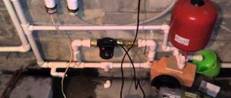
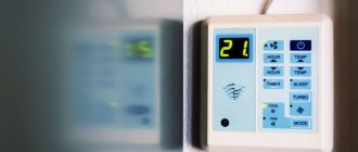
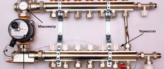
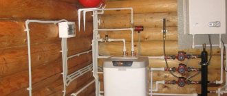
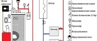
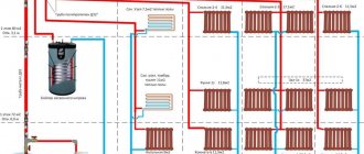
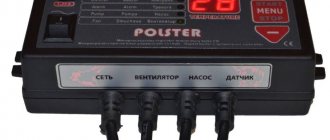
The boiler design provides for the presence of several control elements that control the outlet temperature of the coolant. A thermostat is a device that responds to changes in temperature. Often, in old or budget models of heating boilers, primitive types of this element are installed. They can only activate or deactivate the heating function. Therefore, in order to optimize the operation of the system, homeowners are thinking about how to make a temperature controller for the boiler with their own hands.
How to make a simple thermostat
The manufacture of a thermostat occurs in stages:
- Selecting the type and circuit of the device.
- Purchasing the necessary materials, tools and parts.
- Device assembly, configuration, commissioning.
The manufacturing stages of the device have their own characteristics, so they should be considered in more detail.
Necessary materials
Materials required for assembly include:
- Foil getinax or circuit board;
- Soldering iron with solder and rosin, ideally a soldering station;
- Tweezers;
- Pliers;
- Magnifier;
- Wire cutters;
- Insulating tape;
- Copper connecting wire;
- Necessary parts according to the electrical diagram.
Other tools or materials may be needed during the process, so this list should not be considered exhaustive or definitive.
Device diagrams
The choice of scheme is determined by the capabilities and level of training of the master. The more complex the circuit, the more nuances will arise when assembling and configuring the device. At the same time, the simplest schemes make it possible to obtain only the most primitive devices that operate with a high error.
Let's consider one of the simple schemes.
In this circuit, a zener diode is used as a comparator
The figure on the left shows the regulator circuit, and on the right is the relay block that turns on the load. The temperature sensor is resistor R4, and R1 is a variable resistor used to adjust the heating mode. The control element is a zener diode TL431, which is open as long as there is a load on its control electrode above 2.5 V. Heating of the thermistor causes a decrease in resistance, causing the voltage on the control electrode to drop, the zener diode closes, cutting off the load.
The other scheme is somewhat more complicated. It uses a comparator - an element that compares the readings of a temperature sensor and a reference voltage source.
A similar circuit with a comparator is applicable for adjusting the temperature of a heated floor.
Any change in voltage caused by an increase or decrease in the resistance of the thermistor creates a difference between the standard and the operating line of the circuit, as a result of which a signal is generated at the output of the device, causing the heating to turn on or off. Such schemes, in particular, are used to regulate the operating mode of heated floors.
Step-by-step instruction
The assembly procedure for each device has its own characteristics, but some general steps can be identified. Let's look at the build progress:
Preparing the device body
This is important because the board cannot be left unprotected. We are preparing the payment. If foil getinax is used, you will have to etch the tracks using electrolytic methods, having previously painted them with paint insoluble in electrolyte
A circuit board with ready-made contacts greatly simplifies and speeds up the assembly process. Using a multimeter, we check the performance of the parts and, if necessary, replace them with serviceable samples. According to the diagram, we assemble and connect all the necessary parts. It is necessary to ensure the accuracy of the connection, correct polarity and direction of installation of diodes or microcircuits. Any mistake can lead to the failure of important parts that will have to be purchased again. After completing assembly, it is recommended to carefully inspect the board again, check the accuracy of the connections, the quality of soldering and other important points. The board is placed in the case, a test run is carried out and the device is configured.
Possible problems when regulating the water temperature in the boiler
Adjusting the temperature in the boiler
When regulating the water temperature in the boiler, various emergency and even life-threatening situations can occur.
For example, it is important to prevent the heating element from turning on when there is not enough liquid inside the container.
This can lead to failure of the heating element and overheating of its insulator on the mounting bracket.
To avoid this, additional protection must be provided.
This can be done using a level or water pressure sensor in the boiler.
In the first case, it is best to use a float type with a permanent magnet and a reed switch.
But then difficulties will arise with the installation location of the device. When installing a pressure sensor, there are much fewer problems with choosing a location; if desired, it can be placed directly at the outlet of the container or at its inlet.
The second problem when regulating the water temperature in the boiler may be possible overheating in the event of a triac failure. You can again control the overload using a second pressure sensor set to a higher limit.
Or another temperature control module, assembled according to the same scheme, but set to overheat. Only in this case can the K554CA3A microcircuit control a transistor and an intermediate relay or a second optocoupler, which will open the power circuit of the optocoupler A3.
General concept of temperature controllers
Devices that record and simultaneously regulate a given temperature value are more common in production. But they also found their place in everyday life. To maintain the necessary microclimate in the house, water thermostats are often used. They make such devices with their own hands for drying vegetables or heating an incubator. Such a system can find its place anywhere.
In this video we will find out what a temperature regulator is:
In reality, most thermostats are only part of an overall circuit, which consists of the following components:
- A temperature sensor that measures and records, as well as transmits the received information to the controller. This happens due to the conversion of thermal energy into electrical signals recognized by the device. The sensor can be a resistance thermometer or a thermocouple, which have metal in their design that reacts to changes in temperature and changes its resistance under its influence.
- The analytical unit is the regulator itself. It receives electronic signals and reacts depending on its functions, after which it transmits the signal to the actuator.
- An actuator is a kind of mechanical or electronic device that, when receiving a signal from the unit, behaves in a certain way. For example, when the set temperature is reached, the valve will shut off the coolant supply. Conversely, as soon as the readings drop below the specified values, the analytical unit will give a command to open the valve.
Circuit with logic chip
This circuit differs from the previous one in that instead of a zener diode, it uses a K561LA7 logic chip. The temperature sensor is still a thermistor (designation VDR1), only now the decision to close the circuit is made by the logical block of the microcircuit. By the way, the K561LA7 brand has been produced since Soviet times and costs mere pennies.
For intermediate amplification of pulses, the KT315 transistor is used; for the same purpose, a second transistor, KT815, is installed in the final stage. This diagram corresponds to the left side of the previous one; the power unit is not shown here. As you might guess, it may be similar - with the KU208G triac. The operation of such a homemade thermal relay has been tested on boilers ARISTON, BAXI, Don.
Concept of temperature controllers
Products in this category are used to solve various problems. Based on the appropriate temperature threshold setting, power is supplied (turned off):
- heating in the cellar;
- heating the soldering station;
- boiler circulation pump.
From the examples given, the basic requirements for accuracy that a suitable thermostat circuit must provide are clear. In some situations it is necessary to maintain a given level no lower than ±1C°. To monitor operating parameters, an operational indication is needed. Load capacity is essential.
The listed features explain the purpose of typical functional units:
- the temperature value is recorded with a specialized sensor (resistor, thermocouple);
- the readings are analyzed by a microcontroller or other device;
- the actuator signal is sent to an electronic (mechanical) switch.
For your information. In addition to the parts discussed, the thermal relay circuit may contain additional components to supply power to an electric heater or other powerful load.
Types of temperature controller for heating boiler
According to the standard, a simple thermostat is installed in boiler units of any type, the task of which is to monitor the temperature of the coolant in the heating circuit. The owner of a house or apartment sets the optimal temperature regime at his own discretion, after which the thermoelement is switched on. It activates the gas burner or heating element, which leads to heating of the coolant.
Manufacturers supplement modern and expensive models of heating boilers with remote temperature controllers. Their functionality has been expanded, so they are able to:
- activate the heating system in accordance with the data of a weather-sensitive sensor located outside. That is, if the temperature drops below certain indicators, the regulator senses this and turns on the boiler in the house or apartment;
- constant monitoring of the temperature of the coolant in the heating circuit;
- a remote room temperature regulator for a gas boiler allows you to control the unit from anywhere in the house;
- It is possible to measure the temperature in any room using a remote sensor.
A weather-dependent temperature controller is ideal, but at the same time it is the most expensive. In addition, difficulties may arise with its installation and adjustment. But a weather-dependent sensor allows you to more effectively control the boiler and heating system, because it reacts to changes in the weather outside the window. Therefore, the rooms will always have an optimal microclimate.
If you install the temperature controller at a distance from the boiler unit, it will automatically transform into an external control module. Its main function is to scan thermocouple readings and turn on the heating remotely if the readings are lower than those set by the homeowner.
Thermostats also differ in their operating principle. The types are shown in the table below.
How to assemble a thermal relay yourself?
Heating control devices available for sale are quite reliable and do not cause any complaints. But at the same time, they cost money, and this does not suit those homeowners who have at least a little knowledge of electrical engineering or electronics. After all, understanding how such a thermal relay should function, you can assemble and connect it to the heat generator with your own hands.
Of course, not everyone can make a complex programmable device. In addition, to assemble such a model, it is necessary to purchase components, the same microcontroller, digital display and other parts. If you are new to this matter and have a superficial understanding of the issue, then you should start with some simple circuit, assemble it and put it into operation. Having achieved a positive result, you can move on to something more serious.
First, you need to have an idea of what elements a thermostat with temperature control should consist of. The answer to the question is given by the circuit diagram presented above, which reflects the operating algorithm of the device. According to the diagram, any thermostat must have an element that measures temperature and sends an electrical impulse to the processing unit. The latter’s task is to amplify or convert this signal in such a way that it serves as a command to the actuator - the relay. Next we will present 2 simple circuits and explain their operation in accordance with this algorithm, without resorting to specific terms.
How to make a thermostat with your own hands: step-by-step instructions
Let's look at how thermostats (thermal relays) with a 12 V air temperature sensor are made with your own hands. The device is assembled in the following sequence:
- First of all, you need to prepare the body. A used meter, for example Granit-1, will do.
- The circuit can be assembled on a board from the same meter. A potentiometer is connected to the direct input of the comparator (marked with a “+” sign), which allows you to set the temperature. To the inverse input (sign “-”) – temperature sensor LM335. If the voltage at the direct input is higher than at the inverse input, the comparator output will set to a high level (one) and the transistor will supply power to the relay, which will supply power to the heater. As soon as the voltage at the inverse input is greater than the direct one, the level at the output of the comparator will become low (zero) and the relay will turn off.
- To ensure a temperature difference, that is, the thermostat operates, for example, at 23 degrees, and turns off at 25, it is necessary to create a negative feedback using a resistor between the output and the direct input of the comparator.
- The transformer for powering the thermostat can be made from a coil from an old induction-type electric meter. It has space for a secondary winding. To get a voltage of 12 V, you need to wind 540 turns. They will be able to fit if you use a wire with a diameter of 0.4 mm.
A simple homemade thermostat
It is convenient to use the meter terminal block to turn on the heater.
Setting up the thermostat
As already mentioned, a thermostat based on the LM335 sensor does not need adjustment. It is enough to know the voltage supplied by the potentiometer to the direct input of the comparator.
It can be measured using a voltmeter. The required voltage value is determined by the above formula.
If you need, for example, for the device to operate at a temperature of 20 degrees, it should be 2.93 V.
If any other element is used as a temperature sensor, the reference voltage will have to be checked experimentally. To do this, you need to use a digital thermometer, for example, TM-902S. For precise adjustment, the thermometer and thermostat sensors can be connected using electrical tape, after which they are placed in an environment with different temperatures.
Thermostat made from scrap materials
The potentiometer knob must be rotated smoothly until the thermostat operates. At this moment, you should look at the scale of the digital thermometer and apply the temperature displayed on it to the scale of the thermostat. You can determine extreme points, for example, for temperatures of 8 and 40 degrees, and mark intermediate values by dividing the range into equal parts.
If you don’t have a digital thermometer at hand, the extreme points can be determined by water with ice floating in it (0 degrees) or boiling water (100 degrees).
When faced with choosing a heater, people discover that there are many types of devices, but you need to choose one. Ceramic heater for the home - subtleties of the right choice, review of models and prices.
Air humidity standards and methods for measuring it are presented in this topic.
Homemade external thermostat for boiler instructions
Below is a diagram of a homemade thermostat for a boiler, which is assembled using Atmega-8 and 566 series microcircuits, a liquid crystal display, a photocell and several temperature sensors. The Atmega-8 programmable microcircuit is responsible for compliance with the specified parameters of the thermostat settings.
Scheme of a homemade external thermostat for a boiler
Strictly speaking, this circuit turns the heating boiler on or off when the outside air temperature decreases (increases) (sensor U2), and also performs these actions when the temperature in the room changes (sensor U1). It is possible to adjust the operation of two timers, which allow you to adjust the time of these processes. A piece of circuitry with a photoresistor affects the process of turning on the boiler depending on the time of day.
Sensor U1 is located directly in the room, and sensor U2 is located on the street. It is connected to the boiler and installed next to it. If necessary, you can add an electrical part of the circuit that allows you to turn on and off high-power units:
The electrical part of the circuit allows you to turn on and off high-power units
Another thermostat circuit with one control parameter based on the K561LA7 chip:
Thermostat circuit with one control parameter based on the K561LA7 microcircuit
The thermostat is assembled on the basis of the K651LA7 microcircuit and is simple and easy to adjust. Our thermostat is a special thermistor that significantly reduces resistance when heating. This resistor is connected to the electricity voltage divider network. This circuit also contains resistor R2, with which we can set the required temperature. Based on this scheme, you can make a thermostat for any boiler: Baxi, Ariston, Evp, Don.
Another circuit for a microcontroller-based thermostat:
Circuit diagram for a thermostat based on a microcontroller
The device is assembled on the basis of a PIC16F84A microcontroller. The role of the sensor is performed by a digital thermometer DS18B20. A small relay controls the load. Microswitches set the temperature, which is displayed on the indicators. Before assembly, you will need to program the microcontroller. First, erase everything from the chip and then reprogram it, and then reassemble it and use it to your health. The device is not capricious and works fine.
The cost of parts is 300-400 rubles. A similar regulator model costs five times more.
A few final tips:
- although different thermostat options are suitable for most models, it is still desirable that the thermostat for the boiler and the boiler itself be made by the same manufacturer, this will greatly simplify the installation and operation process itself;
- before purchasing such equipment, you need to calculate the area of the room and the required temperature in order to avoid “downtime” of equipment and changes in wiring due to connecting devices of higher power;
- before installing the equipment, you need to take care of the thermal insulation of the room, otherwise high heat losses will be inevitable, and this is an additional cost item;
- if you are not sure that you need to purchase expensive equipment, then you can conduct a consumer experiment. Buy a cheaper mechanical thermostat, adjust it and see the result.
general description
A room thermostat for a gas boiler consists of 2 metal strips that are used as an electrical switch contact in the heating system circuit.
The nominal contact drops with a sharp increase in temperature, due to this the heating function is turned off. When the microclimate changes, the necessary valves are automatically turned on and the boiler starts working again.
The body of this device is usually made of white plastic. LEDs are used to illuminate the display. The range for determining the temperature in the house for many devices is within 0…+45°C.
In addition to saving money, there are many more advantages
Typically, thermostats for a gas heating boiler are purchased to save money. Reducing the room temperature by even a few degrees reduces gas consumption by 5%. Due to the fact that the device reduces the number of cycles of heating equipment switching on, the owners’ costs for utilities are also reduced. At the same time, the equipment additionally ensures the safety of all boiler elements, which do not wear out so much.
Advantages of using a thermostat:
- setting a comfortable microclimate - you can select up to 7 modes;
- savings on gas payments (about 20%);
- increasing the operating time of all elements of the heating system, including the circulation pump;
- prevents severe dry air and overheating in the house;
- reduction in the number of boiler equipment starts.
Individually specified temperature settings for the thermostat are especially relevant for families with children, when it is necessary to maintain a comfortable microclimate at all times, as well as for those people who are especially sensitive to temperature changes.
In this video you will learn how a wireless thermostat works:
Thermostat is not working - how to check?
At the same time, do not expect any major changes when replacing a thermostat from one model to another. There is an opinion that if the warm floor does not heat up, then it is worth changing the thermostat to a more expensive one, everything will change by itself.
The air temperature in the room will immediately rise, and where it was previously cold, it will become hot. Roughly speaking, the thermostat is like the speedometer in your car.
You can draw 300-350 km/h on the speedometer, but if the engine is not capable of producing such power, then you will not see this speed. If something is to blame for the poor performance of heated floors, then first of all look at the temperature sensor.
Checking the functionality of the thermostat is very simple. Supply it with 220V power and connect the remote sensor.
Next, instead of a warm floor, connect a regular incandescent light bulb to the thermostat. You begin to unscrew the knob, changing the temperature.
At a certain moment the light should light up.
Next, hold the temperature sensor in your hand and wait. When heat comes from your body, a working thermostat will turn on and the light bulb will go out.
If the sensor is hidden deep in the screed, you can warm up the area with a hairdryer and wait for the same effect. When the lamp does not react at all, this indicates a malfunction of the device.
The fastest way to repair in this case is to transfer the work from the floor sensor to the air sensor built into the housing.
The ends of the cable on the device from the floor temperature source will have to be unscrewed, and the settings of the device itself will have to be reset.
All this will work correctly provided that the thermostat is installed directly in the heated room.
If you have an electronic thermostat with PWM control, then using the above test method, it is not recommended to heat the sensor too quickly with an extraneous heat source. What does this mean?
Firstly, the thermostat will immediately detect an abnormal increase in heat and work ahead of time. Secondly, the “smart brains” of the device will forcibly turn off the heating for the next 20 minutes.
In this case, after just 5 minutes the temperature on the device’s display will be sufficient to turn on, and startup and contact closure will not occur. As a result, you will have doubts about the correct operation of the thermostat.
Therefore, the fast heat test is ideal for mechanical devices, but be careful with electronic ones.
Temperature hysteresis
Any regulator has tolerances for switching to temperature conditions laid down by the manufacturer. All that remains is to select the heating range.
If you set the room temperature to +20°C, and the hysteresis (lag) of the temperature sensor is 2 degrees, then automatic switching on will be at +18°C and switching off at +22°C. The room cools down gradually. When the temperature drops to the set hysteresis settings, indoor air heating is turned on.
The set temperature and the speed at which it is reached depend on many factors. Four of them are the main ones:
- coolant supply temperature;
- radiator material (cast iron, aluminum);
- concrete depth and pipe distance (for heated floors);
- heat loss - if the window is open or the room is poorly insulated, you will wait a long time for the desired temperature.
This is why hysteresis is so important. It evaluates the above aspects and gives a signal to turn on/off individually for each room. The specified allowances in the temperature mode allow you to correctly set the temperature for a comfortable feeling and avoid unnecessary energy costs.
Do-it-yourself thermostat for a heating boiler
The electronic thermostat can be programmed in any order.
Any modern heating boiler, regardless of the type of energy carrier used, must meet a number of requirements. This includes functionality, ergonomics, safety and the last quality, the relevance of which is growing every year - energy efficiency.
When choosing a boiler, the buyer thinks about how much the equipment will help save his budget. Reducing energy costs for heating a house will allow not only the high efficiency of the heating element, but also additional components of the heating system.
This is a thermostat and thermostat for an electric heating boiler, which control the operation of the boiler depending on the ambient temperature.
In addition, when it comes to electrical equipment, you need to think about purchasing a voltage stabilizer. It will not affect the energy efficiency of the heating device, but will also help save your budget by maintaining the operation of the electric boiler during power surges in the network.
What is a thermostat for electric heating boilers? Its main functions and types
A thermostat for an electric heating boiler, regardless of its operating principle, is equipment that is capable of controlling the operation of the heating element, depending on the temperature of the coolant in the home heating system or on the ambient temperature. A simplified diagram of the operation of any thermostat can be represented as follows: on the equipment panel, the user sets the desired temperature range of either the coolant in the heating circuit or the air in the room. The thermostat turns on the boiler.
The latter operates until the temperature of the coolant or air reaches the specified upper limit. Next, the thermostat turns off the heating element of the boiler. The heating automatically turns on when the room temperature does not drop below the limit specified on the thermostat. As a result, such automation for electric heating boilers without constant human control is capable of maintaining the desired microclimate in the house and allows for rational use of energy.
The thermostat for an electric heating boiler can be mechanical and electronic, wired and wireless. The price varies depending on the type of equipment. Each type of thermostat has its own advantages and disadvantages.
What is a safety group for heating and is it possible for the circuit to operate without it?
The question of whether a filter is needed for a gas boiler is covered in this article.
Mechanical thermostats
This is what a mechanical thermostat looks like.
They are based on either bimetallic plates or gas- or liquid-filled bellows. The latter work very simply. Under the influence of elevated temperature, the substance filling the bellows is capable of expanding, thereby blocking or opening (depending on the ambient temperature) the coolant flow, which, in turn, affects the operation of the main heating element. The boiler turns on/off.
A bimetallic thermostat for an electric heating boiler works as follows: the bimetal under the influence of high temperature is capable of bending, thereby opening the electrical network. As a result, the heating element of the electric boiler is turned off. As the temperature drops, the plate is leveled again, the circuit is closed, and the boiler resumes operation. As a result, the batteries become warm. By the way, vacuum heating radiators are an excellent solution if you want to save money.
The advantages of a mechanical thermostat for an electric heating boiler:
- ease of operation;
- low cost;
- durability;
- resistance to power surges in the network.
Equipment disadvantages:
- low sensitivity;
- deviation from the specified temperature range by 2-3 degrees.
Connection options
- To the heated floor system;
- To the heating element;
- To the heater.
Connecting a thermostat to a heated floor system
A standard underfloor heating thermostat is supplied with detailed instructions for connecting the device to the underfloor heating system. You can connect the TP yourself using the markings under the terminal blocks.
Underfloor heating mat
On the back of the regulator there are three pairs of terminal sockets for wires. The first pair is intended for connecting a two-core network cable. Socket “L” – phase, “N” – zero.
The second pair of sockets is intended for connection to the underfloor heating terminals – L1 and N1. The fifth and sixth terminals are used to connect to the temperature sensor.
Connecting the thermostat
Floor temperature regulators can be inserted into a socket box or mounted on the wall. The temperature sensor can be either built into the body of the device or installed at the end of an external cable.
In the first case, the air temperature inside the room is measured. In the second option, the sensor measures the degree of heating of the final floor covering.
Connecting the thermostat to the heating element
The thermostat must be connected to the electric heater through a magnetic starter. This is due to the fact that the power of the regulator is far from comparable to the power of heating elements.
A magnetic starter (MP) is needed when the thermostat controls several heating devices at once. The MP is cut into the phase wire in parallel with the thermostat. Adjustment of the operating modes of the heaters is carried out by a thermostat, the supply current passes through the MP. This makes it possible to use a three-phase power supply, which allows the operation of high-power heating elements.
Many TRs are equipped with electronic microprocessors, which additionally provide indicators of the level of humidity, pressure and time required to achieve the values of the specified parameters.
Connecting the thermostat to the heater
Thermostats can be mechanical or electronic. Recently, the second models have been actively displacing their mechanical counterparts. The use of modern electronics makes it possible to more effectively control the temperature in a given environment.
TRs for room heaters are built into heater housings or placed away from heating devices. The regulator, first of all, is connected to the electrical network, then through the control circuit it is connected directly to the temperature sensor.
Additional Information. In most cases, infrared heaters are connected to a thermostat via a magnetic starter. To connect the device correctly, you must strictly follow the instructions provided.
Features of how temperature control devices are connected depend on the type of heating devices. This can be a single-core or two-core connection of TP underfloor heating. The connection of a two-phase thermostat to three-phase current heating elements is carried out only through a magnetic starter. For water heating, the thermostat is embedded directly into the radiator. Each specific case has its own thermostat connection diagram.
The principle of operation of a storage boiler
Horizontal storage water heater
There are several types of storage boiler devices.
But in any case, they have a similar operating principle.
The design of the water heater consists mainly of a steel tank, but there are also plastic and copper ones, in which a heating element is installed - a heating element, a water intake valve, a temperature sensor, an outlet valve, etc.
Water enters through the inlet valve into the container, where, when a certain level is reached, the heating element turns on and heats it.
The heating element is powered through a switch controlled by a controller or electrical analog circuit.
When the heating element is turned on, a warning light on the boiler control panel lights up. In addition, there may be an additional indication signaling an emergency, which will disconnect the heater from the network if an emergency occurs.
But, as a rule, this is provided for in more expensive models of heaters; in budget ones, apart from the heating indication lamp and the fuse, there is nothing else.
By installing an electronic water temperature controller in the boiler, you can not only carry out flexible regulation, but also provide a number of protections and additional functions.
Methods for regulating water temperature in a boiler
Today there are a large number of ready-made electronic devices on sale that allow you to regulate and control the temperature of the water in the boiler. They can be roughly divided into two types:
- controller
- analog
The first type can be used in a smart home system, allowing you to regulate the water temperature in any convenient place and room. Thanks to their presence, you don't have to go to the boiler room.
The controller can operate both via wired and radio frequency communications, transmitting control commands to the control unit, and from there receive data about the current state of the control system.
Such devices have a control panel, display, convenient design, etc. But you can also buy cheaper thermostats, made in a housing for a DIN rail and installed in an electrical cabinet.
Making a temperature sensor with your own hands for controller-type water is not difficult. There are quite a large number of ready-made circuits with source codes for control programs for microprocessors that will provide a given water temperature, control its intake into a container, control pressure, leaks, etc.
In addition, with the help of such systems you can set a water heating schedule, which will greatly simplify your life. But we will look at simpler automatic control systems for the water heating process, which have proven themselves to be the best over years of active use.
Operating principle of a solid fuel boiler
To make a temperature sensor for a boiler with your own hands, you need to understand its operating principle. But considering that in such a heater it will be very difficult to control the intensity of the flame, which is comparable to the control system of an internal combustion engine, the best option would be to control the flow of water in the heating circuit.
In this case, temperature control is provided by turning on and off the engine, which pumps the system, which ensures its heating. Water is heated in the system by a water jacket, which covers the entire firebox and part of the chimney.
Methods for regulating water temperature in a heating system
To control the pump, you can use the same circuit as when regulating the water temperature in the boiler, because it already provides control of a low-resistance load. Since the engine has much less power, its on and off cycles can be controlled using a conventional relay with 220 V contacts and a current of 0.5 A. Typically, the power consumption of household pumps is more than 100 W.
Also, to ensure indoor temperature stability when using solid fuel boilers, it is a good idea to use three-way valves with thermostats in the heating circuit. The pump will pump the system, and the thermostat, if necessary, will add cold water to the hot circuit in order to achieve the specified temperature conditions on the radiators.
It’s clear how to control the flow of water in a heating system, but how to make your own thermostat to control the temperature on each radiator is not something to be clever about. It is easier and cheaper to use ready-made devices mounted directly on heaters.
Of course, you can go the other way, for example, if the house has a floor heating system. The flow of water can be controlled by solenoid valves, which will be switched by a controller or automatic device.
Mechanical devices for regulating the temperature of a heating boiler
A mechanical thermostat is a universal device that allows you to flexibly regulate the temperature on a specific heating device. Therefore, do-it-yourself installation of a temperature sensor is carried out directly at the inlet of the radiator or the entire circuit.
Modern thermostat models have fairly large limits for regulating the water temperature in the system, up to 820C. But such modes are usually not used, and the most optimal in our latitudes is a threshold at the limit of 650C.
Mechanical timers for heating boiler
Having a heating boiler at your disposal, it would be a universal sin not to equip it with automatic control devices. If you don’t have the desire or ability to make electronic devices, you can purchase a ready-made mechanical timer.
With its help, you can control and set the desired temperature, but in this case we are talking about an electric boiler with a heating element or an induction heater.
Electronic temperature sensor
Electronic thermostats have a slightly different principle for regulating the temperature of water in a heating system or boiler. For control, a thermal sensor is used, which can be semiconductor, wire or platinum.
The readings from it are read by the controller or the generated signal from it is sent to a circuit that, depending on the water temperature, turns on or off the heating element or circulation pump.
Installing such a temperature sensor with your own hands for water can be done in any convenient place, but not far from the boiler or boiler, or rather their active components. To control the water temperature in the heater, it is better to use rod-type sensors and install it in place of the former rheostat.
If the water heater is homemade, then the installation location of the sensor is selected based on convenience and correctness of the readings. The best option would be to place it in the central part of the container.
As for the placement of the temperature sensor in the heating system, it should be mounted on the return circuit and attached directly to the metal pipe. The advantage of electronic devices is that you can place multiple sensors and control the temperature in different rooms and do this more flexibly than using mechanical temperature controllers.
Device details
It was suggested above to use a thermistor as a temperature sensor, but this is not the only option.
In principle, any semiconductor element can be used in this capacity, since the characteristics of these parts always depend on temperature.
For example, the collector current of a conventional bipolar transistor increases when heated, which inevitably affects the operation of the amplifier stage (the transistor stops responding to the input signal due to a shift in the operating point).
Silicon diodes react to temperature changes in a similar way. At a temperature of +25 degrees, the voltage at the contacts of the free diode will be about 700 mV, and measurements on a permanent diode will show approximately 300 mV. If the temperature rises, the voltage will drop by about 2 mV with each degree.
However, all these elements have a significant drawback: thermostats assembled on their basis have to be set up with great difficulty, in other words, calibrated. After all, we only know approximately which element exhibits a characteristic at a particular temperature and how exactly it reacts to its fluctuations. It is much easier to work with temperature sensors produced by modern industry, which are calibrated at the stage of the production process.
The purchase of such a part will not cause a significant increase in the cost of the project. For example, an LM-335 analog temperature sensor from National Semiconductor costs only $1.
You can also use its modifications - the LM-135 and LM-235 sensors, although they are intended for use in military electronics and industry, respectively.
The LM-335 sensor contains 16 transistors and operates like a zener diode, in which the stabilization voltage depends on temperature.
Only in this case, all parameters are thoroughly known: for every degree on the absolute temperature scale (Kelvin) there is a voltage of 10 mV or 0.01 V.
Thus, if we want to know what the LM-335 stabilization voltage will be at a temperature of 20 degrees Celsius, we need to add 273 to this value (converted to Kelvin), and then multiply the result by 0.01 V. In this case, we get 2, 93 V. In production, the sensor is calibrated at a temperature of 25 degrees Celsius. The operating temperature range, within which the voltage changes linearly and according to the specified law (10 mV/degree), lies in the range from -40 to +100 degrees Celsius.
So, knowing the exact stabilization voltage of the LM-335 at a given temperature, all we have to do is set the appropriate voltage at the second input of the comparator - and the adjustment of the thermostat will be completed.
- The circuit based on the LM-335 temperature sensor should be arranged in such a way that a current of 0.45 to 5 mA flows through it. Note that the supply voltage of the thermostat does not have to be 12 V. This value was proposed only because it allows you to use a regular adapter, which can be bought inexpensively in a store, instead of a homemade power supply (step-down transformer + rectifier + stabilizer). If you do everything yourself, then the step-down transformer can be assembled based on an output voltage in the range of 3 - 15 V. The main thing is that the relay used in the circuit is designed for the same voltage.
- Next, select the resistance of the resistors of the voltage divider and variable resistor so that, at the existing voltage, the strength of the current flowing through the temperature sensor is within the specified limits. In principle, the sensor will remain operational at a current strength above 5 mA, but then it will get very hot, which is why the thermostat will not work correctly.
- As a comparator, you can use a microcircuit from the same manufacturer, produced under the brand name LM-311 (modifications for the military and industry - LM-111 and LM-211, respectively).
The relay used in the circuit is multi-contact (MKU type). In a simplified version (without battery), you can use a car relay
It is important to make sure that the amperage allowed for a given relay corresponds to the power of the heater
Quality materials to get the job done
You will need:
- potentiometer;
- integral stabilizer;
- network adapter;
- output device;
- thermostat.
Currently, any device can be bought in a store, but sometimes it is cheaper to make it yourself. Naturally, it is not worth soldering spare parts for electrical appliances, but it is quite possible to make an individual device suitable for the parameters of your cellar. The circuit diagram of such a device is simple. A certain temperature is maintained by turning on/off the heating element (heating element).
The temperature rises to a predetermined level, a special device - a comparator - is activated, and the heating element is turned off. In theory, such a device is easy to make, but when it comes to practical implementation, it becomes clear that not everything is so simple. Previously, calibration was performed as follows: the temperature sensor was immersed first in ice, then in boiling water.
To measure the readings, we took a voltmeter and a thermometer and set the desired response temperature. The process took a lot of time and did not give the best results. Today, buying a temperature sensor is not a problem. They are calibrated during manufacture, so there is no need to conduct any experiments. Modern technologies have made it possible to create a temperature sensor that transmits digital information. With the help of these devices, it is possible to measure the temperature at various points in the apartment - you control the temperature not only outside the window, but also inside the house.
Domestic or Chinese thermostat for incubator - review
The incubator can be purchased ready-made with all the necessary options. Especially for those who need individual parameters, there is a wide range of universal or specialized controllers on the market that solve one narrow or a whole range of problems.
Below we will consider ready-made offers of Russian and Chinese thermostats for incubators.
Domestic / from CIS countries
Controller "Dream-1". Produced by AKIP-DON (Ukraine). Thermoelement sensitivity (error) is up to 0.1°C. Temperature range – 0-85°C. It operates in circuits with an alternating voltage of 220V, with a current of up to 16 A. In addition to temperature, the controller can control the level of humidity (from 10 to 100%) and the rotation of trays with eggs (due to the operation and idle timer).
Thermostat for the Cinderella incubator. The device comes complete with a ready-made incubator, although many stores offer to purchase a thermostat separately. In total, there are two modifications: for operation from a 220V network and combined (both from 220V and from DC 12V). This temperature controller is also suitable for other domestic incubators, such as “Hawk”, “Cinderella”, “Nestka”, etc. The temperature measurement error is 0.2°C.
Temperature regulator TsTR-1 S. It has a low price and easy setup. Only the required temperature is set, the shutdown threshold is lower by 0.2°C. Works with active loads, for example, with heating elements or heaters with a power of up to 1 kW. There are no additional options other than heating.
Thermostat for incubator on Aliexpress
RINGDER RC-113M with PID controller. An interesting device with a reasonable price for such functionality. Operates on 220V AC mains. In the settings you can set the threshold for turning on and off separately. The accuracy of measurement by an external sensor is up to 0.1°C. The controller operates in accordance with the PID algorithm (smooth current control).
KETOTEK F0004 DC 12 V. Thermostat with digital display and measurement accuracy of 0.1°C. Operates only on a 12V DC power circuit (requires a separate converter when powered by 220V AC). An external temperature sensor is included in the kit. There is no device housing (provided in the form of a printed circuit board with all the necessary elements and connection connectors), which determines the low price of the unit.
Circuit with zener diode
A zener diode is the same semiconductor diode that passes current only in one direction. The difference from a diode is that the zener diode has a control contact. As long as the set voltage is supplied to it, the element is open and current flows through the circuit. When its value falls below the limit, the chain breaks. The first option is a thermal relay circuit, where the zener diode plays the role of a logical control unit:
As you can see, the diagram is divided into two parts. On the left side is the part preceding the relay control contacts (designation K1). Here the measuring unit is a thermal resistor (R4), its resistance decreases with increasing ambient temperature. The manual temperature controller is a variable resistor R1, the power supply to the circuit is 12 V. In normal mode, a voltage of more than 2.5 V is present at the control contact of the zener diode, the circuit is closed, the relay is turned on.
Advice. Any inexpensive commercially available device can serve as a 12 V power supply. Relay – reed switch brand RES55A or RES47, thermal resistor – KMT, MMT or similar.
As soon as the temperature rises above the set limit, the resistance of R4 will drop, the voltage will become less than 2.5 V, and the zener diode will break the circuit. Then the relay will do the same, turning off the power part, whose diagram is shown on the right. Here, a simple thermal relay for the boiler is equipped with a triac D2, which, together with the closing contacts of the relay, serves as an executive unit. The boiler supply voltage of 220 V passes through it.
