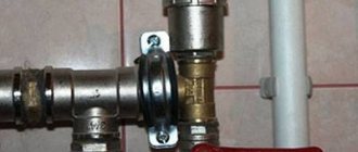
A three-way valve with a thermostat for heating is an important part of the room heating control system. The function of the valve is to maintain a comfortable thermal balance throughout the entire room by adjusting the temperature of the coolant in the heating circuit. The three-way valve does not reduce the flow of the working medium, but mixes several flows into one, thereby giving it the set temperature. Another purpose of a three-way valve is to distribute coolant across different circuits. So, heating radiators should receive water of one temperature, and the temperature of the coolant in the “warm floor” system should be different.
Three-way valve device
Structurally, it consists of two connected two-way valves in one body. But unlike them, the hot water flow is not completely blocked, but the intensity of its passage is regulated. Due to this, the temperature of the hot water changes.
- Valve main parts:
- frame;
- rod with locking washer or metal ball;
- fastening nuts (couplings).
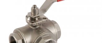
Valves with a stem allow automated control via an electromechanical drive. This allows you to automatically regulate the water temperature. The principle of operation of a ball valve can be compared to a kitchen faucet. They are used only in manually operated valves.
Please note: when choosing a faucet, you should pay attention to the material from which the body is made. Brass is lighter and more durable compared to cast iron.
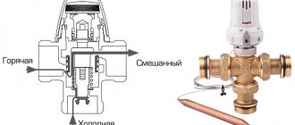
To understand what the thermo-mixing three-way valve of the most common saddle type consists of and how it works, you should study the diagram below.
Inside the brass body with three nozzles, 3 chambers are arranged using the casting method, the passages between which are blocked by poppet valves. They are fixed on one axis - a rod coming out of the body on the fourth side.
Types of Thermostatic Mixing Valves
- They differ in the way they are controlled. Valves can be roughly divided into:
- with manual control;
- with thermal head;
- with electric drive;
- hydraulic;
- pneumatic.
In a private home, an electric valve would be most acceptable. Sensors installed inside issue a command through the controller to the drive if the controlled water parameters change.
As a result, it becomes warmer, or vice versa, cooler. The thermo-mixing effect occurs automatically. It does not matter which boiler is installed in the system - gas or solid fuel.
If it is not possible to install an adjustable valve in the heating system, then the best solution in this case would be a valve with a thermal head.
Review of models and manufacturers of three-way valves
To make the right choice, you need to compare the parameters of different models, clarify information about the manufacturer and compare prices.
We offer a short overview of leading manufacturers.
Three-way valve with electric drive "Esbe"
Shut-off valves are distinguished by high quality, accuracy and affordable cost. In the manufacture of shut-off valves, a special brass alloy is used. Three-way valves are equipped with a servo drive.
We can highlight the VGR131 DN25 sample with an electric drive and this is an indicator of the highest quality of the manufacturer. Not all products are equipped with a servo or electric drive.
Three-way valve "Esbe"
Three-way valves "Navien"
The manufacturer "Navien" is known in the production of boiler equipment. Three-way valves are manufactured to regulate the flow of solid fuel equipment. The production of three-way valves and boilers in one place is a significant plus. This guarantees the efficient operation of the entire heating system.
Three-way valve "Navien"
Danfoss three-way valves
A fairly popular German company produces three-way valves with electric drive, which are easy to operate, durable and reliable. The taps are quite compact. The most important thing is to choose the right model, then the result will be achieved.
In addition to the above advantages, we can note:
- accuracy of temperature control;
- sustainability;
- simple maintenance;
- the work is fully automated.
Danfoss three-way valve
Installing a three-way valve in a heating system
The thermostatic mixer is installed in the heating system in the mixing unit with single or multi-circuit heat distribution. There may be several such circuits. The schematic diagram will not change. Only new elements will be added.
For example, a mixing unit. The presence of an additional coolant distribution circuit is its main distinguishing feature. Why is it needed? For connecting additional heat consumers. For example, heated floors.
When performing installation work to install the valve, you must remember that it is installed in front of the system pump. The performance of the entire system depends on compliance with this requirement.
When cutting into the valve, you need to make sure that welding waste (slag, drops of molten metal) does not get into it. It is also necessary to provide for the possibility of easy removal of the valve during its operation. This action will be required when periodically checking its performance.
Selecting a three-way valve for heating
To choose the right valve, you need to take into account many different nuances.
- First of all:
- number of circuits in the heating system;
- design feature of valve control;
- inlet pipe diameter;
- throughput of heating system pipelines;
- the material from which the valve is made.
It’s easy to figure out the number of heating system circuits yourself. With other moments of choice, everything is much more complicated. To find out how a three-way valve works and works, just delve into this issue.
And in order to correctly determine even its dimensions, it is necessary to have a concept in thermodynamics.
At its core, a 3-way valve is a valve with a thermostatic head. With an automated control drive, it is able to distribute hot water flows in the desired direction and in the required quantity.
Valves are not able to cope with such a task, which indicates the need for a three-way valve in the heating system. Using a valve in the system, there is no need to come up with some kind of remote control panel to control it. Everything is done without human intervention.
Design
The structure of a three-way valve includes two two-way valves combined in a single body. At the same time, they regulate the intensity of the coolant flow so that they can influence the temperature of hot water in radiators and underfloor heating pipes.
The thermostatic mixing valve consists of the following elements:
- metal case;
- steel ball or rod with locking washer;
- fastening couplings.
If the valve is equipped with a stem, it can be connected to an electromechanical actuator. Then the control of coolant flow and temperature can be automated. Manual valves are usually equipped with metal balls. The principle of operation of such devices is similar to the operation of a kitchen faucet.
How does a three-way valve work in a heating system?
The principle of operation of the valve is to mix water flows with different temperatures. Why do you need to do this? Without going into technical details, we can answer this way: to extend the life of the heating boiler and make it more economical.
A three-way valve mixes heated water with cooled water after passing through the heating devices and directs it back to the boiler for heating. Everyone can answer the question of which water to heat faster and easier - cold or hot.
Simultaneously with mixing, the valve also separates the flows. There is a natural desire to automate the management process itself. For this purpose, the valve is equipped with a temperature sensor with a thermostat. In this case, an electric drive works best here. The quality of functioning of the entire heating system depends on the drive device.
- Such a valve is installed in those places of the pipeline where it is necessary to split the circulation flow into two circuits:
- With constant hydraulic mode.
- With variable.
Typically, a constant hydraulic flow is used by consumers who are supplied with a high-quality coolant of a certain volume. It is regulated depending on quality indicators.
Variable flow is consumed by those objects for which quality indicators are not the main ones. The quantitative coefficient is important to them. That is, for them the supply is adjusted according to the required amount of coolant.
There are also two-way analogues in the shut-off valves category. What is the difference between these two types? The three-way valve works completely differently. In its design, the rod cannot block the flow with a constant hydraulic regime.
It is always open and adjusted to a certain volume of coolant. This means that consumers will receive the required amount in both quantitative and qualitative terms.
Essentially, the valve cannot shut off the supply to a circuit with constant hydraulic flow. But it is capable of blocking a variable direction, thereby allowing you to regulate pressure and flow.
If you combine two two-way valves, you get a three-way design. In this case, both valves must operate reversibly, that is, when the first one closes, the second one must open.
Types of three-way valves according to operating principle
- According to the principle of action, this type is divided into two subtypes:
- Mixing.
- Separating.
Just by the name you can understand how each type works. The mixer has one output and two inputs. That is, it performs the function of mixing two flows, which is necessary to lower the temperature of the coolant. By the way, this is an ideal device for creating the desired temperature in underfloor heating systems.
Regulating the temperature of the exhaust ceiling is quite simple. To do this, you need to know the temperature of the two incoming streams and accurately calculate the proportions of each in order to obtain the required temperature regime at the output. By the way, this type of device, if installed and adjusted correctly, can also work on the principle of flow separation.
A three-way separation valve splits the main flow into two. Therefore, it has two outputs and one input. This device is commonly used to separate hot water in hot water systems. Experts often install it in air heater trims.
In appearance, both devices are no different from each other. But if you look at their cross-sectional drawing, there is one difference that immediately catches your eye. The mixing device has a rod with one ball valve.
It is located in the center and covers the saddle of the main passage. In a separating valve there are two of these valves on one stem, and they are installed in the outlet pipes. The principle of their operation is as follows: the first closes one passage, pressing against the saddle, and the second at this time opens another passage.
- Modern three-way valves are divided into two types according to the control method:
- Manual.
- Electric.
More often you have to deal with a manual version, which is similar to a regular ball valve, only with three pipes - outlets. Electrical automatic systems are most often used for heat distribution in private housing construction.
For example, you can adjust the temperature in the rooms, distributing the coolant depending on the distance of the room from the heating boiler. Or ensure combination with a heated floor system. Devices with large cross-country ability are installed on heat pipelines between buildings.
Like any device, a three-way valve is determined by the diameter of the supply pipe and the coolant pressure. Hence GOST, which allows for certification. Failure to comply with GOST is a serious violation, especially when it comes to pressure inside the pipeline.
What is it and what is it for?
A three-way thermostatic valve is a mixer designed to change the temperature of the coolant in the heating system.
Purpose and scope of the device
Even if we take into account all the heat losses and arrange the heating circuit in full accordance with the thermal calculation data, it will not be possible to exclude a malfunction in the heat balance as a result of the influence of external factors (temperature changes, wind loads, etc.).
In order to respond to these processes in a timely manner, maintaining a comfortable temperature in the room for a long time, shut-off and control valves - three-way thermostatic valves - are installed in the main line.
They are used both in conventional radiator heating circuits and in underfloor heating systems, where they provide:
- Redirection (distribution) of coolant flows.
- Mixing coolant flows with different temperatures to obtain a given temperature level.
- Protection of the floor covering from overheating (in underfloor heating systems).
For the same purpose, three-way thermal valves are often used in hot water supply systems, where they perform the function of a familiar mixer.
Technical characteristics of three-way valves
The main technical characteristics of three-way thermomixing valves are:
- Throughput: consumption of cubic meters of water per hour at nominal temperatures (20°C) and pressure.
- Inner diameter of pipes.
The parameters of the throughput and internal sections of all 3 pipes of three-way valves are most often the same.
- Maximum operating pressure.
- Dynamic range of regulation (the ratio of the throughput of a thermal valve under conditions of a fully open shutter to the same indicator with a half-closed shutter).
On a note! The dynamic range of control of three-way thermostatic valves, such as 50:1 or 30:1, belongs to the class of average. The best control properties are shown by devices with a dynamic control range of 100:1.
Sizes and nominal operating pressure values of three-way thermostatic valves are regulated by GOST 28338-89 and 26349-84, respectively.
What materials are three-way thermal valves made of?
A variety of metals and alloys are used to produce three-way thermostatic valves. When it comes to industrial facilities, the following are most often used:
Cast iron. It has anti-corrosion properties and fairly high strength. However, if production and operation technologies are violated, cast iron products can be quite fragile.
Black carbon steel. The material is durable, cheap, but susceptible to corrosion. To smooth out the last drawback, three-way valves are nickel-plated and chrome-plated.
Stainless (alloy) steel. The parameters are higher due to the addition of an alloy of nickel and chromium. High strength, resistance to oxidation and corrosion provide products with a long service life. However, such thermal valves are significantly more expensive.
For heating systems of private houses, brass three-way valves are most often used. Their temperature regime is limited to 200 °C, but within the allowed temperature range, brass devices can work for quite a long time. No less popular are polymer products used in the corresponding heating or plumbing circuits.
More expensive are three-way valves made of bronze, which are not inferior to their brass counterparts in strength. Bronze products are usually installed in copper heating circuits.
Important! Sometimes on sale you can find shut-off valves made of silumin (a low-strength aluminum alloy with silicon). Outwardly, they are very similar to products made of stainless steel or brass, but at the same time they are several times cheaper and, unfortunately, last only as long as they are priced at.
The internal locking mechanism in household products may be made of ceramic (with the exception of three-way motorized thermal valves). Ceramic mechanisms are chemically inert and durable, but are extremely sensitive to the purity of the transported coolant. Its low quality is the reason for the rapid wear of ceramic elements.
Diagram of a heated floor with a three-way valve
Once you have an understanding of what a three-way valve is and what its work is, you can consider various connection diagrams, depending on the purpose and role of the element in heating the house.
- Thermal mixing valve is installed in the following cases:
- To protect a solid fuel boiler from the effects of condensation and temperature shock after sudden power outages.
- The coolant in the underfloor heating circuits should warm up to no more than 45 °C, which is ensured by a mixing unit with a three-way valve.
- To maintain the required coolant temperature in different places of the system.
- To protect a solid fuel heating unit from the formation of condensation, it is impossible to allow cooled water from the radiator network to be supplied to the boiler tank during its heating.
To do this, use the following boiler connection diagram with a bypass and a three-way mixing valve:
The scheme works like this. Until the heat generator warms up, water circulates in a small circle through the bypass. When the coolant in the return heats up to 50-55 °C, the valve begins to open and mix in cold coolant from the system. When the heater reaches operating mode, the bypass is closed and the entire flow goes through the radiators.
In a heated floor system, this element performs the same functions. The circulation pump circulates the coolant through the heating circuits until it begins to cool. As soon as this happens, the sensor and thermal head will operate, after which the three-way valve will begin to add hot water coming from the boiler to the closed circuit.
How to correctly install a heated floor manifold, pump and valve with your own hands is shown in the diagram:
The next example of the use and connection of this important part is the connection between a solid fuel heat generator and a buffer tank, which is a heat accumulator.
To warm it up completely quickly enough, the temperature of the supplied coolant must be from 70 to 85 ° C, which is not at all necessary in a radiator heating system. A three-way valve installed behind the container along with a separate circulation pump helps to lower it.
Important. When installing the mixing valve, remember that the pump should be located on the side where the three-way valve is always open.
A complex heating system of a large cottage can have many consumers connected via a hydraulic valve and a distribution manifold.
Moreover, coolant with a different temperature must be supplied to each of the circuits. The highest is needed for an indirect heating boiler, so there are no control valves on the supply line to it. The remaining consumers need a colder coolant, and therefore they are connected through three-way valves.
- Depending on the direction of flow, the thermostatic valve is available in two models:
- T-shaped or symmetrical design. With this connection, hot and cold water enters through the side holes, and after mixing, the liquid flows out through the central passage.
- L-shaped or asymmetrical design. In this case, hot water comes from one side, and cold water from below. Subsequently, the mixed flow exits from the second side passage.
Wiring diagram for a three-way mixing valve.
A mixing valve equipped with a thermostat is installed if it is necessary to ensure a stable temperature of the coolant.
- Considering the mixing unit, we can distinguish the following components in it:
- Check Valve;
- temperature sensor;
- circulation pump;
- three-way mixing valve.
Diagram of a mixing unit for heated floors
The connection diagram includes a circulation pump mounted on the supply. Then a temperature sensor is installed, which is necessary to determine the degree of heating of the incoming water.
After this comes the thermostatic valve. A check valve with an outlet is mounted on the “return”, which is connected to a pipe with circulating cooled liquid directed to the mixing valve.
- With a similar connection diagram, the coolant moves along the following route:
- Pumping hot water using a circulation pump into the equipped heated floor system. The coolant temperature can reach 80°C.
- Mixing with cold water through a three-way valve. As a result, the desired temperature is achieved.
- Distribution of coolant through underfloor heating pipes.
- The return of the cooled water to the “return”, from where it is taken into the three-way valve for subsequent mixing with the hot liquid.
With such a connection, the temperature sensor regulates the degree of heating of the water entering the water circuit. There are other ways to control. The most ineffective is the manual method, when you need to change the flow by turning the handle.
There is a control option using a servo drive, commands to which are received from the controller in accordance with signals received from sensors.
Diagram of components based on three-way mixing and thermostatic valves for heated floors.
The thermostatic tap plays an important role when installing a water heated floor. By preventing the coolant entering the pipes from overheating, it saves fuel. In addition, safety is ensured during the operation of a rather complex heating system and the trouble-free service life is extended.
Installation diagram of a three-way separating valve
Provides quantitative control for the consumer - by changing the coolant flow. It is used if, according to the operating conditions of the heat source, it is permissible to bypass the coolant into the return pipeline and it is not allowed to stop circulation in the source circuit.
This scheme for installing a three-way valve has been widely used in water and air heating units connected from an autonomous boiler room. To link hydraulic circuits, the pressure loss at the balancing valve in the bypass line must be equal to the pressure loss at the consumer.
This installation diagram for a three-way valve is intended for connection to a pipeline with excess pressure. The coolant circulation in the consumer circuit is ensured due to the excess pressure created by the circulation pump in the heat source circuit.
Installation diagram of a three-way separating valve
Schemes for installing a three-way mixing valve for separation
Provides quantitative control at the consumer using a three-way mixing valve. It is used if, according to operating conditions, cessation of flow in the source circuit is not allowed, but the bypass of coolant from the supply pipeline to the return pipeline is acceptable.
Similar schemes for connecting three-way valves have become widespread in the piping of air heaters and air coolers, as well as in water heating units installed in autonomous boiler houses.
It is recommended to install a balancing valve with a hydraulic resistance equal to the consumer resistance on the mixing pipe of the three-way valve. Circulation through the consumer and bypass is carried out due to excess pressure in the source circuit.
With the correct selection of the valve and hydraulic coupling of the bypass with the consumer circuit, the flow through the heat source is constant, and in the consumer circuit it is variable.
Connection diagram of a three-way mixing valve for flow separation to a pressure manifold
Since the water flow moves in the opposite direction to the direction of flow in the mixing valve, some valves may increase noise and vibration, as well as reduce the permissible pressure drop across the valve.
Installation diagram of a three-way mixing valve for separation to a hydraulic arrow When connecting a unit with a three-way separation valve to a heat source directly or to a free-flow collector, it is necessary to install a circulation pump in the supply or return pipeline. The pump can be common to several circuits.
The connection diagram of a three-way valve dividing the flow with an additional bypass in the consumer circuit parallel to the mixing line is used provided that the temperature regime of the source exceeds the temperature regime of the consumer.
The peculiarity of this scheme is that the flow rates in the source and consumer circuits will be constant, and overheated coolant will not flow to the consumer. The consumer will be provided with quality regulation. For this circuit to work, it is necessary to install a pump in the consumer circuit and in the source circuit.
If gas is available, the most economical way to heat a private home is a double-circuit gas boiler.
Or, as an option, an electric boiler.
Main design features and functions of the device
Having a rough idea of the operating principle of a three-way valve, it is better to study in detail the operation of this mechanism. The name “three-way” defines the main function of the device - water of various origins enters the valve through two inputs:
- hot coolant from the supply pipe connected to the heating device or to the riser of the central heating system;
- cooled water returning after passing through the water circuit.
Mixing with each other in the valve in a certain proportion, the flows exit through the third pipe, having a given temperature. The valve works constantly, since the principle of cyclic operation of heated floors is based on mixing hot water with the cooled coolant: heating - heat transfer - mixing - heat transfer - mixing.
The process of mixing two coolant flows of different temperatures must be constantly monitored, preferably in automatic mode. Otherwise, the intensity of heat exchange between the heated floor and the room air will not be tied to changes in the temperature in the room, and you will have to change the heating temperature of the coolant manually as necessary.
A temperature-sensitive head allows for automatic mixing of hot coolant, regulating the valve capacity depending on the temperatures of the mixed liquids to obtain a given output value.
Depending on the purpose and operating conditions, various types of three-way valves are used.
1. Heating systems
For a heating system with radiators, powered by an autonomous boiler, the simplest type of device is used. They are inexpensive and have a relatively simple design, which allows you to install them yourself. In this case, the mixing volume is adjusted manually.
2. Hot water systems
In hot water supply systems, three-way valves are used to maintain safe water temperatures in the communication system, eliminating the possibility of burns. The design of such devices is also quite simple and understandable. Such devices differ from valves for heating systems by the presence of a special protective block that shuts off hot water if there is no cold water in the water supply.
3. Warm water floors
Devices of this type are the most complex, as they are designed to maintain a given temperature of the coolant in heating circuits in relation to the air temperature in the room. The use of such devices in a mixing unit allows you to regulate the heating intensity of your home automatically,
Layout diagram of the mixing unit and location of the three-way valve in it
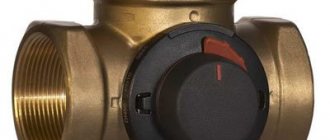
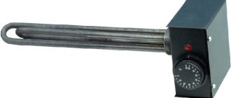
Three-way valve model with adjustment scale
For heated floors, the faucet is equipped with an adjustment handle and a measuring scale, which is used to adjust the device.
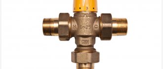
Three-way mixing valve with thermal head
The valve with thermostat guarantees the practicality and efficiency of the system. Three-way heating valves are designed to regulate heat flow, which ensures indoor comfort and economical use.
Before proceeding with the design of the heating system, a thermal calculation is performed. Based on its results, the appropriate power and type of heating devices are selected that can maintain the optimal temperature in the room.
The area of the room is taken into account, and then possible heat losses are analyzed. Based on this, the performance of the heating system necessary to create a comfortable microclimate in the rooms is calculated. After that, a heat balance is compiled for all rooms.
However, these calculations are made under specific conditions, which may change during operation.
- The factors affecting the operation of the radiator are different:
- temperature changes outside;
- solar Activity;
- wind force;
- the presence of household appliances that generate heat.
As a result, the calculated temperature balance is disrupted and the room becomes hot. However, it is impossible to remove parts of the radiator from the room or muffle thermal radiation. Thus, there is a need to manage the energy generated by heating devices in order to maintain a comfortable microclimate in the room.
- There are two ways to regulate the energy released by the radiator:
- Qualitative change in the properties of the radiator.
- Quantitative regulation of heat generated.
- In both cases, manipulations with the liquid circulating through the pipes are necessary.
In cases where you cannot influence the temperature of the water supplied to the radiator, you can regulate its quantity. For this you need to buy three-way valves for heating with a thermostat.
These devices make it possible to limit the amount of water passing through the radiator, and as a result, with the same radiator area, more or less heat will flow into the room, of course, within limits limited by the power of the system.
Three-way mixing valve with thermostat
A three-way valve for the heating system and a temperature controller installed on the radiator can be used separately, however, in autonomous heating systems of modern apartments and private cottages, a combined method is often used to increase efficiency.
Thus, it is advisable to purchase a three-way valve for heating with a thermostat.
It is important to consider that the operating principle of a three-way mixing valve allows you to increase or decrease the radiator temperature only within established limits. These limits are dictated by the technical characteristics of the heating device, namely, the value of its maximum heat transfer, and depend on each specific radiator.
Principle of operation
The three-way valve is equipped with three pipes for connecting lines. A valve is installed between them to regulate the water supply to two of the three branches. Depending on the orientation of the tap and its connection, it performs two functions:
- mixing two coolant flows into one outlet;
- division from one line to two outputs.
A three-way valve, like a four-way valve, does not shut off the channels connected to it, but only redirects the liquid from the inlet to one of the outlets. Only one of the exits can be closed at a time, or both can be partially blocked.
In the simplest version, radiators are directly connected to the boiler, in series or in parallel. It is impossible to adjust each radiator separately according to thermal power; it is only permissible to regulate the temperature of the coolant in the boiler.
In order to still regulate each battery separately, you can insert a bypass parallel to the radiator and after it a needle-type regulating valve, with which you can control the amount of coolant passing through it.
A bypass is needed to maintain the overall resistance of the entire system, so as not to disrupt the operation of the circulation pump.
However, this approach is very expensive to implement and difficult to operate.
The three-way valve actually combines the connection point for the bypass and control valves, making the connection compact and easy to operate. In addition, due to smooth adjustment it is easier to achieve the target temperature in a limited circuit containing one or two radiators in a specific room.
If you limit part of the coolant current from the boiler and supplement it with return water returning from the radiator to the boiler, the heating temperature decreases. At the same time, the boiler continues to operate in the same mode, maintaining the set water heating; the water circulation speed in it does not decrease, but fuel consumption decreases.
If one circulation pump is used for the entire heating system, then it is located on the side of the boiler in relation to the inclusion of the three-way valve. It is installed at the return inlet of the boiler, through which already cooled water from the radiators flows, acting as a flow separator.
Hot coolant from the boiler is supplied to it at the inlet; depending on the valve setting, the flow is divided into two parts. Some of the water goes to the radiator, and some is immediately discharged in the reverse direction. When maximum thermal power is needed, the valve is moved to its extreme position, in which the inlet and outlet leading to the radiators are connected.
If heating is not needed, then the entire volume of coolant flows through the bypass into the return line, the boiler only works to maintain the temperature in the absence of real heat transfer
The disadvantage of such a connection is that it is difficult to balance the heating so that the same amount of coolant flows into each branch and to each radiator; in addition, when connected in series, the water that has already cooled down reaches the outer radiators.
For heated floors
In multi-circuit systems, the easiest way to solve the problem of uneven heat distribution is to use a collector group with circulation pumps on each individual circuit
This is especially important in houses with two or more floors and a large number of radiators or with heated floors
The three-way valve works to mix the two flows. The line from the boiler is connected through one input, and the return pipe through the second. Mixing, the water flows to the outlet connected to the heat exchanger.
This connection diagram is especially relevant when connecting a heated floor.
It makes it possible to limit the maximum water temperature in the circuit, which is especially important, given the maximum permissible value of 35ºC at a coolant temperature from the boiler of 60ºC and above
Water circulation in the underfloor heating pipes is constantly maintained, which is necessary for uniform heating without distortions. In fact, hot water from the boiler is supplied only to heat the cooling coolant in the heated floor circuit, and the excess is discharged back to the boiler.
Thus, even in high-temperature heating, where the boiler heats water to 75-90ºС, it is possible to install heated floors with heating at 28-31ºС.
Servo drive for three way valve
A servo is an electric motor controlled through negative feedback. In this case, the negative feedback will be a shaft angle sensor, which stops the shaft movement when the desired angle is reached.
For clarity, let’s look at the servo drive device according to the figure:
- As you can see, the following components are located inside the servo drive:
- Electric motor.
- A gearbox consisting of several gears.
- The output shaft by which an actuator rotates a valve or other device.
- The potentiometer is the same negative feedback that controls the angle of rotation of the shaft.
- Control electronics, which is located on the printed circuit board.
- The wire through which the supply voltage (220 or 24 V) and the control signal are supplied.
Let's now take a closer look at the control signal. The servo drive is controlled by a pulse signal with variable pulse width. For those who don’t know what we’re talking about, here’s another picture:
That is, the pulse width (in time) determines the magnitude of the shaft rotation angle. Setting up such control signals is not trivial and depends on the specific drive. The number of control signals depends on how many positions the output shaft can occupy.
The servo drive can be two-position (2 control signals), three-position (3 control signals) and so on.