Energy saving is now the most popular topic on the Internet. Of course, everyone wants to save money, especially in the current economic conditions. Calculation of heat losses plays the most important role in this case. Heat loss in the simplest sense is the amount of heat that is lost by a room, house or apartment. They are measured in Watts. Heat losses occur in the house due to the difference in external and internal air temperatures.
During the transitional and cold period of the year, the temperature on the streets drops, and the temperature difference between indoor air and outdoor air increases. And as we already mentioned, no one has canceled the Second Law of Thermodynamics, so the heat from your houses and apartments tends to leave it and warm the cold environment. To reduce these heat losses, houses are insulated in various forms, from polystyrene foam and ventilated facades to modern thermal insulation materials in the form of putty. The main task in our profession is to maintain comfortable microclimate parameters in the room. And first of all, we calculate heat losses to compensate for them.
Brief description of the heating network
To cover heat loads, a production heating boiler house is used, the main fuel of which is natural gas.
The boiler room produces
- steam for technological needs - all year round
- hot water for heating needs - during the heating season and
- hot water supply - all year round.
- The project provides for the operation of the heating network according to a temperature schedule of 98/60 degrees. WITH.
The heating system connection diagram is dependent.
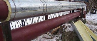
Heating networks that ensure the transfer of thermal energy for the heating needs of the entire village and hot water supply to its right-bank part are installed in above-ground and underground versions.
The heating network is branched and dead-end.
The year of commissioning of heating networks was 1958. Construction continued until 2007.
Thermal insulation completed
- glass wool mats 50 mm thick, with a covering layer of rolled material,
- extruded polystyrene foam type TERMOPLEX 40 mm thick, with a covering layer of galvanized sheet and polyethylene foam 50 mm thick.
During operation, some sections of the heating network were repaired with the replacement of pipelines and thermal insulation.
Vulnerable areas of the floor
An uninsulated ceiling transfers a significant portion of the heat to the foundation and walls. This is especially noticeable if the heated floor is installed incorrectly - the heating element cools down faster, increasing the cost of heating the room.
Floor on thermal imager
To ensure that the heat from the floor goes into the room and not outside, you need to make sure that the installation follows all the rules. The main ones:
- Protection. A damper tape (or foil polystyrene sheets up to 20 cm wide and 1 cm thick) is attached to the walls around the entire perimeter of the room. Before this, the cracks must be eliminated and the wall surface leveled. The tape is fixed as tightly as possible to the wall, isolating heat transfer. When there are no air pockets, there are no heat leaks.
- Indent. There should be at least 10 cm from the outer wall to the heating circuit. If the heated floor is installed closer to the wall, then it begins to heat the street.
- Thickness. The characteristics of the required screen and insulation for underfloor heating are calculated individually, but it is better to add a 10-15% margin to the obtained figures.
- Finishing. The screed on top of the floor should not contain expanded clay (it insulates heat in the concrete). The optimal thickness of the screed is 3-7 cm. The presence of a plasticizer in the concrete mixture improves thermal conductivity, and therefore the transfer of heat into the room.
Serious insulation is important for any floor, and not necessarily with heating. Poor thermal insulation turns the floor into a large “radiator” for the ground. Is it worth heating it in winter?!
Important! Cold floors and dampness appear in the house when the ventilation of the underground space is not working or not done (vents are not organized). No heating system can compensate for such a deficiency.
We determine actual heat losses in heating networks
We proceed from the fact that heat losses in heating networks do not depend on the speed of water movement in the pipeline, but depend on
- pipe diameter,
- coolant temperature,
- thermal insulation material and
- state of thermal insulation.
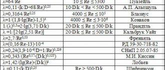
Stationary thermal conductivity of a cylindrical wall - description of the calculation method
A cylindrical wall is understood as a pipe of infinite length with an internal radius R1 (diameter D1) and an external radius R2 (diameter D2).
Constant temperatures t1 and t2 are set on the wall surfaces. Heat transfer is carried out only by thermal conductivity, the outer surfaces are isothermal (equipotential) and the temperature field changes only along the thickness of the pipe wall in the radial direction.
The heat flow passing through a cylindrical wall of unit length is denoted by ql and is called linear heat flow, W/m:
where λ is the thermal conductivity coefficient of the material under study, W/(m∙K);
D1, D2 – respectively internal and external diameters of the cylindrical layer of material;
t1, t2 – average temperatures of the inner and outer surface of the cylindrical layer of material.
Heat flow, W:
where l is the length of the pipe, m.
Let us consider the thermal conductivity of a multilayer cylindrical wall, consisting of n homogeneous and concentric cylindrical layers with a constant thermal conductivity coefficient and in each layer, the temperature and diameter of the inner surface of the first layer are equal to t1 and R1, on the outer surface of the last nth layer – tn+1 and Rn+ 1.
The linear heat flow of a cylindrical wall ql is a constant value for all layers and is directed towards lower temperatures, for example, from the inner layer to the outer one.
Writing down the value ql for each arbitrary i-th layer and transforming this equation, we have
Since the heating network has three different types of insulation, we calculate the heat losses of pipelines for each type separately, as well as the case without pipeline insulation to assess heat losses in damaged sections of the heating network.
Next, we calculated heat losses in heating networks with different types of thermal insulation.
In the example that follows, the calculation of heat losses in a heating network with thermal insulation made of foamed polyethylene.
Heat loss through sewerage
During the heating season, the water entering the house is quite cold, let’s say it has an average temperature of +7°C. Water heating is required when residents wash dishes and take baths. The water in the toilet cistern is also partially heated by the ambient air. Residents flush all the heat generated by water down the drain.
Let's say that a family in a house consumes 15 m3 of water per month. The specific heat capacity of water is 4.183 kJ/(kg×°C). The density of water is 1000 kg/m3. Let’s assume that on average the water entering the house heats up to +30°C, i.e. temperature difference 23°C.
Accordingly, per month heat loss through the sewerage system will be:
1000 kg/m3 × 15 m3 × 23°C × 4.183 kJ/(kg×°C) = 1443135 kJ
1443135 kJ = 400.87 kWh
During the 7 months of the heating period, residents pour into the sewer:
7 × 400.87 kWh = 2806.09 kWh
Calculation of thermal energy losses in heating networks with thermal insulation made of foam polyethylene
The example shows calculations for three sections.
| Plot number | Length of the section, m | Purpose of the pipeline | Outer diameter of water pipelines, mm | Wall thickness, mm | Coef. Thermal conductivity of steel, W/m*degree | Insulation thickness, mm |
| 1 | 41,2 | from | 426 | 9 | 55 | 50 |
| 41,2 | from | 426 | 9 | 55 | 50 | |
| 41,2 | guards | 108 | 4 | 55 | 50 | |
| 2 | 152 | from | 426 | 9 | 55 | 50 |
| 152 | from | 426 | 9 | 55 | 50 | |
| 3 | 274,3 | from | 426 | 9 | 55 | 50 |
| 274,3 | from | 426 | 9 | 55 | 50 |
Table continuation:
| Plot number | Coef. Thermal conductivity of insulation, W/m*degree | Coolant temperature, °C | Temperature on the surface of the insulated pipe, °C | Specific heat loss per 1 m, W | Total heat loss, W |
| 1 | 0,05 | 68 | 6 | 83,1 | 3 425 |
| 0,05 | 53 | 6 | 63,0 | 2 596 | |
| 0,05 | 73 | 6 | 28,9 | 1 191 | |
| 2 | 0,05 | 68 | 6 | 83,1 | 12 634 |
| 0,05 | 53 | 6 | 63,0 | 9 578 | |
| 3 | 0,05 | 68 | 6 | 83,1 | 22 800 |
| 0,05 | 53 | 6 | 63,0 | 17 284 |
In total, the heating network consists of 56 sections.
Based on the results of calculations, the total heat losses in heating networks with insulation made of foamed polyethylene are 864,687 W, from thermoplex 730,602 W, from glass wool 864,687 W.
Glass insulation
Glass itself is a serious source of heat loss. When choosing a double-glazed window, you should pay special attention to the number of chambers and the type of glass (regular, energy-saving, noise-proof, sun-protective, impact-resistant). To improve the thermal insulation properties of existing windows, you can stick a special heat-saving film on them, which has a high light transmittance. In case of strong winds, you can also apply bubble wrap.
If there is a shading film on the windows, it is better to remove it, because... it prevents the penetration of sunlight.
Total heat losses in heating networks
As a result of the inspection of the heating network, it was established that
- 60% of heating network pipelines are insulated with glass wool with 70% wear,
- 30% extruded polystyrene foam type TERMOPLEX and
- 10% polyethylene foam.
| Thermal insulation | Total losses of thermal energy in heating networks, taking into account the percentage of coverage and wear, kW | Calculation of heat losses in heating networks, taking into account the percentage of coverage and wear, Gcal/hour |
| Glass wool | 803,589 | 0,69092 |
| TERMOPLEX | 219,180 | 0,18845 |
| Foamed polyethylene | 86,468 | 0,07434 |
| Total: | 1109,238 | 0,95372 |
Heat loss through ventilation
Approximate volume of available air in the house (I do not take into account the volume of internal walls and furniture):
10 m x 10 m x 7 m = 700 m3
Air density at +20°C is 1.2047 kg/m3. The specific heat capacity of air is 1.005 kJ/(kg×°C). Air mass in the house:
700 m3 × 1.2047 kg/m3 = 843.29 kg
Let's say all the air in the house changes 5 times a day (this is an approximate number). With an average difference between indoor and outdoor temperatures of 28 °C over the entire heating period, the following thermal energy will be consumed on average per day to heat the incoming cold air:
5 × 28 °C × 843.29 kg × 1.005 kJ/(kg×°C) = 118650.903 kJ
118650.903 kJ = 32.96 kWh (1 kWh = 3600 kJ)
Those. During the heating season, with a fivefold replacement of air, the house through ventilation will lose an average of 32.96 kWh of thermal energy per day. Over 7 months of the heating period, energy losses will be:
7 × 30 × 32.96 kWh = 6921.6 kWh
Calculation of pipeline wear
The average age of heating network pipelines is 36.5 years.
During a physical examination, it was found that the residual service life for it is assumed to be 15 years, while the standard service life is 25 years. Pipeline wear is determined as follows:
36.5/(36.5+20) x (100-15) = 54.9115%
Look at an example of a survey before upgrading a boiler house and heating network.
Checking windows for leaks
Up to 40% of heat escapes through windows. If the windows are old, wooden and it is not possible to replace them with modern double-glazed windows, then to insulate them you can use insulation from available thermal insulation materials. Even duct tape will do. It is also necessary to check the window closing mechanisms and adjust if necessary. It is recommended to use three-chamber double-glazed windows for glazing windows.
Thermal imaging inspection of the heating network
The calculation of heat losses in heating networks was supplemented by thermal imaging examination.
Thermal imaging inspection of the heating network helps to detect local defects in pipelines and thermal insulation for subsequent repair or replacement.
The thermal insulation of the pipelines containing the coolant is damaged. The maximum temperature in open areas was 59.3 °C
Partial destruction of thermal insulation of pipelines with coolant. The maximum temperature in open areas was 54.5 °C
Partial destruction of thermal insulation of pipelines with coolant. The maximum temperature in open areas was 56.2 °C
The thermal insulation of the pipelines containing the coolant is damaged. The maximum temperature in open areas was 66.3 °C
Open sections of pipelines without insulation.
Open sections of pipelines without insulation.
Partial destruction of thermal insulation of pipelines with coolant.
Partial destruction of thermal insulation of pipelines with coolant. The maximum temperature in open areas was 62.5 °C
Partial destruction of thermal insulation of pipelines with coolant. The maximum temperature in open areas was 63.2 °C
Partial destruction of thermal insulation of pipelines with coolant. The maximum temperature in open areas was 63.8 °C
Partial destruction of thermal insulation of pipelines with coolant. The maximum temperature in open areas was 66.5 °C
Partial destruction of thermal insulation of pipelines with coolant. The maximum temperature in open areas was 63.5 °C
Partial destruction of thermal insulation of pipelines with coolant. The maximum temperature in open areas was 69.5 °C
Partial destruction of thermal insulation of pipelines with coolant. The maximum temperature in open areas was 62.2 °C
Partial destruction of thermal insulation of pipelines with coolant. The maximum temperature in open areas was 52.0 °C
Open sections of pipelines without insulation. The maximum temperature in open areas was 62.4 °C
Partial destruction of the thermal insulation of pipelines with coolant under the influence of the environment.
Learn about inspection of water supply systems.
Partial destruction of the thermal insulation of pipelines with coolant under the influence of the environment.
Partial destruction of thermal insulation of pipelines with coolant. The maximum temperature in open areas was 67.6 °C
Partial destruction of thermal insulation of pipelines with coolant. The maximum temperature in open areas was 58.8 °C
Partial destruction of the thermal insulation of pipelines with coolant under the influence of the environment.
Door seal
A fairly large amount of heat “leaves” through the entrance doors if they are not closed tightly and there are gaps between the door frame and the wall. The cracks must be sealed using flexible sealant, and a sealant must be installed on the door itself. Losses will be significantly reduced if there is an additional vestibule in front of the front door or a second door is installed.
Thermal imaging inspection of the heating network
Areas of the object without defects, anomalies and heat losses
The pipelines are completely insulated, heat losses correspond to standard losses.
The pipelines are completely insulated, heat losses correspond to standard losses.
The pipelines are completely insulated, heat losses correspond to standard losses.
The pipelines are completely insulated, heat losses correspond to standard losses.
The pipelines are completely insulated, heat losses correspond to standard losses.
The pipelines are completely insulated, heat losses correspond to standard losses.
The pipelines are completely insulated, heat losses correspond to standard losses.
Thermal imaging examination from RUB 15,000.
Find out in detail
Instruments and controls
The quality control of the thermal insulation of structures was carried out using a “testo 871” thermograph (thermal imager).
During the thermal inspection, the following equipment was additionally used:
- thermohygrometer Testo 622,
- heat flux density and temperature meter ITP-MG4.03 “POTOK”,
- Thermal anemometer Testo 405.
Technical characteristics of Testo 871
| SI name | Thermal imager | |
| Manufacturer | testo 871 | |
| Brand SI | 871 | |
| Serial number | 1008266 | |
| No. in the State Register of Measuring Instruments | 44367-10 | |
| Specifications | ||
| Detector size, pixels | 240×180 | |
| Image quality NETD, mK | 90 | |
| Error | ±2 °C or ±2% | |
| Temperature range, °C | -30…+650 | |
| Operating temperature, °C | -15 … +50 | |
| Probe type | infrared | |
| Image storage type | removable SD memory card | |
Technical characteristics of Testo 622
| SI name | Thermohygrometer | |
| Manufacturer | testo | |
| Brand SI | 622 | |
| Serial number | 39501565/005 | |
| No. in the state register of measuring instruments | 35319-07 | |
| Specifications | ||
| measurement range | 300…1200.0 hPa | |
| Humidity measurement error (at 25±5°С), % | no more than ±3 | |
| Temperature measurement range, °C | -10…+60 | |
| temperature measurement error, °C | no more than ±0.4 | |
| Dimensions | 185 x 105 x 36 mm | |
Technical characteristics of Testo 405
| SI name | Thermal anemometer | |
| Manufacturer | testo | |
| Brand SI | 405 | |
| Serial number | 41518249/410 | |
| Flow rate | ||
| Measuring range | 0 … +99990 m³/h | |
| Thermal anemometer | ||
| Measuring range | 0 … 5 m/s (-20 … 0 °C) 0 … 10 m/s (0 … +50°C) | |
| Error | ±(0.1 m/s + 5% of measured value) (0 … +2 m/s) ±(0.3 m/s + 5% of measured value) (in remaining range) | |
| Permission | 0.01 m/s | |
| Temperature measurement | ||
| Measuring range | -20 … +50 °C | |
| Error | ±0.5 °C | |
| Permission | 0.1 °C | |
| Working temperature | 0 … +50 °C | |
| Dimensions | 490 x 37 x 36 mm |
Wall insulation
Walls can be insulated both outside and inside. If the wall is located on the windward side, then it must be insulated from the outside, using environmentally friendly, non-flammable and durable material. The thickness of the insulation is selected depending on the climatic characteristics of the region. Walls bordering unheated rooms are insulated from the inside using environmentally friendly thermal insulation materials with high vapor permeability. You can also insulate a wall by using heat-insulating plaster or “warm” wallpaper (for example, cork).

