At first glance, it may seem that the amount of coolant in the heating system is constant. It moves through the pipes periodically heating up and giving off heat. In fact, it decreases over time for a number of reasons. To compensate for this, it becomes necessary to ensure replenishment of the lost coolant.
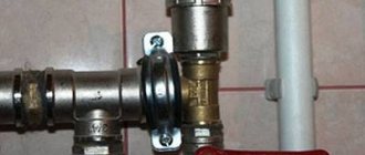
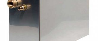
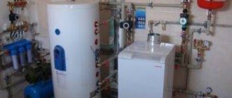
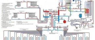
Heating make-up unit Source eurosantehnik.ru
Loss of coolant: reasons
The amount of water in the heating system circuit of a private home may decrease for the following reasons:
As a result of leaks. Water can flow out of the circuit at the joints of pipes when they are depressurized.
When the pressure in the system critically increases and the emergency valve is activated. In this case, part of the coolant is simply discharged from the pipes.
In open systems - due to evaporation from the expansion tank. Nowadays, such elements of the heating system are not completely open. Their design simply provides for contact with the atmosphere. But still, in tanks of this type, water evaporation is usually quite intense.
Due to the activation of air vents. When removing accumulated air bubbles from the circuit, for example, through Mayevsky taps, part of the coolant also comes out (in the form of steam).
Through coarse filters. Such devices require periodic washing. During this procedure, some of the coolant may be lost from the circuit.
How to choose equipment
One of the important points is the selection of a heat source based on power and type of energy carrier used:
- on natural or liquefied gas;
- on solid fuel - wood, coal, pellets;
- on electricity;
- on liquid fuel - diesel fuel, waste oil.
The power of the boiler installation is calculated in the standard way: the heated area of the home is multiplied by 0.1 to convert to kilowatts and by a safety factor of 1.3. That is, for a house of 100 m² you need a heat source with a power of 100 x 0.1 x 1.3 = 13 kW.
For a closed heating system, it does not matter which heat generator you buy, so we will not consider this issue in detail. But you will make your task much easier if you purchase a wall-mounted gas boiler equipped with its own circulation pump and expansion tank, as shown in the photo. For a small house, all that remains is to select pipes and heating devices, which will be discussed further.
Types of pipes
The heating network of a private house can be installed from the following pipes:
- PPR (polypropylene);
- cross-linked polyethylene – PEX, PE-RT;
- metal-plastic;
- metal options: copper, steel and corrugated stainless steel.
For self-installation at low financial costs, it is better to take polymer pipes. To assemble crimp connections from metal-plastic and polyethylene, you do not need special tools, but polypropylene will have to be soldered (a welding machine is rented). Of course, PPR material has no equal in cost, but for reasons of reliability and durability, we recommend using PEX pipelines made of cross-linked polyethylene.
Copper and corrugated stainless steel can also be mounted on compression fittings, but the first has a high price, and the second has significant hydraulic resistance. As for ferrous metal, it is inconvenient in all respects - welding installation and susceptibility to corrosion relegate it to last place. More details about the choice of pipes are described in the next video:
Which radiators are better
The following types of heating devices are currently offered in the retail chain:
- steel panels;
- made from an alloy of aluminum and silicon (silumin);
- the same, but with a frame made of steel pipes, name - bimetallic;
- cast iron batteries are analogues of the Soviet “accordion” MC 140 and retro-style models.
Steel panel radiator
From the point of view of economy, it is more profitable to buy steel batteries, which have an affordable price. Aluminum appliances are more expensive, but give off heat more intensely. These 2 varieties are most in demand for closed heating systems in private houses.
Aluminum heating device
Bimetallic radiators are designed for heating networks with low-quality coolant supplied with pressure drops, which is typical for centralized heating supply of apartment buildings. It makes no sense to buy these expensive products for a country house with autonomous heating.
To select a heating device based on power, make a simple calculation: divide the heat transfer indicated in the passport by 1.5. This way you will find out the real power of the radiator, because the documentation reflects characteristics for certain operating conditions that do not coincide with reality.
Pump and expansion tank
In closed heating systems of private homes, 3 types of household circulation pumps are usually used, developing a pressure of 4, 6 and 8 m of water column (this is a pressure of 0.4, 0.6 and 0.8 bar, respectively). We suggest that you do not delve into complex hydraulic calculations, but select a pumping unit based on the following characteristics:
- For one- and two-story buildings with an area of up to 200 m², a pressure of 4 m is sufficient.
- A cottage with an area of 200-300 m² will need a pump with a pressure of 0.6 Bar (6 m).
- Circulation in the network of a three-story mansion of 400-500 m² will be provided by a unit with a pressure of 8 m of water column.
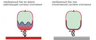
To select the size of the expansion tank, you should calculate the volume of water in the entire closed heating system along with the boiler tank. Considering the fact that when heated from 10 to 90 °C, water expands by approximately 5%, the capacity of the tank should be 1/10 of the total amount of coolant.
Signs of lack of coolant
Water in the heating system circuit can decrease for various reasons. And this happens quite often. If the owners of the house have not yet bothered to install an automatic system for replenishing the heating network, you can determine the lack of coolant by the following signs:
overheating of the supply water supply and cold radiators;
gurgling water in the riser;
frequent starts and stops of the gas boiler burner;
overheating of the solid fuel boiler and activation of the safety valve.
A shortage of coolant in the circuit is especially dangerous if a TT boiler is used as the main heating equipment in the network. If there is not enough water in such a unit, it will boil. After its complete evaporation, a fire will definitely start in the boiler room. Unfortunately, such situations are far from uncommon.
Also, due to a lack of coolant in the heating system, pipes may melt, radiators may fail, etc. Therefore, it is imperative to monitor the pressure in the circuits of heating systems set for private houses (1.5-2 bar).
Filling the system from below
So, let's get back to pumping fluid into the system. We use a container of suitable volume (a 200-liter plastic barrel works well). We lower a pump into it, creating the pressure required for pumping liquid no higher than 1.5 atm (typical value in the range of 1-1.2 atm). Such pressure requires the pump to create a pressure of 15 m (for the submersible “Malysh” it reaches 40 m).
Having filled the barrel with water, we start the pump, monitoring the liquid level, which should be located above its inlet pipe to prevent “airing”. The level drops - add water. Antifreeze should be pumped from a smaller container (bucket) so as not to immerse the submersible pump housing in the liquid (and then wash it) - just immerse the inlet pipe. You will have to add antifreeze frequently, turning off the pump periodically.
Filling the system is carried out with Mayevsky taps open on installed heating radiators with substitute containers for collecting water. When liquid comes out of all air vents, close the taps and continue the injection process.
We control the pressure using a pressure gauge (a boiler gauge will do). When its value exceeds the hydrostatic pressure, equal to the pressure in the liquid column height from the bottom to the top point of the system (a height of 5 m gives a static pressure of 0.5 atm), we continue to fill the system, monitoring with a pressure gauge the moment the pressure reaches the required value.
Pumping antifreeze with the “Malysh” pump.
Having filled the system, turn off the pump, open the air valves (the pressure will inevitably drop), and then pump up the water. We repeat the process several times, displacing air bubbles.
We complete the filling by inspecting the system for leaks. After the pump is turned off, the liquid in the hose connected to the outlet pipe is under pressure. If antifreeze was pumped in, first disconnect the hose from the pump inlet pipe and drain the liquid into a container, being careful not to drench the mechanism body.
Pressure reducing valve
This device is the main element of the design of the automatic replenishment unit for the heating system. It is the pressure reducing valve that is responsible for supplying coolant to the heating circuit of the house when there is a shortage of it from the water pipe. This device is a rather complex structural device, consisting of:
control valve for adjusting pressure;
After inserting the automatic make-up valve into the heating system, the valve is manually adjusted by screwing in to a certain pressure in the circuit. Its rod with a certain force presses the membrane of the device in the outlet hole.
The pressure reducing valve is activated as soon as the pressure in the system drops below the set value. In this case, the membrane will be pressed away from the inlet due to pressure in the water supply network. As a result, water will begin to flow into the heating system circuit. As soon as the pressure in the heating network of a private house reaches the required values again, the membrane will shut off its supply from the water supply.
Selecting a refueling option
Several methods are used to replenish the coolant supply:
- Manual recharge is the cheapest and most versatile option, suitable for all types of wiring.
- Automatic replenishment from the water supply is practiced only in systems operating under pressure.
- To fill a closed network with non-freezing coolant, a manual pressure test pump is also used. The design of an automated circuit with an electric pumping station connected to a container with antifreeze is practiced in industrial boiler houses.
At home, antifreeze is pumped into the heating network using a pressure test pump
Note. If the radiator network and heated floors are filled with antifreeze, simple replenishment is done with a small hand pump. But most often, filtered tap water is used in the heating system, because of the price of non-freezing coolants (especially harmless propylene glycol).
The operating principle of the automatic make-up unit is based on the operation of a pressure reducing valve that responds to a decrease in pressure in the heating network. When it drops below the set value, the valve mechanism opens and releases water from the main line. A pumping station operates in a similar way, pumping antifreeze from a separate tank.
Unit with gearbox (left) and station pumping coolant from the tank (right)
Let us take the liberty of recommending the use of a manual recharge scheme. Causes:
- The unit consists of 2-3 inexpensive elements and will never turn on without the knowledge of the homeowner.
- No matter how reliably and efficiently the heating network is installed, there is a possibility of leakage and valve operation.
- Situation: pipe break, prolonged leakage of coolant in the absence of the owners. A completely autonomous “smart” recharge will flood the entire house, ruining the flooring and causing expensive repairs.
- Imagine an identical situation in an apartment building - a leak from an individual system and the activation of automated replenishment will flood the neighbors below.
- Fine sand will accumulate under the valve seat and the element will lose its seal over time. Under pressure from the water supply of 4-7 bar, spontaneous replenishment will begin. The most harmless scenario is the release of excess coolant through the fuse on the boiler safety group.
To eliminate the consequences of the described troubles, it is better to allocate a little time for personal control over your heating. Having discovered signs of loss of coolant, you will make your own decision - to recharge the system immediately, look for a leak, or make repairs. For a negative example of using such automation, watch our expert’s video:
Check valve
This device is an important element in the design of an automatic heating system replenishment unit. Since when installing a pressure reducing valve, direct contact is formed between two utility networks of the house, there is a possibility that water from the heating pipes will enter the water supply system. To prevent this from happening, a check valve is installed between the pressure reducing device and the junction of the network pipes. In an emergency, this device simply prevents coolant from the heating system from entering the water pipe.
Filling closed heating with a pump
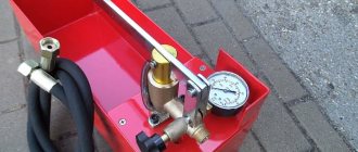
If the circuit is not connected to the water supply, the only option left to fill the heating system is a pressure test pump. This is a small rectangular metal reservoir into which liquid is collected. From the reservoir, the coolant is supplied to the pipes thanks to a pump-action hand pump on which a pressure gauge is installed.
Hand pump for pressure testing.
There is nothing complicated about how to fill a closed heating system. Work algorithm:
- connect the hose from the pump to the circuit;
- pour coolant into the pump reservoir;
- manually pump fluid into the system.
If there is no pipe for draining water from the circuit, then you can connect the pump hose to one of the ends of the battery. To do this, you need to unscrew the plug and put the adapter in its place. Before starting work, be sure to open all air vents so that air can leave the circuit.
When working with thermal insulation in sheets and rolls, you need to use an insulation dowel or nail to fix the material.
Watch the pressure gauge reading carefully. Using such a pump, pressure testing of the heating system is carried out. They can pump up pressure to 10 atmospheres (if you have enough strength). When filling the system, such pressure is not necessary, otherwise the boiler will break.
Water treatment filters
Quite often, devices that purify and soften water in private homes are installed directly at the entrance of the pipe from the well to the house. This allows you to protect the engineering equipment used in the building from scale formation and rust. But in some cases, such complexes are not provided for in private residential buildings.
In such buildings, units for automatic replenishment of the heating system are usually supplemented with water treatment filters. Such devices are also installed in front of the pressure reducing valve.
Plumbing equipment, unlike boilers and circulation pumps, is usually not as sensitive to scale formation. Therefore, various types of softening filters are often not included separately in the hot water and cold water systems. Accordingly, the water in hot water and cold water pipes in private houses can flow quite hard. For a heating system, since boilers and circulation pumps can break down due to scale, such a coolant is not very suitable. It is to clean it from salts and mechanical particles that the replenishment unit is supplemented with softening filters. Typically, in private homes, after the reducer valve for automatically recharging the heating system, the following is installed:
a coarse filter designed to remove small particles from water;
the softener itself.
Final recommendations
When choosing a heating system recharge, be guided by its reliability and ease of use. If you have a small house or apartment, then a simple design is enough. It is recommended to select an actuator with a minimum adhesion coefficient. This material is resistant to the formation of limescale, which means it will last longer.
You can clean the shut-off valve cartridge by following these instructions:
- Isolate make-up equipment.
- Unscrew the control knob at the bottom of the valve.
- Remove the cover by unscrewing the adjusting screw.
- Use pliers to replace the cartridge.
- Put the device back together.
Having installed the recharge, carry out timely repairs of its parts and then the house will always be warm.
Hydraulic accumulator
In some cases, the pressure in the water supply of private houses may be lower than in the heating network. In such a situation, the pressure reducing valve for auto-feeding the heating system, if necessary, will, of course, not work. There is simply not enough pressure in the water supply to press out the membrane.
In this case, a hydraulic accumulator is installed next to the pressure reducing valve. On one side, this element is connected to a water pipe. A top-up shut-off valve is additionally installed at this location. A special small pump is connected to the hydraulic accumulator from below to build up pressure. A shut-off valve with a check valve is installed between such equipment and the storage tank.
As soon as the pump receives a signal from the controlling electromagnetic device about a drop in pressure in the network, it turns on. As a result, the heating system is automatically recharged from the water supply. As soon as the pressure in the circuit reaches the required values, the pump simply turns off.
Autofill device configuration
Before turning on the installation, you need to configure it and indicate the pressure required for operation
If you pay attention to the top of the device, you will find a special screw there, which is designed to adjust the working pressure. Unscrew the screw until it stops and begin to tighten it back slowly, looking at the pressure gauge. When the pressure reaches the level you require, secure it with a lock nut
The lever, which is located at the bottom of the shut-off device, is rarely used, because it is only needed to release fluid into the circuit. This can be done by unscrewing the screw and, accordingly, blocking its output by tightening
When the pressure reaches the level you require, secure it with a lock nut. The lever, which is located at the bottom of the shut-off device, is rarely used, because it is only needed to release fluid into the circuit. This can be done by unscrewing the screw and, accordingly, blocking its output by tightening it.
Take a look around again and make sure that the device is configured correctly and all components are in working order.
Why do you need a bypass?
The automatic recharge unit for heating systems in private houses is in most cases surrounded by a bypass. Experts recommend that you definitely include such an additional pipe in the network. After all, like any other equipment, the recharge unit may require repairs. If any of its elements break down, water can be supplied to the heating network circuit through a bypass.
Such a bypass pipe in the make-up system can also perform another important function. It is very convenient to carry out circular washing of the filters included in the design of the unit through the bypass.
Differences between closed loop recharge
Closed systems are characterized by internal high pressure, so manually adjusting the coolant level is difficult. To solve the problem, automatic equipment is installed. It independently monitors losses and replenishes them as needed. It is important that such a device has filters built into the gearbox, check valve and gate valve. Closed circuits should always be equipped with a pressure gauge to visually monitor the pressure inside.
Choosing an installation location
It is not allowed to cut into the structure. make-up anywhere in the heating circuit. The installation site standards are described in SNiP, here are some of them:
- Make-up equipment is installed in a place with minimal pressure in the heating system. In a closed circuit, the installation is mounted near the pumping unit.
- To ensure that the coolant does not get into the cold water supply, additional shut-off valves are installed.
- If the circulation pump begins to increase the pressure in the heating system beyond what the make-up provides, an additional pump will be needed in front of the equipment that makes up for losses in the circuit.
Where is the best place to install
The “zero” point of any heating network is considered to be the point of insertion into the circuit of the expansion tank. This is where, theoretically, the valve for automatically recharging the heating system should be connected. However, in practice, installing such equipment in this location may, unfortunately, not be the most successful option. The fact is that expansion tanks in heating systems are often mounted directly next to the boilers.
In this case, the incoming return water will mix with water from the water supply and enter the boiler too cold. This can lead to malfunctions of the heating unit or even to its breakdown. Therefore, the automatic replenishment unit is usually simply carried a little further than the expansion tank and cut into the return line.
It is also possible to connect such equipment to a hot water supply. In this case, the unit, of course, can be placed next to the expansion tank and boiler.
Experts do not recommend installing make-up equipment at the supply in any case. This can damage valves and filters. After all, the water in the supply pipe flows very hot.
Automatic make-up equipment is installed in the heating system, usually using a 13-inch pipe section. Installation of the unit in most cases is carried out in the following order:
the assembly is prepared by packing all threaded elements;
an American is mounted on one side of the unit, and an end coupling on the other;
assembly taps are soldered;
the assembled unit is connected at a selected point in the system.
The answer to the question of how to install automatic recharge of the heating system in a private house is thus relatively simple.
After installation, among other things, the pressure relief valve is adjusted. In order to set the pressure required for the system, the valve of this device is first completely unscrewed. Then it slowly closes back until the desired parameters are reached. At the final stage, the valve is securely secured with a locknut.
Tips for installation and configuration
The normal operation of the machine for recharging the heating system largely depends on the installed elements and its location on the diagram. It must be repeated once again that the installation of the unit should only be carried out on the heating return pipe. Otherwise, false alarms of the system are possible, which is incorrect.
Bypass
Heating make-up installation options
In the automatic recharge of any heating system, breakdowns of individual components are possible. There is a possibility of a decrease in coolant or the impossibility of adding it to the pipeline in any other way. Therefore, the unit should be installed on bypass.
With this recharge scheme, in the event of a breakdown or the need for preventive maintenance, you can manually supplement the heating system
However, this must be done very carefully, since there is a high probability of exceeding the critical volume of water in pipes and radiators, which will lead to a sharp increase in pressure
Procedure:
- We close the shut-off valves on the heating system make-up valve line.
- We open the shut-off valves on the bypass, ensuring the flow of water.
- We monitor the value on a pressure gauge, which is located not on the feed line of a closed system, but after it directly in front of the pump or boiler.
- As soon as the pressure value reaches the desired level (from 1.5 to 3 atm.), we close the taps on the bypass.
Filtration
Filtration water purification system
Since the above schemes provide for the addition of tap water, it is necessary to provide for the installation of a filter system. By default, almost all gearboxes for feeding the heating system are equipped with mesh elements. However, they are designed only to retain foreign impurities of a large fraction. It is best to install a full-fledged coolant pre-cleaning system.
In this case, you can purchase a household kit for drinking water purification, as it performs the required functions. In this case, the operation of the automatic make-up unit for the heating system will be much more efficient:
- The likelihood of limescale deposits on pipes and radiators will decrease;
- The percentage of air in the liquid will decrease, which will have a beneficial effect on the absence of corrosion processes;
- The frequency of mandatory flushing of the heating system will increase.
In the video you can see an interesting heating replenishment scheme in the presence of an indirect heating boiler:
Manufacturers
To prevent home owners from having problems with their heating system in the future, they must, of course, choose make-up equipment as carefully as possible. When purchasing all the necessary elements, among other things, you should pay attention to the manufacturer’s brand.
For example, the automatic recharge units of the Valtec heating system have received very good reviews from consumers. Pressure reducers from this manufacturer are initially supplemented with check valves, a pressure gauge and a filter. The unit of this brand is made of brass. The company makes the gearbox and check valve springs from stainless steel. Valtec gearboxes are designed for a maximum operating coolant temperature of up to 130 °C and a pressure of 16 bar.
The Watts automatic heating system also received good reviews from consumers. This oldest European manufacturer supplies the market with very high-quality and durable recharge units. Valves from this manufacturer are also made of brass and are equipped with a coarse filter. Some models also have pressure gauges.
Another popular brand of make-up equipment in our country is Emmeti. These auto-feeding valves for heating systems are produced by the company of the same name, which is quite new, but has already proven itself to be the best. All products supplied to the market by this manufacturer, including pressure reducing valves, are ISO 9001 certified.
Essential elements
Like any equipment, make-up consists of several parts. Let's look at each detail separately.
Actuating mechanism
With manual control, one valve is installed through which water is supplied or shut off. Automatic equipment may contain various types of remote control devices. The most popular option is a pressure reducing valve. It consists of three parts: a shut-off and check valve, as well as a pressure reducer. At the same time, it is installed both in mechanical systems and equipped with electrical control sensors.
A lower pressure threshold is set in the actuator. When the pressure gauge detects losses, the membrane releases the spring, which acts on the operating rod, after which the valve opening opens. When the pressure returns to normal, the membrane again presses on the spring and the rod snaps into place, closing the passage with a cone.
You can set the pressure threshold at which the supply of working fluid will begin using a screw attached to the top of the actuator. Having installed it in a certain position, the position is fixed with a lock nut. In order not to make a mistake with the adjustable pressure, the device has a pressure gauge.
Check valve
The working fluid from the heating system should not be mixed with drinking tap water. This will lead to negative consequences:
- Will make water unfit for human consumption due to the development of bacteria.
- Since heating pipes gradually deteriorate inside, corrosion can enter the water, which is harmful to health.
- Decrease in boiler efficiency due to pressure loss and temperature drop.
Make-up in an open heating system
In heating networks of private houses with forced coolant flow, therefore, valves are used for make-up, supplying water to the circuit automatically. In open systems of small residential buildings or dachas, a slightly different, much simpler coolant addition scheme is usually used. Automatic recharging of the heating system in this case will most likely be superfluous.
Expansion tanks in networks with natural coolant flow are usually mounted in the attic. In order to be able to control the amount of water in the circuit in such systems, in addition to the return and supply, two more pipes are connected to them. One of them is called the control one and cuts into the tank below. The second (overflow pipe) is connected to the expansion tank at the top. Next, the pipes are extended, for example, to the kitchen.
Checking whether there is a sufficient amount of water in the heating system circuit when using such a design is quite simple. If the coolant does not flow from the tap embedded in the control pipe of the tank when it is opened, then there is not enough coolant in the system. In this case, before adding liquid to the circuit, open the tap on the overflow pipe. As soon as the system is filled to the required parameters, water will begin to flow from it.
Installation features
The direction of the water must coincide with the direction of the arrow on the body of the device.
The valve is placed on the pipe so that the direction of the liquid coincides with the direction of the arrow. The filter plug is directed downward, and the adjustment screw must be accessible for use. The pressure gauge dial rotates to make it easy to read the values.
The winding material is used rationally so that excess does not fall into the lumen of the gearbox. Boiler feed in the form of a valve should not depend on main loads (compression, torsion, bending, vibration). For this purpose, additional supports or compensators are installed.
The mismatch between the axes of the pipelines should not be more than 3 mm for a length of 1 m. For longer lengths, 1 mm is added for each linear meter. The make-up circuit is connected to the pipeline near the expansion tank.
Networks with antifreeze
How to automatically recharge a heating system with water is thus clear. To do this, you need to buy a pressure reducing valve and embed it into the circuit, adding a check valve and filters.
In most cases, water is used as a coolant in heating networks of private houses. But sometimes heated antifreeze can flow along the lines of such engineering systems. This type of coolant is most often used at dachas when they are visited irregularly in winter.
Antifreeze, unlike water, does not harden at subzero temperatures. And therefore, when using it, there is no damage to the equipment. After all, water expands when it freezes and can rupture pipes and boiler structures.
Of course, you cannot connect a pressure reducing valve when using antifreeze in the circuit. Diluting such a coolant with water will lead to a change in its qualities and stop the heating system. When using antifreeze, accordingly, other replenishment systems must be used.
In this case, if necessary, an additional amount of coolant is usually poured into the circuit manually - from canisters, bottles, etc. This is done through a special drain valve. In such systems, only pressure control in the circuit can be carried out automatically. For this purpose, pressure gauges are used in antifreeze networks.
Replacing water with antifreeze
If the system has already used water, and you want to switch to antifreeze, then two circumstances should be taken into account.
Secondly
. It is never possible to completely remove water from the heating system. Some of the water remains. If you simply pour prepared diluted antifreeze, its concentration will be insufficient for reliable protection against freezing. Thus, a concentrate must be used. I usually mix concentrate with diluted antifreeze in a 1:1 ratio. After filling the system, you need to start the circulation pump (for a system with forced circulation) or turn on the boiler (for a system with natural circulation) so that the coolant is thoroughly mixed. Then you need to pour out some coolant and measure its density. There is a device for measuring density that is sold in most car dealerships. This device is used to prepare a car for winter (checking the properties of antifreeze in the engine cooling system), but it is also perfect for our purposes. If the device shows a freezing temperature lower than necessary, for example -50 degrees, it’s okay, but if the temperature is higher than we need, then we will have to drain part of the coolant and replace it with concentrate. The drained coolant must be disposed of carefully; it is poisonous and should not be poured into septic tanks or ditches.
I would also like to draw your attention to the fact that different antifreezes may be incompatible with each other. There is an opinion that red composition should not be mixed with a composition of another color. This is true, but in fact there are other undesirable combinations
Supplements from different brands may react with each other or simply reduce each other's effectiveness. Unfortunately, manufacturers do not indicate what other antifreezes their product can be mixed with. My advice is to pick one brand and stick with it. If you still need to mix, then mix liquids of the same color and before pouring, pour a little coolant from the heating system, mix it in a jar with a new composition and see if a sediment forms, if the liquid becomes cloudy, or if it loses its homogeneity
This is true, but in fact there are other undesirable combinations. Supplements from different brands may react with each other or simply reduce each other's effectiveness. Unfortunately, manufacturers do not indicate what other antifreezes their product can be mixed with. My advice is to pick one brand and stick with it. If you still need to mix, then mix liquids of the same color and before pouring, pour out a little coolant from the heating system, mix it in a jar with a new composition and see if a sediment forms, if the liquid becomes cloudy, or loses its homogeneity.
Automatic make-up of the heating system - diagram of the unit and make-up valve
When air vents in a heating system are activated due to air escaping, the volume of coolant certainly decreases. Also, the number of liters of coolant becomes smaller due to the cleaning of filters from various contaminants.
In addition, changes in temperature conditions, which depend on the weather outside the window, result in an increase or decrease in heat loss from the building. As a result, the operating mode of the heating unit’s burner periodically changes. This element of the boiler either intensively heats the water or operates in economical mode.
The cyclical operation of the heating system often leads to sudden changes in pressure in different components of the structure and the activation of safety valves. As a result, the collet connections may become loose and the coolant will begin to leak out. In order to prevent emergency situations in the heating system, it is necessary to maintain a constant volume of coolant liquid and pressure in accordance with the recommendations of the boiler manufacturers (according to the technical data sheet). This can be done by an automatic replenishment unit for the heating system.
The main part in it is the pressure reducing valve shown in the photo. The heating system make-up valve is equipped with a special membrane under coolant pressure. Thanks to the tension of the spring, the required pressure for the liquid is established, at which the membrane moves to the upper position and ultimately compresses the spring. The use of a valve makes recharging a closed heating system faster, easier and safer.
After the pressure in the heating system drops (behind the valve), the coolant no longer acts on the membrane, and the spring pushes the valve stem down, opening a gap in the seat in this element. Water from the plumbing structure begins to flow through the opened hole into the pipeline of the heating system. After reaching the nominal pressure, the membrane bends upward and closes the valve seat.
It should be noted that the pressure relief valve for automatically recharging the heating system is often open. It responds to every operation of automatic air vents. Since air is removed from the heating structure on a regular basis, the automatic replenishment of the heating system operates quite often. To prevent dirty water from entering the water supply system, a check valve is installed behind the pressure reducing valve. This element is either built into the pressure reducing valve body or used as a separate part.
Modern environmental requirements stipulate that a flow breaker or check valve should also be located in front of the pressure reducing valve. A part such as a flow breaker performs the function of a check valve, but is an improved product consisting of two check valves and a drain pipe located between them.
According to European regulations, a flow breaker must be installed. The fact is that hot water entering the water supply network from the heating structure provokes the proliferation of various bacteria in the pipes, settling on the inner surfaces of the walls.
In order to soften the water and prevent the appearance of scale, as provided for in the heating system recharge scheme, a water treatment filter is installed in front of the pressure reducing valve. Sometimes it is replaced with ordinary mesh filters or mud filters. Mesh filters that do not have a transparent flask can be equipped with pressure gauges, which allows you to monitor the pressure of the coolant in front of them and behind these products (read: “Filter for a heating system - principle of operation and installation”). According to the pressure drop indicators, the degree of filter contamination is determined.
It is recommended to bypass the heating system make-up unit using a bypass and shut-off (ball) valves. If suddenly this unit or one of its elements fails, then replenishment is carried out through a bypass (for more details: “What is a bypass in a heating system and why is it needed - types, installation rules”). The most convenient place to connect such a unit is the point where the expansion tank is located, which serves as a “zero” reference point in the design.
The fact is that in this place the heating system is fed - the calculation confirms this - the pressure reducing valve functions most accurately. But in this case, a problem arises because this location of the make-up unit is too close to the heating boiler. As a result, water from the water supply mixes with the return water, cools the liquid and it enters the unit too cold, which adversely affects the operation of the device. For this reason, if the replenishment of the heating system of a private house should be located close to the heating unit, it is recommended to install the unit in the hot water supply system.
If the water supply in a country house is irregular, a storage hydraulic accumulator is installed in front of the recharge unit, which comes in two types. This is either a feeding tank for the heating system in the attic, or a membrane tank similar to an expansion tank. When the water pressure in the water supply is less than in the heating system, the pressure reducing valve will not function, then it is necessary to install a hydraulic accumulator.
The heating make-up unit is connected directly to the household water supply battery.
Recharge calculation
The calculation of the required volume of added water is carried out in accordance with SNiP 41-02-2003 “Heating networks”.
In closed heating circuits, a coefficient of 0.075 is used to the total volume of energy in the networks and pipelines connected to them.
A multiplier of 0.05 is applied to the volume to calculate the make-up of areas that are more than 5 km from the boiler house, in open and closed systems.
In open pipelines, a coefficient of 0.12 is taken to the average liquid flow rate for hot water supply and the actual volume of energy carrier in the pipes is added with a multiplier of 0.075.
Feeding the boiler heating system from the water supply: what is it?
Operation of the piping leads to a decrease in the amount of coolant in it. The free space fills with air, creating traffic jams. As a result, the equipment overheats , which causes breakdowns.
Water is lost in the following situations:
- In an open circuit, the liquid evaporates in the expansion tank.
- The air vent also removes water vapor.
- When the overheating protection mechanism is triggered, the coolant is discharged.
- There are invisible cracks in the harness.
- Pipes become covered with scale or rust.
To avoid problems, use heating recharge from the water supply. In most cases, it works autonomously, measuring the current volume of water and replenishing the deficiency. This restores the system's standard pressure. For this, cold water supply or a special liquid stored in a storage tank is used.
How to do it: feed or return diagram
The process is performed in one of two ways:
- Manual is done in small systems, since pressure changes in them are smaller. The latter are determined with a pressure gauge. Having detected a deviation from the norm, open the make-up valve and wait for the value to be restored.
- The automatic installation independently processes the data and takes measures to resolve problems.
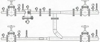
Photo 1. Scheme of automatic installation of a heating system make-up station, data is processed independently.
The difference is that there is no need to monitor the readings , but due to the constant operation of the device, energy consumption increases.
Important! Recharge is not required constantly, but the equipment does not need to be idle. Using the device, you can fill an empty pipe with coolant , carry out pressure testing or flush the pipes.
Finally, about the safe addition of coolant
When filling water or partial replenishment, follow our recommendations:
- Replenish the heated system slowly by opening the valve a quarter of the lever stroke. In this way, it will be possible to avoid the formation of air locks and protect the boiler heat exchanger from temperature shock.
- Refill from scratch with the heat generator not working and the circulation pump turned off.
- Check the pressure in the expansion tank and go through all the radiators, opening the Mayevsky valves to release air.
- If your boiler is equipped with modern electronics, be sure to study the instructions regarding make-up. Often it is necessary to activate a special service mode in the unit.
- Excess pressure is easily released through the nearest air vent.
The complex system make-up module can be connected to a hydraulic separator and a comb
Reference. Cast iron heat exchangers easily crack from sudden temperature changes, and steel fireboxes become covered from the inside with condensation. The latter mixes with soot and forms a dense coating.
Injecting antifreeze with a hand pump does not have any pitfalls. Pressure testing units are equipped with their own pressure gauge, which allows you to monitor the current pressure at the insertion point.
Types of make-up valve control
There are two types of heating system make-up valve:
- mechanical;
- auto.
A mechanically controlled device can be mounted in compact heating systems due to the fact that there the increased pressure is influenced by the membranes of the tanks. In this case, you can reduce the volume of liquid yourself by simply opening the water supply tap.
However, to carry out these works at the right time requires a little experience. Due to the fact that it is necessary to regularly adjust the pressure values inside the heating system and the volume of liquid. If there is too much coolant, then emergency situations are likely to occur. The automatic type valve must be installed in large heating systems where there are many circuits.
In modern models of boiler equipment, an automatic valve (also called a pressure reducing valve) is included in the standard kit. To be more precise, this device is part of the automation. It is possible to install a feed reducer separately only if the entire circuit is dependent on electrical energy.
Where to put the circulation pump?
Most often, the circulation pump is installed on the return side, and not on the supply side. It is believed that there is a lower risk of rapid wear and tear of the device, since the coolant has already cooled down. But for modern pumps this is not necessary, since they have so-called water-lubricated bearings. They are already designed specifically for such operating conditions.
This means that it is possible to install a circulation pump on the supply side, especially since here the hydrostatic pressure of the system is lower. The installation location of the device conventionally divides the system into two parts: the discharge area and the suction area. A pump installed on the supply, immediately after the expansion tank, will pump water out of the storage tank and pump it into the system.
The circulation pump in the heating system divides the circuit into two parts: the injection area into which the coolant flows, and the vacuum area from which it is pumped out
If the pump is installed on the return line in front of the expansion tank, then it will pump water into the tank, pumping it out of the system. Understanding this point will help take into account the characteristics of hydraulic pressure at various points in the system. When the pump is running, the dynamic pressure in a system with a constant amount of coolant remains constant.
It is important not only to choose the optimal location for installing pumping equipment, but also to install it correctly. We recommend that you familiarize yourself with the nuances of installing a circulation pump
The expansion tank creates so-called static pressure. Relative to this indicator, an increased hydraulic pressure is created in the discharge area of the heating system, and a reduced one is created in the vacuum area.
The vacuum can be so strong that it will reach the level of atmospheric pressure or even be lower, and this creates conditions for air to enter the system from the surrounding space.
In the area of increased pressure, air can, on the contrary, be pushed out of the system, and sometimes boiling of the coolant is observed. All this can lead to incorrect operation of heating equipment. To avoid such problems, ensure excess pressure in the suction area.
To do this, you can use one of the following solutions:
- raise the expansion tank to a height of at least 80 cm from the level of the heating pipes;
- place the drive at the highest point of the system;
- disconnect the storage pipe from the supply and transfer it to the return after the pump;
- install the pump not on the return, but on the supply.
It is not always possible to raise the expansion tank to a sufficient height. It is usually placed in the attic if there is the necessary space
It is important to adhere to the rules for installing the drive to ensure its trouble-free operation.
We provided detailed recommendations for installing and connecting an expansion tank in our other article.
If the attic is not heated, the storage tank will have to be insulated. It is quite difficult to move the tank to the highest point of a forced circulation system if it was previously created as a natural one.
Part of the pipeline will have to be redone so that the slope of the pipes is directed towards the boiler. In natural systems, the slope is usually made towards the boiler.
An expansion tank installed indoors does not need additional protection, but if it is installed in an unheated attic, care should be taken to insulate this device
Changing the position of the tank pipe from supply to return is usually not difficult to perform. And it’s just as easy to implement the last option: install a circulation pump into the system on the supply line behind the expansion tank.
In such a situation, it is recommended to choose the most reliable pump model that can withstand contact with hot coolant for a long time.
