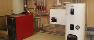
In modern conditions, people are increasingly thinking about the rational use of resources. Electricity, water, materials. The world has come to saving all this quite a long time ago and everyone understands how to do it. But the main amount in the payment bills is heating, and not everyone understands how to reduce the cost on this item.
What is thermal engineering calculation?
Thermal engineering calculations are performed in order to select the thickness and material of the enclosing structures and bring the building into compliance with thermal protection standards. The main regulatory document regulating the ability of a structure to resist heat transfer is SNiP 23-02-2003 “Thermal protection of buildings”.
The main indicator of the enclosing surface from the point of view of thermal protection was the reduced heat transfer resistance. This is a value that takes into account the thermal protection characteristics of all layers of the structure, taking into account cold bridges.
A detailed and competent thermal calculation is quite labor-intensive. When constructing private houses, owners try to take into account the strength characteristics of materials, often forgetting about heat conservation. This can lead to quite disastrous consequences.
Calculation of heat loss by area of premises
The first method of calculating the heat load of a heating system is used to broadly determine the power of the heating system of the entire house and a general understanding of the number and type of radiators, as well as the power of boiler equipment. Since the method does not take into account the region of construction (calculated outside temperature in winter), the amount of heat loss through foundations, roofs or non-standard glazing, the amount of heat loss calculated by the aggregated method based on the area of the room may be either more or less than the actual values.
Sources of building heat loss
And when using modern thermal insulation materials, the power of boiler equipment can be determined with a large margin. Thus, when installing heating systems, there will be a large waste of materials and more expensive equipment will be purchased. Maintaining a comfortable temperature in the premises will be possible only if modern automation is installed, which will prevent overheating of the premises above comfortable temperatures.
In the worst case, the power of the heating system may be underestimated and the house will not be warmed up on the coldest days.
Nevertheless, this method of determining the power of heating systems is used quite often. You just need to understand in what cases such enlarged calculations are close to reality.
So, the formula for an aggregated determination of the amount of heat loss is as follows:
Q = S * 100 W (150 W), Q is the required amount of heat needed to heat the entire room, W S is the heated area of the room, m?
The value of 100-150 Watts is a specific indicator of the amount of thermal energy required to heat 1 m². When using the first method for the enlarged method of calculating thermal power, you should focus on the following recommendations:
- In the case when the design room made of external enclosing structures has one window and one external wall, and the ceiling height is less than three meters, then 100 W of thermal energy falls per 1 m2 of heated area.
- When calculating a corner room with two window structures or balcony blocks, or a room with a height of more than three meters, the range of specific thermal energy per 1 m2 is from 120 to 150 W.
- If in the future it is planned to install a heating device under a window in a niche or decorate it with protective screens, the surface of the radiators and, consequently, their power must be increased by 20-30%. This is due to the fact that the thermal power of the radiators will be partially spent on heating additional structures.
Why is the calculation performed?
Before starting construction, the customer can choose whether he will take into account thermal characteristics or ensure only the strength and stability of structures.
Costs for insulation will definitely increase the cost of building construction, but will reduce the costs of further operation. Individual houses are built to last for decades, and perhaps they will serve future generations. During this time, the cost of effective insulation will pay for itself several times over.
What the owner receives if the calculations are performed correctly:
- Savings on space heating. Heat losses of the building are reduced, and accordingly, the number of radiator sections in a classic heating system and the power of the underfloor heating system will decrease. Depending on the heating method, the owner’s costs for electricity, gas or hot water become less;
- Saving on repairs. With proper insulation, a comfortable microclimate is created in the room, condensation does not form on the walls, and microorganisms dangerous to humans do not appear. The presence of fungus or mold on the surface requires repairs, and simple cosmetic repairs will not bring any results and the problem will arise again;
- Safety for residents. Here, as in the previous paragraph, we are talking about dampness, mold and mildew, which can cause various diseases in people constantly staying indoors;
- Respect for the environment. There is a shortage of resources on the planet, so reducing the consumption of electricity or blue fuel has a beneficial effect on the environmental situation.
Coefficients for calculating building heat losses
It is important not only to know the necessary formula required to calculate the required heat energy for heating a building, but also to apply the following coefficients, which allow you to take into account absolutely all the factors influencing such calculations:
- K1 is the type of windows with which a specific room is equipped;
- K2 are indicators of thermal insulation of the walls of the structure;
- K3 – indicator of the ratio of the area of window openings and floors;
- K4 – the lowest temperature outside the house;
- K5 – the number of external walls present in the structure;
- K6 – number of floors in the building;
- K7 – room height parameter.
If we talk about heat loss through windows, it is important to remember the coefficients for such calculations, which are:
- for windows with standard glazing this parameter is 1.27;
- for double-glazed windows – 1;
- for three-chamber double-glazed windows – 0.85.
Do not forget that the increase in the volume of windows relative to the floors in the house is directly proportional to the increase in heat loss in the building. So, the ratio of window areas and floors in a home will be:
- for 10% – 0.8;
- for 10 – 19% – 0.9;
- for 20% – 1;
- for 21 – 29% – 1.1;
- for 30% – 1.2;
- for 31 – 39% – 1.3;
- for 40% – 1.4;
- for 50% – 1.5.
When calculating the consumption of the required amount of heat energy, it is also important to remember that the material from which the walls of the structure are made also has its own coefficients:
- for blocks or concrete panels - from 1.25 to 1.5;
- for log walls or walls made of timber - 1.25;
- for brickwork with a thickness of 1.5 bricks - 1.5;
- for 2.5 brickwork – 1.1;
- for foam concrete blocks – 1.
It is also worth considering the fact that if temperatures outside the house are low, then heat losses become more significant, for example:
- if the temperature reaches -10°C, the coefficient will be 0.7;
- if this parameter is below -10°C, then the coefficient should be 0.8;
- if the temperature is -15°C, then the figure will be 0.9;
- at frost temperatures of -20°C the coefficient should be 1;
- coefficient value at -25°C – 1.2;
- if the temperature drops to -30°C, the coefficient should be equal to 1.2;
- if the thermometer outside reaches -35°C, then the coefficient should be 1.3.
In addition, when calculating the amount of heat required to heat a house, it is important to directly take into account the area of the room, which is displayed as PC, as well as the specific value that constitutes heat loss - this is UDtp.
So, you can calculate the amount of possible heat loss from a particular room using the following formula: Tp = UDtp * Pl * K1 * K2 * K3 * K4 * K5 * K6 * K7. The UDTP parameter in this case should be equal to 100 W/m².
Regulatory documents for performing calculations
The given resistance and its compliance with the standardized value is the main goal of the calculation. But to carry it out you will need to know the thermal conductivity of the materials of the wall, roof or ceiling. Thermal conductivity is a value characterizing the ability of a product to conduct heat through itself. The lower it is, the better.
When performing calculations, heating engineers rely on the following documents:
- SP 50.13330.2012 “Thermal protection of buildings”. The document was reissued based on SNiP 02/23/2003. Basic standard for calculation [1];
- SP 131.13330.2012 “Building climatology”. New edition of SNiP 23-01-99*. This document allows you to determine the climatic conditions of the locality in which the object is located [2];
- SP 23-101-2004 “Design of thermal protection of buildings” covers the topic in more detail than the first document in the list [3];
- GOST 30494-96 (replaced by GOST 30494-2011 since 2011) “Residential and public buildings” [4];
- A manual for students of construction universities E.G. Malyavin “Heat loss of a building. Reference manual" [5].
* - further in the text I will refer to regulatory documents and in order not to completely spell out their name, I will indicate only the number, for example [1].
Thermal engineering calculations are not complicated. It can be performed by a person without special education using a template. The main thing is to approach the issue very carefully.
How to do thermal engineering calculations of the walls of a house - basic parameters
Before proceeding with direct heat calculations, you need to collect detailed information about the construction. The report will include answers to the following points:
- The purpose of the building is residential, industrial or public premises, a specific purpose.
- The geographic latitude of the area where the facility is or will be located.
- Climatic features of the area.
- The direction of the walls is to the cardinal points.
- Dimensions of entrance structures and window frames - their height, width, permeability, type of windows - wooden, plastic, etc.
- Power of heating equipment, layout of pipes, batteries.
- The average number of residents or visitors, workers, if these are industrial premises that are located inside the walls at the same time.
- Building materials from which floors, ceilings and any other elements are made.
- The presence or absence of hot water supply, the type of system that is responsible for this.
- Features of ventilation, both natural (windows) and artificial - ventilation shafts, air conditioning.
- The configuration of the entire building - the number of floors, the total and individual area of the premises, the location of the rooms.
Once this data has been collected, the engineer can begin calculations.
We offer you three methods that are most often used by specialists. You can also use a combined method, when facts are taken from all three possibilities.
An example of calculating a three-layer wall without an air gap
Let's take a closer look at an example of a thermal engineering calculation. First you need to decide on the initial data. As a rule, you choose the materials for wall construction yourself. We will calculate the thickness of the insulating layer based on the wall materials.
Initial data
The data is individual for each construction project and depends on the location of the object.
Climate and microclimate
- Construction area: Vologda.
- Purpose of the object: residential.
- Relative air humidity for a room with normal humidity conditions is 55% ([1] clause 4.3. table 1).
- The temperature inside residential premises tint is set by regulatory documents ([4] table 1) and is equal to 20 degrees Celsius.”
text — estimated outside air temperature. It is set by the temperature of the coldest five days of the year. The value can be found in [2], table 1, column 5. For a given area, the value is -32ᵒС.
zht = 231 days – the number of days in the period when additional heating of the room is necessary, that is, the average daily temperature outside is less than 8ᵒC. The value is looked for in the same table as the previous one, but in column 11.
tht = -4.1ᵒС – average outside air temperature during the heating period. The value is shown in column 12.
Wall materials
All layers should be taken into account (even the plaster layer, if there is one). This will allow you to calculate the design most accurately.
In this version, we consider a wall consisting of the following materials:
- layer of plaster, 2 centimeters;
- the inner verst is made of ordinary solid ceramic brick, 38 centimeters thick;
- a layer of Rockwool mineral wool insulation, the thickness of which is selected by calculation;
- the outer verst is made of facing ceramic brick, 12 centimeters thick.
Thermal conductivity of adopted materials
All properties of materials must be presented in the manufacturer’s passport. Many companies provide complete information about their products on their websites. For convenience, the characteristics of the selected materials are summarized in a table.
| No. | Material | Layer thickness, δ, mm | Thermal conductivity, λ, W/(m*ᵒС) | Density, ρ, kg/m3 |
| 1 | Complex plaster solution | 20 | 0,87 | 1700 |
| 2 | Masonry of ordinary ceramic solid bricks | 380 | 0,48 | 1600 |
| 3 | Rockwool mineral wool slabs | Unknown | 0,038 | 90 |
| 4 | Solid face ceramic brick masonry | 120 | 0,48 | 1600 |
Calculation of insulation thickness for a wall
Energy saving condition
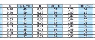
Calculation of the heating period degree-day value (HSDP) is carried out using the formula:
Dd = (tint - tht) zht.
All letter designations presented in the formula are deciphered in the source data.
Dd = (20-(-4.1)) *231=5567.1 ᵒС*day.
We find the standard heat transfer resistance using the formula:
Rreq=a*Dd+b.
Coefficients a and b are taken according to Table 4, column 3 [4].
For the initial data a=0.00045, b=1.9.
Rreq = 0.00045*5567.1+1.9=3.348 m2*ᵒС/W.
Calculation of thermal protection standards based on sanitation conditions
This indicator is not calculated for residential buildings and is given as an example. The calculation is carried out when there is an excess of sensible heat exceeding 23 W/m3, or the building is used in spring and autumn. Also, calculations are necessary at a design temperature of less than 12ᵒC indoors. Use formula 3 [1]:
Coefficient n is taken according to Table 6 of the SP “Thermal Protection of Buildings”, αint according to Table 7, Δtn according to the fifth table.
Rreq = 1*(20+31)4*8.7 = 1.47 m2*ᵒC/W.
Of the two values obtained in the first and second paragraphs, the largest is selected, and further calculations are carried out based on it. In this case, Rreq = 3.348 m2*ᵒС/W.
Determining the thickness of insulation
The heat transfer resistance for each layer is obtained by the formula:
Ri = δi/λi,
where δ is the thickness of the layer, λ is its thermal conductivity.
a) plaster R pcs = 0.02/0.87 = 0.023 m2*ᵒC/W; b) ordinary brick R row.brick. = 0.38/0.48 = 0.79 m2*ᵒC/W; c) facing brick Rth = 0.12/0.48 = 0.25 m2*ᵒС/W.
The minimum heat transfer resistance of the entire structure is determined by the formula ([5], formula 5.6):
Rint = 1/αint = 1/8.7 = 0.115 m2*ᵒС/W; Rext = 1/αext = 1/23 = 0.043 m2*ᵒС/W; ∑Ri = 0.023+0.79+0.25 = 1.063 m2*ᵒС/W, that is, the sum of the numbers obtained in point 3;
Rtro = Rreq.
R_tr^ut = 3.348 – (0.115+0.043+1.063) = 2.127 m2*ᵒC/W.
The thickness of the insulation is determined by the formula ([5] formula 5.7):
δ_tr^ut = 0.038*2.127 = 0.081 m.
The found value is minimal. The insulation layer is no less than this value. In this calculation, we assume the final thickness of the mineral wool insulation is 10 centimeters, so that we do not have to cut the purchased material.
To calculate the heat losses of a building, which are performed for the design of heating systems, it is necessary to find the actual value of heat transfer resistance with the found insulation thickness.
Ro = Rint+Rext+∑Ri = 1/8.7 + 1/23 + 0.023 + 0.79 + 0.1/0.038 + 0.25 = 3.85 m2*ᵒС/W > 3.348 m2*ᵒС/W.
The condition is met.
Formulas for making calculations
Heat loss from a house can be divided into two main parts: losses through the building envelope and losses caused by the operation of the ventilation system. In addition, heat is lost when warm water is discharged into the sewer system.
Losses through building envelopes
For the materials from which the enclosing structures are constructed, it is necessary to find the value of the thermal conductivity index Kt (W/m x degree). They are in the relevant reference books.
Now, knowing the thickness of the layers, using the formula: R = S/Kt , calculate the thermal resistance of each unit. If the structure is multilayer, all obtained values are added together.
The easiest way to determine the size of heat losses is by adding up the thermal flows through the enclosing structures that actually form this building
Guided by this methodology, they take into account the fact that the materials that make up the structure have a different structure. It is also taken into account that the heat flow passing through them has different specifics.
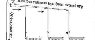
For each individual structure, heat loss is determined by the formula:
Q = (A / R) x dT
Here:
- A is the area in m².
- R is the resistance of the structure to heat transfer.
- dT is the temperature difference between outside and inside. It needs to be determined for the coldest 5-day period.
Performing the calculation in this way, you can get the result only for the coldest five-day period. The total heat loss for the entire cold season is determined by taking into account the dT parameter, taking into account not the lowest temperature, but the average one.
The extent to which heat is absorbed, as well as heat transfer, depends on the humidity of the climate in the region. For this reason, humidity maps are used in calculations.
Next, the amount of energy required to compensate for heat loss lost both through the building envelope and through ventilation is calculated. It is denoted by the symbol W.
There is a formula for this:
W = ((Q + Qв) x 24 x N)/1000
In it, N is the duration of the heating period in days.
Disadvantages of area calculation
Calculation based on the area indicator is not very accurate. Here, such parameters as climate, temperature indicators, both minimum and maximum, and humidity are not taken into account. Due to ignoring many important points, the calculation has significant errors.
Often trying to cover them, the project includes a “reserve”.
If, nevertheless, this method is chosen for calculation, the following nuances must be taken into account:
- If the height of vertical fences is up to three meters and there are no more than two openings on one surface, it is better to multiply the result by 100 W.
- If the project includes a balcony, two windows or a loggia, multiply by an average of 125 W.
- When the premises are industrial or warehouse, a multiplier of 150 W is used.
- If radiators are located near windows, their design capacity is increased by 25%.
The formula for area is:
Q=S x 100 (150) W.
Here Q is the comfortable heat level in the building, S is the heated area in m². The numbers 100 or 150 are the specific amount of thermal energy consumed to heat 1 m².
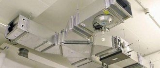
House ventilation losses
The key parameter in this case is the air exchange rate. Provided that the walls of the house are vapor-permeable, this value is equal to one.
The penetration of cold air into the house is carried out through supply ventilation. Exhaust ventilation helps warm air escape. The recuperator-heat exchanger reduces losses through ventilation. It does not allow heat to escape along with the outgoing air, and it heats the incoming air flows
It is envisaged that the air inside the building will be completely renewed in one hour. Buildings built according to the DIN standard have walls with vapor barriers, so here the air exchange rate is taken to be two.
There is a formula that determines heat loss through the ventilation system:
Qv = (V x Kv: 3600) x P x C x dT
Here the symbols mean the following:
- Qв - heat loss.
- V is the volume of the room in mᶾ.
- P is the air density. its value is taken equal to 1.2047 kg/mᶾ.
- Kv - air exchange rate.
- C is the specific heat capacity. It is equal to 1005 J/kg x C.
Based on the results of this calculation, it is possible to determine the power of the heat generator of the heating system. If the power value is too high, a ventilation device with a recuperator may be a way out of the situation. Let's look at a few examples for houses made of different materials.
Example of thermal engineering calculation No. 1
Let's calculate a residential building located in climatic region 1 (Russia), subdistrict 1B. All data is taken from table 1 of SNiP 23-01-99. The coldest temperature observed over five days with a probability of 0.92 is tн = -22⁰С.
In accordance with SNiP, the heating period (zop) lasts 148 days. The average temperature during the heating period with the average daily air temperature outside is 8⁰ - tot = -2.3⁰. The outside temperature during the heating season is tht = -4.4⁰.
Heat loss of a house is the most important point at the design stage. The choice of building materials and insulation depends on the results of the calculation. There are no zero losses, but you need to strive to ensure that they are as expedient as possible
The condition was stipulated that the temperature in the rooms of the house should be 22⁰. The house has two floors and walls 0.5 m thick. Its height is 7 m, its plan dimensions are 10 x 10 m. The material of the vertical enclosing structures is warm ceramics. For it, the thermal conductivity coefficient is 0.16 W/m x C.
Mineral wool was used as external insulation, 5 cm thick. The Kt value for it is 0.04 W/m x C. The number of window openings in the house is 15 pcs. 2.5 m² each.
Heat loss through walls
First of all, you need to determine the thermal resistance of both the ceramic wall and the insulation. In the first case, R1 = 0.5: 0.16 = 3.125 sq. m x C/W. In the second - R2 = 0.05: 0.04 = 1.25 sq. m x C/W. In general, for a vertical building envelope: R = R1 + R2 = 3.125 + 1.25 = 4.375 sq. m x C/W.
Since heat loss is directly proportional to the area of the enclosing structures, we calculate the area of the walls:
A = 10 x 4 x 7 – 15 x 2.5 = 242.5 m²
Now you can determine heat loss through the walls:
Qс = (242.5: 4.375) x (22 – (-22)) = 2438.9 W.
Heat loss through horizontal enclosing structures is calculated in a similar way. In the end, all the results are summed up.
If there is a basement, then heat loss through the foundation and floor will be less, since the calculation involves the temperature of the soil, not the outside air
If the basement under the floor of the first floor is heated, the floor does not need to be insulated. It is still better to line the basement walls with insulation so that the heat does not escape into the ground.
Determination of losses through ventilation
To simplify the calculation, they do not take into account the thickness of the walls, but simply determine the volume of air inside:
V = 10x10x7 = 700 mᶾ.
With an air exchange rate of Kv = 2, the heat loss will be:
Qв = (700 x 2) : 3600) x 1.2047 x 1005 x (22 – (-22)) = 20,776 W.
If Kv = 1:
Qв = (700 x 1) : 3600) x 1.2047 x 1005 x (22 – (-22)) = 10,358 W.
Rotary and plate heat exchangers provide effective ventilation of residential buildings. The efficiency of the former is higher, it reaches 90%.
Example of thermal engineering calculation No. 2
It is required to calculate losses through a 51 cm thick brick wall. It is insulated with a 10 cm layer of mineral wool. Outside - 18⁰, inside - 22⁰. The dimensions of the wall are 2.7 m in height and 4 m in length. The only outer wall of the room is oriented to the south; there are no external doors.
For brick, the thermal conductivity coefficient Kt = 0.58 W/mºC, for mineral wool - 0.04 W/mºC. Thermal Resistance:
R1 = 0.51: 0.58 = 0.879 sq. m x C/W. R2 = 0.1: 0.04 = 2.5 sq. m x C/W. In general, for a vertical building envelope: R = R1 + R2 = 0.879 + 2.5 = 3.379 sq. m x C/W.
External wall area A = 2.7 x 4 = 10.8 m²
Heat loss through the wall:
Qс = (10.8: 3.379) x (22 – (-18)) = 127.9 W.
To calculate losses through windows, the same formula is used, but their thermal resistance, as a rule, is indicated in the passport and does not need to be calculated.
In the thermal insulation of a house, windows are the “weak link”. A fairly large proportion of heat is lost through them. Multilayer double-glazed windows, heat-reflecting films, double frames will reduce losses, but even this will not help avoid heat loss completely
If the house has energy-saving windows measuring 1.5 x 1.5 m², oriented to the North, and the thermal resistance is 0.87 m2°C/W, then the losses will be:
Qо = (2.25: 0.87) x (22 – (-18)) = 103.4 t.
Example of thermal engineering calculation No. 3
Let's perform a thermal calculation of a wooden log building with a facade built from pine logs with a layer 0.22 m thick. The coefficient for this material is K = 0.15. In this situation, the heat loss will be:
R = 0.22: 0.15 = 1.47 m² x ⁰С/W.
The lowest temperature of the five-day period is -18⁰, for comfort in the house the temperature is set to 21⁰. The difference will be 39⁰. Based on an area of 120 m², the result will be:
Qс = 120 x 39: 1.47 = 3184 W.
For comparison, let’s determine the losses of a brick house. The coefficient for sand-lime brick is 0.72.
R = 0.22: 0.72 = 0.306 m² x ⁰С/W. Qс = 120 x 39: 0.306 = 15,294 W.
Under the same conditions, a wooden house is more economical. Sand-lime brick is not suitable for building walls here at all.
The wooden structure has a high heat capacity. Its enclosing structures maintain a comfortable temperature for a long time. Still, even a log house needs to be insulated and it is better to do this both inside and outside
Builders and architects recommend that you always do heat calculations when installing heating to ensure proper selection of equipment and at the stage of designing a house to select a suitable insulation system.
Heat calculation example No. 4
The house will be built in the Moscow region. For the calculation, a wall made of foam blocks was taken. Extruded polystyrene foam is used as insulation. The finishing of the structure is plaster on both sides. Its structure is limestone-sand.
Expanded polystyrene has a density of 24 kg/mᶾ.
Relative air humidity in the room is 55% at an average temperature of 20⁰. Layer thickness:
- plaster - 0.01 m;
- foam concrete - 0.2 m;
- expanded polystyrene - 0.065 m.
The task is to find the required and actual heat transfer resistance. The required Rtr is determined by substituting the values in the expression:
Rtr=a x GSOP+b
where GOSP is the degree-day of the heating season, a and b are coefficients taken from table No. 3 of the Code of Rules 50.13330.2012. Since the building is residential, a is 0.00035, b = 1.4.
GSOP is calculated using a formula taken from the same SP:
GOSP = (tv – tot) x zot.
In this formula, tв = 20⁰, tоt = -2.2⁰, zоt - 205 is the heating period in days. Hence:
GSOP = (20 – (-2.2)) x 205 = 4551⁰ C x day;
Rtr = 0.00035 x 4551 + 1.4 = 2.99 m2 x C/W.
Using table No. 2 SP50.13330.2012, determine the thermal conductivity coefficients for each layer of the wall:
- λb1 = 0.81 W/m ⁰С;
- λb2 = 0.26 W/m ⁰С;
- λb3 = 0.041 W/m ⁰С;
- λb4 = 0.81 W/m ⁰С.
The total conditional resistance to heat transfer Ro is equal to the sum of the resistances of all layers. It is calculated using the formula:
This formula is taken from SP 50.13330.2012. Here 1/av is the resistance to heat perception of internal surfaces. 1/an - the same as external, δ / λ - thermal resistance of the layer
Substituting the values we get: Rо arb. = 2.54 m2°C/W. Rф is determined by multiplying Ro by a coefficient r equal to 0.9:
Rf = 2.54 x 0.9 = 2.3 m2 x °C/W.
The result requires changing the design of the enclosing element, since the actual thermal resistance is less than the calculated one.
There are many computer services that speed up and simplify calculations.
Thermal calculations are directly related to determining the dew point. You will learn what it is and how to find its meaning from the article we recommend.
Influence of the air gap on thermal protection characteristics
When constructing a wall protected by slab insulation, it is possible to install a ventilated layer. It allows condensation to be removed from the material and prevents it from getting wet. The minimum gap thickness is 1 centimeter. This space is not enclosed and has direct communication with outside air.
If there is an air-ventilated layer, the calculation takes into account only those layers that are located before it on the warm air side. For example, a wall pie consists of plaster, internal masonry, insulation, an air gap and external masonry. Only plaster, internal masonry and insulation are taken into account. The outer layer of masonry comes after the ventilation gap and is therefore not taken into account. In this case, the external masonry performs only an aesthetic function and protects the insulation from external influences.
Important: when considering structures where the air space is enclosed, it is taken into account in the calculation. For example, in the case of window fillings. The air between the glasses plays the role of effective insulation.
Features of thermal engineering calculations of the external walls of a building by analyzing the insulation used
It is important to determine which insulation is best to use, as well as the required level of strength, durability, fire resistance, etc. parameters for building a house. Cold air that exists outside the house and warm air inside can, if the insulation and its thickness are chosen incorrectly, create condensation on the walls, this is especially true in basements where humidity is high. Such a side layer should be selected taking into account thermal conductivity.
An example will be given to help you understand the principle of calculations more easily. In the house, calculations are being made for a corner residential type room, in which there is 1 window measuring 8.12. The building was built in the Moscow region. The thickness of the walls is 200mm, the size of the area according to external criteria is 3000x3000.
It is necessary to find out the required power to warm one square meter of area. The answer will be Qsp = 70 W, if a thinner insulating material is installed, then more power will be required: 100 mm – Qsp = 103 W.
Such a side layer should be selected taking into account thermal conductivity.
Teremok program
To perform calculations using a personal computer, specialists often use the “Teremok” program for thermal engineering calculations. It exists in an online version and as an application for operating systems.
The program makes calculations based on all necessary regulatory documents. Working with the application is extremely simple. It allows you to work in two modes:
- calculation of the required insulation layer;
- checking an already thought-out design.
The database contains all the necessary characteristics for the settlements of our country; you just need to select the one you need. It is also necessary to choose the type of construction: external wall, attic roof, ceiling over a cold basement or attic.
When you click the continue work button, a new window appears, allowing you to “assemble” the structure. Many materials are available in the program memory. They are divided into three groups for ease of search: structural, thermal insulation and thermal insulation-structural. You only need to set the layer thickness; the program will indicate the thermal conductivity itself.
If the necessary materials are not available, you can add them yourself, knowing the thermal conductivity.
Before making calculations, you must select the type of calculation above the wall structure plate. Depending on this, the program will display either the thickness of the insulation or report the compliance of the building envelope with standards. After completing the calculations, you can generate a report in text format.
“Teremok” is very convenient to use and even a person without technical education can understand it. For specialists, it significantly reduces the time for calculations and preparing reports in electronic form.
The main advantage of the program is the fact that it is able to calculate the thickness of insulation not only of an external wall, but also of any structure. Each of the calculations has its own characteristics, and it is quite difficult for a non-professional to understand them all. To build a private house, you just need to master this application, and you don’t have to delve into all the complications. Calculation and checking of all enclosing surfaces will take no more than 10 minutes.
Formula for calculating thermal energy
In order to correctly calculate the required volume of heat for heating, it is important to take into account parameters such as the power of the heating boiler, as well as heat loss during operation. The formula for calculating the thermal energy required to heat a room is as follows: Mk = 1.2 * Tp (Mk is the power measured in kW that the heat generator has, Tp is the volume of heat loss from the residential structure, and 1.2 is the required reserve , which should be equal to 20%).
It is important to remember that the coefficient of 1.2 allows for the very possibility of a sharp decrease in pressure in the gas pipeline system during the cold season; in addition, this also includes potential heat losses, which are often caused by severe frosts, the special impact of which is observed due to insufficient thermal insulation of the room doors. The presence of such a reserve makes it possible to significantly vary temperature conditions.
It is impossible not to mention the fact that when calculating the heat energy expended, its losses will be completely uneven, so you should remember the following data:
- the most useful heat is lost through external walls - about 40% of the total volume;
- approximately 20% goes through window openings;
- heat leaves the room through the field in a volume equal to 10%;
- approximately 10% also comes out through the roof;
- Another area of heat loss is doorways and ventilation, through which about 20% of the heat can evaporate.
Air infiltration or building ventilation
All buildings, especially residential buildings, have the ability to “breathe”, that is, to be ventilated in various ways. This is due to the creation of rarefied air in the premises due to the installation of exhaust ducts in the structures of the house or chimneys. As you know, ventilation ducts are created in areas with increased emissions of contaminants, such as kitchens, bathrooms and restrooms.
Thus, when operating the ventilation system or during ventilation, the main rule of creating a favorable air environment in residential buildings is observed: the direction of movement of fresh air should be organized from rooms with constant occupancy in the direction of rooms with the maximum level of pollution.
That is, with proper air exchange, supply air enters the room through a window, ventilation valve or supply grille and is removed in kitchens and bathrooms.
When calculating heat loss, knowing which method of ventilation of residential premises will be chosen is of fundamental importance:
- Mechanical ventilation device with heated supply air.
- Infiltration is unorganized air exchange through leaks in walls, when windows are opened, or when using pre-installed air valves in wall construction or double-glazed windows.
If a balanced ventilation system is used in a residential building (when the volume of supply air is greater than or equal to the exhaust air, that is, any breakthrough of cold air into the living spaces is excluded), the air entering the living spaces is preheated in the ventilation unit. In this case, the power required to heat the ventilation is taken into account when calculating the power of the boiler equipment.
The ventilation heat load is calculated using the formula:
Q vent = c*p*L*(t1-t2) where, Q is the amount of heat required to heat the supply air, W;
c – heat capacity of air, J/kg*deg p – air density, kg/m3 L – supply air flow rate, m3/hour t1 and t2 – initial and final air temperatures, deg. If there is no organized air exchange in residential premises, then when calculating the heat loss of a building, the heat expended by the heating system to heat the infiltration air is taken into account. In this case, the heating of the air entering the premises is carried out by radiators of heating systems, that is, it is taken into account in their thermal load.
If sealed double-glazed windows without built-in air valves are installed in the premises, then heat losses due to air heating are nevertheless taken into account. This is due to the fact that in the case of short-term ventilation, the incoming cold air still needs to be heated.
For more comfortable ventilation, a supply wall valve is built in.
The amount of infiltration thermal energy is taken into account using several methods, and in the heat balance of the building the largest of the values is taken into account.
For example, the amount of heat to heat the air penetrating into the premises to compensate for natural exhaust is determined by the formula:
Q inf=0.28* L * p * c *( t nar- t pom), where, c – heat capacity of air, J/ kg*deg p — air density, kg/m?
tout – outside air temperature, degrees, troom – design room temperature, degrees, L – amount of infiltration air, m?/hour. The amount of air entering residential premises in winter is, as a rule, determined by the operation of natural exhaust systems, therefore in one case it is taken to be equal to the volume of extracted air.
The amount of hood in residential premises is determined in accordance with SNiP 41-01-2003 according to standard indicators for removing air from stoves and sanitary appliances.
- From a kitchen stove - electric 60 m?/hour or gas 90 m?/hour;
- From the bath and toilets 25 m?/hour
In the second case, this infiltration rate is determined based on the sanitary standard of fresh outdoor air, which must enter the premises to ensure the optimal and high-quality composition of the air environment in residential premises. This indicator is determined by the specific characteristic: 3 m?/hour per 1 m? living space.
The maximum air flow and, accordingly, the greater amount of heat loss due to infiltration are taken as the calculated value.
Example: Since the building considered in the example was built using a frame type with windows in wooden frames, when creating exhaust ventilation in the kitchen and bathrooms, the volume of infiltration will be quite high. Houses of this type are usually the most breathable.
The infiltration component is determined according to the above methods. The calculation is made for the entire residential building, provided that an electric stove is installed in the kitchen, and there is a bathroom and a bathroom on the ground floor.
That is, the volume of exhaust air according to the first method is Lext=60+25+25=110 m?/h,
and according to the second method, the sanitary norm of supply air is Lin = 3 m?/h * 62 m? (living area) = 186 m3/hour.
We take the maximum amount of air into the calculation.
Qinf=0.28*186*1.2*1.005*(22+28)=3,140 W, which is 44 W/m?.
Calculation of the standardized and specific heat-protective characteristics of a building
Before moving on to the calculations, let us highlight several excerpts from the regulatory literature.
Clause 5.1 of SP 50.13330.2012 states that the thermal protection shell of a building must meet the following requirements:
- The reduced heat transfer resistance of individual enclosing structures must be no less than the standardized values (element-by-element requirements).
- The specific thermal insulation characteristic of a building should not exceed the standardized value (complex requirement).
- The temperature on the internal surfaces of enclosing structures must not be lower than the minimum permissible values (sanitary and hygienic requirement).
- The requirements for thermal protection of the building will be met if conditions 1, 2 and 3 are met simultaneously.
The specific heat-protective characteristic of a building is the amount of heat equal to the loss of thermal energy through the heat-protective shell of the building of a unit of heated volume per unit of time with a temperature difference of 1°C.
Clause 5.5 SP 50.13330.2012 . The normalized value of the specific heat-protective characteristic of a building, k(tr ⁄ rev), W ⁄ (m³ × °C), should be taken depending on the heated volume of the building and the degree-day of the heating period of the construction area according to Table 7, taking into account the notes.
Table 7. Standardized values of the specific thermal insulation characteristics of a building:
| Heated volume of the building, Vot, m³ | Values of k(tr ⁄ rev), W ⁄ (m² × °С), at GSOP values, °С × day ⁄ year | ||||
| 1000 | 3000 | 5000 | 8000 | 12000 | |
| 150 | 1,206 | 0,892 | 0,708 | 0,541 | 0,321 |
| 300 | 0,957 | 0,708 | 0,562 | 0,429 | 0,326 |
| 600 | 0,759 | 0,562 | 0,446 | 0,341 | 0,259 |
| 1200 | 0,606 | 0,449 | 0,356 | 0,272 | 0,207 |
| 2500 | 0,486 | 0,360 | 0,286 | 0,218 | 0,166 |
| 6000 | 0,391 | 0,289 | 0,229 | 0,175 | 0,133 |
| 15 000 | 0,327 | 0,242 | 0,192 | 0,146 | 0,111 |
| 50 000 | 0,277 | 0,205 | 0,162 | 0,124 | 0,094 |
| 200 000 | 0,269 | 0,182 | 0,145 | 0,111 | 0,084 |
We launch “Calculation of the specific heat-protective characteristics of a building” :
As you can see, some of the original data was saved from the previous calculation. In fact, this calculation is part of the previous calculation. The data can be changed.
Using the data from the previous calculation, for further work you need to:
- Add a new building element (the “Add new” button).
- Or select a ready-made element from the directory (the “Select from directory” button). Let's select Construction No. 1 from the previous calculation.
- Fill in the column “Heated volume of the element, m³” and “Area of the fragment of the enclosing structure, m²”.
- Click the button “Calculation of specific heat protection characteristics”.
We get the result:
If you carried out the previous calculation, then you don’t have to use this calculation, since the data on the standardized and specific heat-shielding characteristics are calculated in the first program.
Calculation of thermal energy consumption for heating and ventilation
The last block of the program, like the previous one, uses part of the data from the first calculation. If desired, all parameters can be recalculated for a specific example. All items are clear and easy to fill out.
Calculation working window:
For calculations, the following fields must be filled in:
- Specific thermal protection characteristics of a building.
- Specific ventilation characteristics of the building.
- Specific characteristics of domestic heat emissions of a building.
- Specific characteristics of heat input into a building from solar radiation.
- Heat gain reduction coefficient due to thermal inertia of enclosing structures.
- Efficiency coefficient of automatic regulation of heat supply in heating systems.
- A coefficient that takes into account the reduction in heat consumption of residential buildings in the presence of apartment-by-apartment metering of thermal energy.
- A coefficient that takes into account the additional heat consumption of the heating system associated with the discreteness of the nominal heat flow of the range of heating devices, their additional heat loss through the radiator sections of the fences, increased air temperature in corner rooms, heat loss of pipelines passing through unheated rooms.
- Average floor height of a building.
Download the thermotechnical calculation program LIT THERMO ENGINEER
Software for performing thermal engineering calculations of enclosing structures when designing buildings and structures LIT Thermo Engineer:
- Version: 1.2.5.
- Last updated: 09/27/2016.
- Platform: Windows 2000 / XP / Vista / 7 / 8 / 8.1 / 10.
- License type: Freeware.
- Size: 27.7 MB.
Program features:
- Integration with CAD KOMPAS 3D.
- Standalone or run from a CAD library.
- Possibility of exporting calculation results to PDF format.
The installation process of the program is simple.
Let's highlight the main stages:
- Run the installer setup.exe.
- Selecting the installation folder.
- Installation.