Tips for drawing a heating diagram
For those who nevertheless decided to make a diagram on their own and ask, for example, me, to criticize or correct it, in this article I will give you several key recommendations using the example of one heating scheme for a private house sent to me.
In order to initially correctly draw a heating diagram for a private house, you need to decide what kind of heating system you will have. This comes from what main energy carrier you have. I talked about this in detail and showed it in the course “How to choose a heating system for your home”
So, if you have determined your energy carrier and the heating system itself, then let’s move on to drawing it.
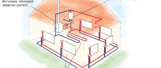
The fact is that, regardless of what kind of boiler you have as the main one and whether there is a backup boiler, you need to draw a coplanar distribution manifold. Because you have no guarantees for the long-term use of a separate boiler. And your main boiler will become a backup boiler tomorrow.
Then it will be clear how much space is needed for the entire heating system of a private house. And for all the convenience, for the future use of your heating system based on a coplanar collector, when manufacturing or ordering it, you will be able to install from one to several spare circuits for connecting boilers or heating systems.
You can find out more about selecting or making your own distribution manifold here.
Next, you need to place the collector on your sheet on which you will draw your heating diagram. I propose to take an A4 sheet and separately draw a collector on a small piece of paper and, placing it on a large sheet, determine its location.
The collector on the plan can be placed in the middle if you have floor-standing boilers or, as in our plan, at the bottom if the boilers are wall-mounted.
Now we arrange the heating circuits in such blocks in the form of squares or rectangles. We sign: Radiators 2nd floor, Warm floors 1st floor, indirect heating boiler and so on.
You can also highlight the collector itself with boilers and a boiler, for example, specifically related to the location in the boiler room.
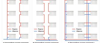
Now you need to draw exactly your chosen heating system diagrams. For example, in our case, this is a two-pipe radiator heating system, a heated floor system, and an indirect heating boiler.
Afterwards, it is necessary to place on the diagram of the heating system of a private house all additional equipment in the form of taps, pumps, pressure gauges, thermometers, expansion tanks, safety devices and instrumentation devices.
Flow
Flow
– a program for calculating heating systems, presented by a domestic developer of specialized software.
This software package allows you to create and simulate a working diagram of a heating system of any configuration, including underfloor heating. The features of this software are:
- Output the result for viewing and editing in AutoCad or Word.
- The ability to carry out all the calculations necessary to create a competent RM thanks to a rich toolkit.
- Availability of databases with characteristics of equipment and components from several manufacturers (including domestic ones).
- Possibility of creating CO schemes based on several types of coolant.
User-friendly interface
The Project Studio CS Heating program has a familiar interface, which allows you to minimize the time it takes to implement it. The user works with standard drop-down menus, toolbars, and the command line. In addition, Project Studio CS Heating implements service functions for creating models of heating systems, such as a context menu, tracking and object snapping modes, etc.
Equipment placement
In accordance with the identified needs of various rooms of the building for heating systems, engineers select and arrange equipment throughout the entire model of the designed facility. One of the advantages of Renga is the independence of the work of specialists from “blank” catalogs of heating network objects. The program implements a universal tool “Styles”, which allows you to create all the necessary types of equipment from any manufacturer. In a matter of minutes, by changing the parameters of the system type, the user receives the instance required in the project.
At the same time, if necessary, it is possible to import three-dimensional objects into the model, which the engineer can use in the created model. For this purpose, the system is integrated with other software products and imported in .ifc, .c3d, . step, .sat, .iges, etc. In addition, Renga presents ready-made catalogs of leading manufacturers of engineered heating equipment.
Open Databases
The Project Studio CS Heating database contains about 6,000 elements of heating systems. The most popular domestic and foreign manufacturers of heating equipment in Russia are presented, such as Honeywell, Danfoss, Zetkama, VAN-TUBO, Wilo, Grundfos, OJSC SANTEKHPROM, Global, Giel, etc.
All Project Studio CS Heating databases are open for user addition. At the same time, to create new equipment or edit existing equipment, there is no need to have programming skills. The ability to work in a simple spreadsheet editor is enough.
Design stages
To create a competent CO it is necessary to perform the following types of work:
- Choose the most suitable heating system for a particular building.
- Create a sketch with tracing of the main pipeline and risers.
- Carry out hydrodynamic thermotechnical calculations for the competent selection of equipment, materials and diameters of the pipeline and other elements of the system.
- Create a design drawing linked to the building layout.
The design of heating and ventilation systems begins with the preparation of technical specifications, which are formed on the basis of site inspection data, measurements and the client’s wishes. After this, the specialist offers the customer the most suitable option (sketch) of the heating system with a full feasibility study. When the possible costs of creating a CO are agreed upon with the customer, his comments and wishes are taken into account, the design specialist proceeds to the most important step - calculations, on the basis of which diagrams of the CO and a plan for laying utilities are drawn up.
After consultation with the client, the specialist draws up a specification of materials, equipment and prepares a package of documents for approval by the relevant authorities. The last stage in creating a project is to engage a subcontractor to perform installation and commissioning work.
Regarding preliminary work.
Due to the fact that hydraulic calculations require a lot of time and effort, we need to first perform some calculations:
- Determine the balance of premises and rooms that are heated.
- Decide on the type of heating equipment and heat exchanger. Arrange them according to the general plan of the building.
- Before you begin the calculation, you should select the pipelines and decide on the configuration of the heating system as a whole.
- It is necessary to make a drawing of the system, preferably an axonometric diagram. In it, indicate the length of the sections, numbers and load magnitude.
- The circulation ring should also be installed in advance.
Important! If the calculation concerns a wooden house, then there are no differences between it and a brick, concrete, etc.
will not be.
Decor
Project StudioCS Heating.
Design of the plan The Project StudioCS Heating program fully complies with the requirements of domestic regulatory documents. All tabular forms comply with GOST 21.602−2011 and GOST 21.110−2013. The placement of the frame with the main inscription on the drawing is carried out in accordance with GOST R 21.1101−2013.
Project StudioCS Heating. Design of axonometry
The program implements the following functionality: slope (information is taken from the pipeline), elevation mark (automatically reading the real height of the object), text element (insertion of pipeline designations T1 and T2 into pipes) and a special leader.
UGO table
The program implements automatic generation of a table of UGOs used in the project. The table is generated both for each floor and for the entire project.
The generated table is installed on the active *.dwg file in the CAD workspace.
Design and procedure for performing work on the arrangement of heating systems
When designing the heating of a private house, you cannot make mistakes, even the slightest. The least they can manifest themselves in is extra cash costs to eliminate them. Large buildings require more time for calculations, planning, and the involvement of many specialists, including related ones. But even small houses can lose a lot if the issue of creating a project is approached superficially or frivolously.
Even those who are used to doing everything on their own will not risk installing a heating system without preliminary calculations, a working drawing, or a sketch of the entire heating system.
In any case, the procedure for arranging the heating system is as follows:
- Development and detailed calculation of the project in detail.
- Purchase of necessary pipe equipment and components.
- Installation and construction operations and work are under the strict supervision of specialists.
- Acceptance of finished work by the relevant services.
- First launch, eliminating defects if necessary.
- The final launch and acceptance of the project by the user - delivery of the finished work.
- Drawing up a warranty and post-warranty service agreement and, if necessary, carrying out a full range of repair work.
The cost and type of project will depend on the location of the region, climatic conditions, the size of the heated area, the complexity of installation and construction work, the use of equipment and special equipment.
If the development of a heating project can only be entrusted to specialized specialists, then choosing the type of fuel, and, accordingly, the type of boiler, is entirely your task. However, if there are any doubts, then consultations with professionals will be useful.
The working project involves more than just heating distribution in rooms - it includes calculations and equipment drawings Source liveinternet.ru
Calculations and work that need to be done in advance
Hydraulic calculation is the most time-consuming and complex design stage.
- Firstly, the balance of heated rooms and premises is determined.
- Secondly, it is necessary to select the type of heat exchangers or heating devices, and also arrange them on the house plan.
- Thirdly, calculating the heating of a private house assumes that a choice has already been made regarding the configuration of the system, types of pipelines and fittings (control and shut-off).
- Fourthly, a drawing of the heating system must be made. It is best if it is an axonometric diagram. It should indicate numbers, length of calculation sections and thermal loads.
- Fifth, the main circulation ring is installed. This is a closed loop that includes successive sections of pipeline directed to the instrument riser (when considering a single-pipe system) or to the most distant heating device (if there is a two-pipe system) and back to the heat source.
Duct selection program Ducter 2.5
Ducter 2.5
This program for selecting ventilation equipment calculates the diameters of air duct sections. The user enters the maximum values of flow velocity in the air ducts, height differences when calculating natural ventilation or the CMC of the segment. Based on this information, the program selects ventilation equipment of standard diameter in accordance with VSN 353-86 linearly. Thus, the final decision on the diameter remains with the specialist.
If an air duct with non-standard parameters is needed, the program will also help: one parameter is entered, the rest are selected. The selection step is set in the settings.
You can set one of several options for displaying the dimensions of each area.
Program versions from Ducter 3 and higher for selecting equipment will help you fully calculate the entire ventilation system.
Program for drawing ventilation CADvent
CADVent
This ventilation drawing program is based on the powerful and sophisticated AutoCAD. Along with the development of AutoCAD, CADvent is modified and improved, and new features are added. These are professional ventilation drawing, calculation and presentation programs designed for engineers working in the design and development of ventilation, air conditioning and heating systems.
CADvent functions:
- calculation of the cross-section of air ducts;
- pressure loss calculation;
- acoustic calculation;
- creation of a 2D drawing with the necessary symbols;
- 3D modeling;
- specification for elements, which can be transferred to MS excel;
- creating presentations.
The CADvent program provides the ability to make any changes to a ready-made project, change design parameters, and add new elements. It can be combined with the DIMsilencer programs (a program for selecting a noise suppressor in a ventilation system) and DIMcomfort (selects air distributors, taking into account the flow speed and noise in places where people are located).
Users note ease of use, but there is a lack of Russification, as well as the ability to create an axonometric projection.
Watch the video about another program called Comfort-B.
Reports “Heating devices” and “List of heating devices”
Project Studio CS Heating provides reports “Heating devices” and “List of heating devices” with the ability to display them by floor. This function allows installers to be informed in advance which devices and with what piping will need to be delivered to a certain floor, which will help significantly speed up the installation of the heating system. Reports can be output to Excel.
About special programs for calculations
Oventrop CO program
This is an absolutely free program that is widely used to calculate a country house. You just need to first set all the necessary settings and specify heating devices and pipes - then you can easily develop new systems. Moreover, if you wish, you can adjust the existing system. This is done as follows: the power of existing devices is selected in accordance with the requirements of the heated building.
Both design methods are perfectly combined in a single software, which makes it possible to create new designs and adjust old ones. Regardless of the method, the program itself selects the fitting settings. Regarding the calculations that interest us, Oventrop CO provides simply unlimited possibilities - from analyzing coolant flow to pipe diameter. All information is displayed in the form of pictures, tables or diagrams.
HERZ CO program
Another representative of free programs that allows you to calculate any kind of heating system. The utility is characterized by the fact that it allows such calculations to be made even in new or recently reconstructed facilities in which the coolant is glycol. It meets all international requirements, therefore, it has all the necessary certificates.
Below are the main opportunities that the German HERZ CO can provide you with
- Select the pipeline diameter.
- Reduce the pressure in the circulation rings by automatically selecting valve parameters.
- Set up pressure difference “regulators”.
- Take into account the necessary parameters of thermostatic valves.
- Analyze future coolant flow, as well as determine the pressure drop in the system.
- Calculate the hydraulic resistance of the circulation rings.
To make it more convenient for you to use the program, all information can be entered graphically. As a result, the utility will give you a floor plan of the building.
Important information! Another distinctive feature of the program is the so-called contextual help. It makes it possible to learn more about the entered command or any indicator.
It is also possible to open several windows at once (which is very rare for this kind of product), so you can study several types of information at the same time. It is possible to work with printers and plotters - it is extremely simply organized, each sheet that is planned to be printed can be previewed.
Automatic generation of specifications and spreadsheet documents
Based on the three-dimensional information model developed by Model Studio CS, a complete set of tabular documentation is generated - specifications of equipment and materials, custom specifications, equipment explanations, room air exchange table and others. Generation occurs completely automatically; the user only needs to select the required template and application format into which the final version will be uploaded. Currently, it is supported to save spreadsheet documents in MS Word, MS Excel, Rich Text Format (RTF) and directly on a drawing in the form of AutoCAD or nanoCAD tables.
For ease of working with the model, preparing and uploading spreadsheet documents, Model Studio CS provides a special interactive tool, Specifier. A specifier is a special dialog box that is always available for viewing, in which the composition of the current three-dimensional model is displayed in a tabular form of a given form (if necessary, the user can specify his own version of the table).
By selecting a position in the specifier, model objects that correspond to this position are automatically selected, which makes editing attribute information in the model more convenient and efficient. Some parameters can be assigned in the specifier itself, for example, the position field, which is filled in by the user manually or automatically in order.
Tools in the Valtec Main Menu
Valtec, like any other program, has a main menu at the top.
We click on the “File” button and in the submenu that opens we see standard tools known to any computer user from other programs:
The “Calculator” program built into Windows is launched to perform calculations:
Using the "Converter" we will convert one unit of measurement to another:
There are three columns here:
On the far left we select the physical quantity we are working with, for example, pressure. In the middle column is the unit from which you need to convert (for example, Pascals - Pa), and in the right column - into which you need to convert (for example, to technical atmospheres). In the upper left corner of the calculator there are two lines, in the upper one we will enter the value obtained during the calculations, and in the lower one we will immediately display the conversion to the required units of measurement... But we’ll talk about all this in due time, when it comes to practice.
In the meantime, we continue to get acquainted with the “Tools” menu. "Form generator":
This is necessary for designers carrying out custom projects. If we do heating only in our house, then we don’t need the “Form Generator”.
The next button in the main menu of the Valtec program is “Styles”:
It controls the appearance of the program window - it adapts it to the software that is installed on your computer. For me, this is an unnecessary gadget, because I am one of those for whom the main thing is not “checkers”, but getting there. And you decide for yourself.
Let's take a closer look at the tools located under this button.
In “Climatology” we select the construction area:
Heat loss in a house depends not only on the materials of the walls and other structures, but also on the climate of the area where the building is located. Consequently, the requirements for the heating system depend on the climate.
In the left column we find the area in which we live (republic, region, region, city). If our settlement is not here, then choose the nearest one.
"Materials". Here are the parameters of different building materials used in house designs. That is why, when collecting initial data (see previous materials on design), we listed the materials of walls, floors, and ceilings:
Openings tool. Here is information on door and window openings:
"Pipes". Here you can find information about the parameters of pipes used in heating systems: internal and external dimensions, resistance coefficients, roughness of internal surfaces:
We will need this for hydraulic calculations - to determine the power of the circulation pump.
"Coolants". Actually, there is nothing here except the characteristics of those coolants that can be poured into the heating system of a house:
These characteristics are heat capacity, density, viscosity.
Water is not always used as a coolant; it happens that antifreeze, popularly called “anti-freeze,” is poured into the system. We’ll talk about choosing a coolant in a separate article.
“Consumers” are not needed to calculate the heating system, since this tool is for calculating water supply systems:
"KMR" (local resistance coefficients):
Any heating device (radiator, valve, thermostat, etc.) creates resistance to the movement of the coolant, and these resistances must be taken into account in order to correctly select the power of the circulation pump.
"DIN devices". This, like “Consumers”, applies more to water supply systems:
HERZ calculation program HERZ official website of HERZ Armaturen in our country
We also inform you that the HERZ valve database in the RAUCAD program has been updated. If you have any questions about obtaining a new database, please contact the engineer of the technical support group of the internal engineering systems department, Moscow, tel. (ext. 203).
HERZ CO program
The HERZ CO program is needed for hydraulic calculations of single- and two-pipe heating systems and cooling, during the design of new systems, as well as for regulating existing ones in reconstructed buildings (for example, after insulating a building), it has the ability to calculate systems where the heat carrier is glycol mixtures.
The program makes it possible to perform all hydraulic calculations of equipment, within the framework of which:
diameters of pipelines are selected; water flow in the designed equipment is analyzed; pressure losses in the equipment are determined; the hydraulic resistance of the circulation rings is determined, taking into account the gravitational pressure associated with cooling of water in pipelines and heat consumers; settings of pressure difference regulators installed in places selected by the designer (base of risers, branches, etc.) are selected; the required authorities of thermostatic valves are taken into account; excess pressure in the circulation rings is reduced by selecting valve presets; The need to equip an appropriate hydraulic resistance in the area with the heat consumer is taken into account.
The program uses many solutions to make work easier and better. The most important of them are:
- graphical data entry process;
- presentation of calculation results on diagrams and floor plans;
- a developed contextual help system that provides information both about individual program commands and a hint regarding the entered data;
- multi-window environment, it allows you to simultaneously view many types of data, results, etc.;
- usual cooperation with printer and plotter, function of previewing pages before printing and outputting to plotter;
- luxurious diagnostics of errors and the function of their automated search, both in the table and in the diagram;
- quick access to catalog data of pipes, radiators and fittings.
HERZ OZC program
The HERZ OZC program is used to determine the estimated heat losses of individual rooms in a building, as well as the entire structure. The calculation is carried out in accordance with the appropriate standards. The program does:
- calculation of heat transfer coefficients for walls, floors, roofs and ceilings between the top floor and the attic;
- calculation of heat loss for individual premises;
- calculation of heat loss of the entire building.
The program uses many solutions to make work easier and better. The most important of them are:
- developed help system;
- luxurious catalog of materials for construction;
- function of automated determination of resistance to heat transfer, resistance of air layers of floors between the top floor and the attic, soil resistance;
- function for automated creation of the next floors, copying of rooms, and also selection of rooms, for example, if while entering data about a room it is necessary to call another room;
- option for automated distribution of heat losses from a room with a small need for heating capacity (for example, a corridor) to adjacent rooms, which provides the opportunity to directly transfer calculation results to the HERZ CO program
The program provides the opportunity to carry out calculations of heat losses of huge buildings.
The following are restrictions regarding the data:
Limit number of defined fences: 16300 Limit number of layers in one fence: 16300 Limit number of rooms: 16300 Limit number of fences in one room: 16300
The results of heat loss calculations are the output data for the HERZ CO program used for designing district heating systems.
Working with floors, rooms and risers
It is possible to download rooms via IFC format. Also, the engineer can independently determine the contours of the room in both automatic and manual modes. You can automatically number rooms if this has not been done previously. And all characteristics and data for all floors and rooms are displayed in one dialog box Building/object model
. Here it is also possible to change the characteristics (properties) of each floor or room - now there is no need to open each drawing separately.
The Interfloor Connections Wizard is used to view and analyze all designed risers in a building and edit their properties.
Free programs for hydraulic calculations of a home heating system
Calculating heating in a private house is characterized by complexity. He is required to determine hydraulic pressure losses, calculate the diameter of the pipeline system and link all structural elements.
To simplify the calculations, a heating calculation program is used. You can choose among several services. Thus, calculations are made online. However, some programs are offered free of charge.
Using special software, the following data is obtained:
- Required diameter of the pipeline line.
- Dimensions of heating elements.
- Specific valve for balancing.
- Setting up control parts.
- Indicators of control of thermostatic valves.
- Pressure change sensor values.
Hydraulic heating calculation
Overview of heating programs
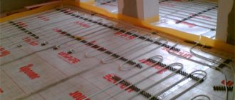
Complex floor heating scheme
The choice of software for heat supply should begin with determining the conditions for its operation. In some cases, it is enough to make only a hydraulic calculation for certain sections of the system. But to organize complex systems you will need a professional heating drawing program.
Having decided on the functionality, it is necessary to select the right software, comparing its technical characteristics with the capabilities of the computer. The vast majority of software has minimum requirements for this indicator. However, there are complexes that require a powerful video card and large disk space.
Some shareware programs for designing heating systems have a time limit on use. Upon completion of this period, access to the functionality will be fully or partially limited.
Instal-Therm HCR
Instal-Therm HCR program
This heating design program for a private home has advanced functionality and its interface is user-friendly. An important factor is the ability to connect additional modules for the integrated design of not only heating, but also water supply and ventilation of the house.
To work with the software, you must first enter the initial data. To do this, you can use an axonometric scan or do it in projection. When the input is complete, the calculated parameter is selected. This program for calculating the heating system of a private house can calculate a specific characteristic of the system, or do a comprehensive design:
The advantage of using this heating simulation program is that you can get the full version for free. To do this, you need to contact representatives of Wavin Ekoplastik . Registration keys are issued for a year - then you need to get new ones.
The heating design program must include modern requirements for the heat supply system. In particular, GOST and SNiP standards.
Flow
Interface of the Potok program
Of particular interest is the software package developed by the domestic one. It has great capabilities for calculating the main parameters of the heat supply system. But the uniqueness of this program for calculating heating in a private house lies in its versatility.
This software is intended for modeling and drawing up working diagrams of one-pipe, two-pipe, beam systems. The function of designing a water heated floor will be useful. Unlike specialized programs for heating design, Potok is truly universal. It contains the parameters of pipes and heating supply components from more than one manufacturer, which is typical for other software. Therefore, with its help you can make the optimal scheme for a specific house or apartment.
The advantages of using the heating drawing program Thread are as follows:
The disadvantage is the cost of the software package. Currently it is 37 thousand rubles. The demo version offered by the developers has very limited functionality. Once your license expires, you can renew it for a much lower fee.
Herz CO
Currently, this is the most convenient program for drawing up heating schemes. Its difference from other software lies in its convenient graphical interface. In addition to heating systems, it can perform all the necessary calculations to create cooling at home.
Using this heating design program for a private home, you can calculate hydraulic parameters with great accuracy. To do this, it is necessary to initially adapt the software shell for specific calculations. It is best to download the database from the developer's website. After installing and entering the primary parameters, the program will calculate the heating system of a private house according to the following criteria:
Using such programs to design heating systems will help you avoid the most common mistakes. For this purpose, an error diagnostic system was introduced in this complex, as well as automatic correction with user notification.
Experts recommend using the Herz CO program to simulate heat supply systems when designing apartment buildings. Currently, the maximum number of premises for calculation is 16,300.
Rehau software systems
Rehau company offers design of all types of engineering systems for residential and industrial buildings. These include several programs for calculating heat supply in a private home. It should be noted that only components from this manufacturer are used as heating components.
To perform calculations correctly, it is recommended to use several programs for creating heating systems. These include the following complexes:
The main disadvantage of all the above-described heating design programs for a private cottage is the limited set of components. Basically, the characteristics of only those products produced by Rehau are given.
In the video you can see an example of heating calculation using the RauCad software package:
Source
Why do you need virtual home designers?
First of all, builders, architects and interior designers use software designed for designing models of residential buildings, interior filling of rooms and arrangement of local areas. Program parameters for designing a convenient and comfortable home allow you to make changes, changing the building model, the location of rooms, and correcting defects; on paper this will be much more difficult. Other designer functionality includes:
- Selecting the optimal options for the location of the house on the site.
- Selection of the correct configuration and size of the roof, openings for doors and windows.
- Creation of a unique house model and interior space layout.
- Selection of building materials taking into account the climate, weather and characteristics of a particular region.
- Drawing up interior compositions that will suit all residents of the house.
- Correct location of swimming pools, gazebos, patios, and playgrounds in areas near houses.
- Quickly mastering the skills of working in the program allows novice designers and builders to understand the principles of drawing up drawings and planning rooms.
Using programs for virtual construction of a house model will allow builders who want to build their own housing to save money. Construction can be done by professionals, but it is specialized software that determines exactly what materials are needed for the foundation, walls, roof, and interior floors.