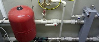
Due to improper operation, temperature changes and pressure surges, failures may occur in the operation of autonomous heating systems. The negative consequences in such situations are critical: from the breakdown of individual components to the destruction of buildings and a serious threat to life.
A safety valve in the heating system will help eliminate dangerous risks. What is it and what is its principle of operation? We will consider these questions in our article. We will also analyze the types of such valves and indicate the main differences between them, consider the rules for installation in the heating system and provide recommendations for selecting and configuring safety valves.
Purpose and installation location
Closed heating systems operate under a certain pressure.
A significant increase in operating pressure leads to equipment failure. Connections may leak, plastic parts and elements may burst. In the most unfavorable situations, the boiler heat exchanger may explode. This is already very dangerous and threatens not only the floor flooded with hot coolant, but also burns. After all, the temperature is serious. The overpressure relief valve must protect the heating system from excessively high pressure. As long as the system parameters are within normal limits, it does not manifest itself in any way. Although the pressure in the system gradually increases from the moment the boiler starts, the expansion tank compensates for it, maintaining a stable state of the system. But it may not do this indefinitely, although, with proper calculation, it is enough for standard situations. If the expander fails to cope with the task, the pressure begins to rise. When it exceeds the threshold, the excess pressure relief valve is activated. It simply releases part of the coolant, thereby stabilizing the emergency situation.
That is, the excess pressure relief valve in the heating system works in emergency situations. That is why it is also called “emergency”. And also “discharge”, “drain”, “protective” and “explosive”. All these are names of the same device.
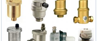
What does a safety (emergency) valve for heating look like?
As is clear from the description, when the pressure increases above a certain limit, a certain amount of coolant is simply released from the system. If you came to the boiler room and a puddle formed under the emergency valve, it means there was an emergency situation during which the pressure increased. No other alarm
So these traces are worth paying attention to. It is worth immediately checking the functionality of the valve itself and the membrane tank
Most likely, they are the reason. If you do not pay attention to these symptoms, after a while you may encounter problems: either something will “fly” in the system, or the water heating boiler will rupture.
Installation location of the emergency heating valve - on the supply pipeline, near the boiler
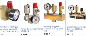
Of all the equipment in an individual heating system, the most dangerous is the boiler. Therefore, the excess pressure relief valve is installed either directly on the boiler itself (if there is an appropriate outlet for installation) or on the supply line immediately after the boiler. The distance is small - 20-30 cm from the body. If the boiler does not have this type of fittings (indicated in the description), then it is installed in the so-called safety group or placed separately. The safety group is placed at the outlet from the supply line immediately after the boiler (before the first branch and any other device), on which a pressure gauge, automatic air vent and excess pressure relief valve are installed.
When protection is needed
When installing equipment, it is best to immediately install an independent valve.
It is necessary to install the device on the hot water supply system if the water is heated not by the flow method, but from a heating boiler.
Individual closed circuits heated by a heat exchanger or other heat source are also equipped with a fuse.
The valve is needed in various hydraulic connections operating under pressure or with a compressor pump.
Manufacturers
The greatest demand is for security groups from Valtec and Watts. Their products are distinguished by high quality workmanship and reliability. For example, VT.460.0.0 from Valtec is used for heating systems with a nominal pressure of up to 10 bar. The maximum temperature of use should not exceed +120°C. Steam, water or a special liquid can be used as a coolant.
The emergency valve has a fixed setting of 3 bar. The body of the safety group is brass, nickel plated. The thread for connection is internal, size 1″. The cost of the VT.460.0.0 group starts from 1,700 rubles.
Security Groups from Watts
The WattsKSG-MS security group has similar characteristics. The body is made of brass, but unlike the previous device, it is located in a heat-insulating casing. The emergency valve response threshold is 3 bar.
When installing the safety group and other parts of the heating system, you must strictly follow the instructions supplied with them from the manufacturer. Because if installed incorrectly, the system will not work properly, or an error made during installation will lead to its breakdown.
Advantages and disadvantages
The relief valve has the following advantages:
- eliminates water hammer and pressure surges;
- prevent the appearance of air pockets in the liquid media transportation system;
- simple design that is easy to maintain and repair;
- relatively low cost;
- possibility of automatic control and pressure release;
- simple installation technology;
- unpretentiousness to operating conditions;
- do not require frequent maintenance.
Flaws:
- presence of operating error;
- increased wear of critical parts;
- limited service life.
Simple valve design
Recommendations for selection and installation
Since not all manufacturers of heating equipment complete their products with a safety group, you often have to make the choice of a safety valve for the heating system yourself. To do this, it is necessary to study the technical characteristics of the boiler installation, namely, know its thermal power and maximum coolant pressure.
For reference. Most solid fuel heat generators of well-known brands have a maximum pressure of 3 Bar. An exception is STROPUVA long-burning boilers, whose limit is 2 Bar.
The best option is to purchase a valve with pressure control that covers a certain range. The regulation limits must include the value for your boiler. Then you need to select a product according to the power of the thermal installation, but it’s difficult to make a mistake here. The manufacturer's instructions always indicate the limits of the thermal power of the units with which a valve of a particular diameter can operate.
It is strictly forbidden to install shut-off valves on the section of the pipeline from the boiler to the place where the excess pressure relief valve is installed. In addition, you cannot install the device after the circulation pump; do not forget that the latter is not able to pump the steam-water mixture.
To prevent splashing of water throughout the furnace room, it is recommended to attach a tube to the outlet of the valve that drains the discharge into the sewer. If you want to visually control the process, then you can place a special drain funnel on the vertical section of the tube with a visible break in the stream.
Rules for installation and operation of the device
Installation of the product on the pipeline must be done with sealing gaskets without distortions. The working substance passing through the valve must be free of mechanical inclusions and abrasive particles. It is advisable to install a mesh filter of the appropriate diameter at the inlet to the system. Installation of the device with a spring mechanism is carried out strictly in a vertical position, with the lid facing up. For the lever included in the design of the lever-load device, it is necessary to ensure a horizontal position. It is not recommended to place shut-off elements in the form of taps, gate valves, or levers in front of a relief valve.
To eliminate excess liquid, it is necessary to install an additional outlet used to drain water into the sewer pipeline or return pipe.
During operation, it is necessary to periodically inspect the device, since in products with a spring mechanism, displacement of the plate towards the walls of the housing may occur.
Required tools and materials
To install the valve you will need:
- adjustable wrench;
- fum - ribbon or tow;
- special paste for sealing joints.
For example, let's look at the installation diagram of the device in front of the hot water heater in the apartment.
Work progress
Each product designed for releasing excess pressure is equipped with installation instructions, which should be carefully studied before starting work. Before installation, you also need to disconnect the water heater from the network and drain the water from it. The valve must be placed on the cold water supply up to the shut-off valve. The valve installation sequence is as follows:
- marking the installation site;
- removing a part of the pipe of a size corresponding to the length of the device body;
- threading the ends of pipes:
- covering the threaded part with tow or fum tape;
- screwing the valve onto the pipe thread;
- connecting to another pipe a pipe leading to the sewer system.
- tightening the threaded connection using an adjustable wrench;
- sealing the joint with a special paste;
- setting up the device in accordance with the passport values (if necessary).
Types of valves
Under the influence of the pressure of the superheated coolant, the membrane rises and is discharged into the drain.
The following types of mechanisms are suitable for installation in a heating system:
Discharge
A relief valve for heating operates according to the principle of the simplest protective device: the resulting gases or coolant, after reaching the excess pressure limit, press on the membrane and leave the system.
Lever-load
Suitable for pipes with a diameter of 0.2 m and larger. In heating systems in which the heat source is a boiler, lever-load type valves are not installed. In these mechanisms, a load is used to increase the effect on the membrane. In order to determine the pressure force at which the valve is activated, adjustment is carried out by changing the mass of the load.
Back
An emergency device of this type is installed to relieve excessive pressure. Additionally, it allows the coolant to move through the pipes in only one flow, determined by the design.
Spring
In a ball valve design, the excess pressure depends on the weight and size of the ball
The most popular device is used for an autonomous heating system. The device is durable and has a simple design: the rod is pressed by a spring. It is possible to configure the device’s response parameters using the existing control mechanism. The force of impact is determined by the degree of compression.
Ball
It has a very simple design: the hole is closed with an ordinary steel ball (by weight). The valve response pressure is pre-calculated; it directly depends on the diameter of the hole and the weight of the ball.
Air
The purpose of such a valve is to free the system from the resulting gases that create plugs and prevent the heating from working properly.
What to do if water drips through the relief valve
The nature of the problem depends on whether the water from the safety valve is dripping or flowing in a stream.
If the coolant is dripping, this indicates normal operation of the emergency valves, but the heating system is operating at the limit, since the temperature in the coolant in it is increased and the pressure exceeds the norm. It’s easy to check whether the drops are the natural operation of the mechanism - just lower the operating temperature, allowing the coolant to cool. If the water drainage stops, then everything is in order, you just need to prevent further reheating.
A mechanism clogged due to contaminated coolant. Particles of sand and dirt prevent the rod from completely closing, which causes leakage.
If the drops do not stop or the coolant is discharged in large quantities, in a stream, this indicates a malfunction of the safety valve: the spring, rubber or silicone seal are worn out, the fitting is clogged, as a result of which it does not fit tightly. It is not recommended to disassemble the mechanism yourself; in this case, it is necessary to replace the relief valve (issue price 400-900 rubles).
The main thing in a moonshine still is safety.
Quickly navigate to the article
Home brewing is gaining more and more fans. The number of amateurs and professionals is growing. But you shouldn’t lose sight of the safety of making moonshine. The pressure relief valve is designed to do just that. After all, there are enough cases when moonshine stills exploded in apartments of residential buildings. And this happens not only because of inexperience and irresponsibility, but also because of homemade low-quality devices.
The pressure relief valve prevents mechanical damage to the unit due to excess pressure. This happens by releasing excess gas. This happens automatically. In this case, the emission of steam stops when the working medium reaches an operating state.
Excess steam can occur not only due to improper operation. For example, the use of additional heat sources, incorrect assembly of the unit. Even if properly assembled and used, the operating environment may increase.
Operating principle
The pressure relief valve consists of the required components: a shut-off element and a set point. Last
Sectional Pressure Safety Valve
provides force on the sensitive element. The components for the closure body are a seat and a bolt. The simplest example for a valve is a spool.
In the simplest case, the set point can be a spring. With its help, it is configured in a certain way. The force on the spool must be such that the working medium does not pass through the seat. The adjuster is adjusted using a special screw.
When the pressure relief valve is closed, two forces act on it:
- the operating environment of the system it protects. Relatively speaking, this force is trying to open it.
- A master that prevents this opening.
When the force from the working environment increases, the spool is pressed against the seat with less force. At some point it will become zero. And that’s when the locking mechanism will begin to open. If the first force continues to increase, the relief valve will operate and the working medium will be discharged through it.
After the decrease, the power of the set point increases again. The safety relief valve closes.
Homemade or purchased devices?
Someone remembers the times when moonshine brewing equipment was made from scrap materials. And everything was made by hand or repurposed from something. Even a pressure relief valve. Today the situation has changed. Moonshine units can be purchased ready-made. So what to choose: a ready-made device or a homemade one?
If we talk about efficiency, then it will be cheaper to make it yourself. Although some parts, such as a safety relief valve or a thermometer, will have to be purchased. Well, as for safety, it’s clear: a ready-made unit produced at the factory.
The moonshine stills on the market are of very good quality. They are collapsible, so they are easy to wash. And also quite convenient to store.
But the most important thing is that their safety is given great attention. All models have a safety relief valve, which eliminates the risk of explosion
Such additional devices of a moonshine still as automatic controllers, a thermometer and a pressure relief valve make the process of preparing homemade strong alcohol absolutely safe. Their presence in the device is mandatory. It is thanks to them that control over each stage of preparation is maximum, and risks are minimal.
Valve Installation Requirements
The valve must be activated if the volume of the tank is exceeded.
A device for removing excessive water pressure is installed taking into account the expansion tank in the heating system. The safety valve is activated after the volume of the membrane tank is exhausted. The mechanism is placed on a pipeline connected to the boiler pipe. The approximate distance is 20 - 30 cm.
In this case, the following conditions must be met:
- If the valve is installed separately from the safety group, it is first necessary to install a pressure gauge to monitor the pressure.
- Valves, taps, and pumps must not be installed between the valve and the heating unit.
- A pipe is connected to the valve (outlet pipe) to drain excess coolant.
- It is recommended to install the protective mechanism at the highest point of the coolant circulation system.
- The protection device must be replaced after seven or eight operations due to loss of tightness.
The safety relief valve of the heating system is an important element of closed-type autonomous heating, completely independent of the type of boiler. Even if the latter includes its own security group, experts recommend installing another one on the circuit itself.
Types of security groups and the principle of choosing the appropriate model
A standard safety valve for a boiler may differ in design in several design features. These nuances do not change the functionality of the device, but only simplify use and maintenance. To choose the right safety unit, you need to know what safety valves for boilers are and how they differ.
Lever models
The most common type of standard safety assembly is the lever model. This mechanism can be activated manually, which is convenient when checking or draining water from the boiler tank. They do it like this:
- A horizontally located lever is installed vertically;
- direct connection to the stem activates the spring mechanism;
- the safety valve plate forcibly opens the hole and water begins to flow from the fitting.
Even if the tank is not completely emptied, a control drain is performed monthly to check the functionality of the safety unit.
The products differ in the design of the lever and the fitting for discharging water. If possible, it is better to choose a model with a flag fixed to the body. The fastening is made with a bolt that prevents children from manually opening the lever. The product has a convenient herringbone-shaped fitting with three threads, which ensures reliable fixation of the hose.
The cheaper model does not have a flag lock. You can accidentally catch the lever with your hand and unnecessary drainage of water will begin. The fitting is short, with only one threading ring. It is inconvenient to fix the hose onto such a protrusion and can tear it off under strong pressure.
Models without lever
Safety valves without a lever are the cheapest and most inconvenient option. Such models often come complete with a water heater. Experienced plumbers simply throw them away. The units operate similarly to lever models, but there is no way to manually perform a control drain or empty the boiler tank.
Models without a lever come in two versions: with a cover at the end of the body and blind. The first option is more convenient. If clogged, the cover can be unscrewed to clean the mechanism. A blind model cannot be tested for functionality and cannot be descaled. The fluid discharge fittings for both valves are short with one threaded ring.
Safety components for large water heaters
Water heaters with a storage tank volume of 100 liters or more are equipped with improved safety valves. They work in a similar way, only they are additionally equipped with a ball valve for forced drainage, as well as a pressure gauge.
Particular attention should be paid to the fluid drainage fitting. It's threaded
Reliable fastening prevents the hose from being torn off by strong pressure and eliminates the inconvenient use of the clamp.
Original models
For lovers of aesthetics and comfort, manufacturers offer original safety components. The product is equipped with a pressure gauge, chrome plated, and given an elegant shape. The products look beautiful, but their cost is high.
Difference in body markings
High-quality products must be marked on the body. The manufacturer indicates the maximum permissible pressure, as well as the direction of water movement. The second marking is an arrow. It helps to determine which side to place the part on the boiler pipe.
On cheap Chinese models there are often no markings. You can figure out the direction of the liquid without an arrow. The check valve plate must open upward in relation to the boiler pipe so that water from the water supply flows into the tank. But it’s impossible to determine the permissible pressure without markings. If the indicator does not match, the safety unit will constantly leak or will not work at all in an emergency.
Other types of valves
When they try to save money on a safety group, they try to install a blast valve designed for the heating system on the water heater. The nodes are similar in functionality, but there is one nuance. The blast valve is not capable of releasing liquid little by little. The mechanism will work when the excess pressure reaches a critical point. The blast valve can only release all the water from the tank in the event of an accident.
Separately, it is worth considering installing only a check valve. The mechanism of this unit, on the contrary, locks the water inside the tank, preventing it from draining into the pipeline. If there is excess pressure, the working plate with the rod is not able to work in the opposite direction, which will lead to rupture of the tank.
How the valve works in combination with the expansion tank
The expansion device performs regular monitoring, but does not protect against breakdown in emergency situations. Sometimes the tank cannot work properly because there is no air inside.
The tank is not able to replace the blast valve to protect the boiler or vice versa. Each of the elements has its own threshold for influencing the system, so one of them cannot be used instead of the other.
Example of equipment for a security node
The expansion unit can temporarily accept small volumes of excess, but with a large intake of excess steam through several discharges, the tightness of the device is broken and a constant leak appears.
The safety part is needed only in emergency cases when the system is under extreme load. After normalization of pressure, it is necessary to take measures to eliminate the causes of such a jump.
Both devices protect pipes and the boiler room in the event of sudden pressure changes.
Types of safety valves
These protection elements are classified in different ways.
| Principle of operation | Shutter lift height | Shutter opening method | Spool loading method | |
| 1 | Direct action | Low lift | Proportional | Spring |
| 2 | Indirect action | Full lift | Two-stage | Lever-gas |
| 3 | Pulse |
Spring ones are the most common, used for small boiler rooms. They have a simple and reliable design and the ability to easily adjust the operating pressure in the system. Also, one of the advantages is the low cost. Lever safety devices are not particularly popular, because, basically, the model range is represented by diameters from 50 mm. They are used in the industrial sector. Pulse devices are used on steam boilers with pressures greater than 39 kgf/sq.cm (3.9 MPa). At least 2 pieces are installed on each boiler. (control and working). Low-lift ones have a valve lift height of 5% of the seat diameter, therefore they have a low throughput. The advantages include: simple design, affordable price.
Low lift and full lift
In full-lift valves, the bolt rises to a height of at least 25% of the seat diameter. They are classified as two-stage. They are characterized by high throughput, high cost and complex design.
Full-lift safety devices have a bell. Its job is to help the bolt achieve full lift. Full lifts are used mainly in systems in which the medium is compressed. Proportional ones open the valve in proportion to the increase in pressure and the volume of the discharged medium increases proportionally with the rise of the valve. These protective devices are used for water and other liquid media.
The advantages of using a proportional valve include:
- opening the shutter according to need;
- lightweight design;
- low cost;
- vibrations occur automatically.
The disadvantage of two-stage devices is self-oscillation of the shutter. The reason for this is exceeding the standard size or variable emergency flow of the medium.
Burst valve for boiler. Calculation
The calculation of the safety device must be carried out in accordance with the methodology presented in SNiP II-35 “Boiler installations”.
Since manufacturers rarely indicate the actual height of the rod lift in the technical specifications, in the calculation this parameter is equal to 1/20 of the seat diameter. For this reason, the valve size as a result of this calculation is somewhat overestimated. In any case, after selecting a device, it is necessary to compare the thermal power of the heating system with the maximum power recommended in the technical description for the selected standard size.
Installation of a safety valve is required to protect the heating system from exceeding the pressure level above the maximum permissible value. For this reason, the calculation of this device should be reduced to calculating the maximum permissible increase in coolant volume and identifying possible sources of excess pressure.
Sources of volume growth can be:
- Overheating in a heat exchange or boiler unit with subsequent vaporization. When vaporizing, a liquid can increase its volume by 461 times, so this factor is the predominant factor when choosing a valve.
- Failure of automatic control of make-up lines of boiler houses and independent heating systems. This may also be a predominant factor in valve selection.
- The coolant, heating up in a heat exchange or boiler unit, increases in volume. When heated, the specific volume increase is from 0 to 100 °C, which is only 4%, so when selecting the size of a device of this type, this is not a fundamental point.
The selected equipment must ensure the discharge of the calculated amount of coolant, according to the most significant factor in the increase in volume.
Reasons for valve operation
After several emergency operations, the valve needs to be replaced due to the weakness of the spring.
A working safety device will never operate without a reason. Each valve actuation must be examined to determine the trigger. There may be several of them. Although they are not always serious, everyone should be checked.
- Unstable operation or failure of the heating boiler thermoregulation system. Triggers are usually frequent and water spills are abundant.
- Problems with the expansion tank. This may be the initial setup. Hidden reasons: nipple malfunction, membrane failure. In such cases, sudden pressure surges occur in the system, which leads to short and frequent valve openings.
- Limit value of pressure in the heating system. The protection mechanism leaks slightly. Such manifestations are present because the accuracy of the spring device is ±20%. To avoid such situations, you should more accurately configure the system and select the appropriate equipment.
- Valve wear. After several trips, the performance of the protective device decreases. Therefore, it is better to replace it with a new one or repair it.
- Malfunction of the spring. This happens over time, even in the absence of triggers. Sometimes drips appear as a result of coolant leaking around the rod. Under such circumstances, repair or replacement cannot be avoided either.
You can check the serviceability of the safety valve using the red handle. If you turn it in a clockwise direction, water should appear on the normal valve. The leak stops immediately after the handle stops rotating. If this does not happen, you need to twist it again. When this does not help, the protective device will need to be replaced.
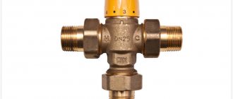
Features of three-way safety valves
Three-way safety valves for heating design are used in heating systems with low circuit temperatures.
The design provides for the presence of three holes, where one is inlet and the other two are outlet. Internal flows are regulated by a valve in the form of a ball or rod, and the distribution of liquid is carried out by rotations.
The valve is responsible for ensuring that all areas of the circuit are demarcated, the flow density is evenly distributed across all zones, and the temperature is normalized.
Three-way valve
If you have a heated floor system, you cannot let too hot a flow flow along the floor circuit; you will need to mix it with cooled liquid, which is ensured by a three-pass model.
The work takes place under the control of a temperature sensor, which is placed in a low-temperature circuit. Then, in the event of deviations, the shutter mechanism is activated, allowing in or limiting the exit of liquid from the return pipes.
Installation rules, replacement frequency
An emergency valve is always installed on the supply side, after the boiler. In this case, the following rules are observed:
- If the relief valve is installed separately, a pressure gauge is placed in front of it to monitor the condition of the system.
- Placed at a distance of 20-30 cm from the boiler.
- The outlet is made with a pipe of the same diameter as the supply pipeline. To determine the pressure as accurately as possible, it may have a slight slope towards the boiler.
- Shut-off devices (taps, check valves, etc.) must not be installed between the boiler and the blast valve.
- In systems with natural circulation, this device is placed at the highest point of the system.
Placed close to the boiler (in many models it is located in the boiler itself, in some boilers there is space for installation)
To prevent the discharged coolant from leaking onto the floor, you can put a hose on the outlet pipe. It can be placed in a container or discharged into the sewer. But in this case, it is necessary to somehow monitor the operation - set an alarm. After all, he doesn’t just play off, but for some reason.
Another important point: after several operations (5-6), the excess pressure relief valve must be replaced. This is due to spring wear. The device starts to work incorrectly. The valve costs a little, so it’s not expensive. The only unpleasant point is that locking devices cannot be placed in front of it. Therefore, the emergency valve can only be removed by completely stopping the system and reducing the pressure to atmospheric pressure. That's the rub.
Where to install the overpressure relief valve
The situation can be improved if shut-off valves are placed after the demolition man. In this case, at least you won’t have to drain the coolant from the system, but only from the boiler, which is not so scary.
Principle of operation
In addition to the main structure, a safety valve for a water heater consists of several more elements. They are housed in a brass or nickel housing. In most cases, the device looks like an inverted letter T. A check valve is attached to the bottom of the tank on the water heater, which can prevent liquid from flowing out of the tank when the pressure in the pipes drops.
The perpendicular branch contains another valve, which is activated after the pressure increases and discharges excess liquid through the fitting. The operation principle occurs in several stages.
- If the tank pressure is lower than that occurring in the pipes, when filling or opening the tap, the poppet plate in the check valve is pressed out by the water pressure. When the pressure level returns to normal, a spring mechanism presses the plate against the protrusion of the housing, limiting the flow of liquid.
- During active heating, the temperature of the liquid slowly increases, and at the same time the pressure increases. Until it reaches the maximum value, the mechanism is not activated.
- After reaching the limit level, the pressure compresses the fuse spring, opening the outlet channel of the fitting. Excessive volume of liquid from the reservoir is removed through this channel. After the pressure drops to the normal level, the spring closes the flow and water removal stops.
Based on the above, it can be understood that liquid will periodically drain from the fitting channel. This phenomenon occurs when water is heated and pressure in the water supply system decreases. If you regularly notice water at the fitting, this means that the safety valve for the boiler is working normally.
However, at the same time there is a need to drain the flowing liquid. To carry out the procedure, a tube of a suitable size is attached to the nozzle: it must be tightened with a clamp to ensure reliable fastening. The standard operating pressure in the water heater tank is from six to ten bar. Without reliable fastening, the tube will simply break off, so the choice of clamp must be approached with special care. Tighten it tightly and lead the tube to the nearest sewer drain.
Valve operating principle
Purpose of the gas valve
PSK is a safety valve element responsible for the safety of the gas pipeline and gas equipment connected to it. During operation, the valve is in a closed position, therefore it is classified as a closed pipe fitting.
Such devices are installed not only on gas pipelines, they are an integral part of other communications - water supply, heating networks. Everywhere they perform the same function - they stabilize the pressure in the network, provide the operating parameters necessary for the proper functioning of the system.
The valve serves to relieve excess gas if pressure parameters become critical. Fuel that creates an imbalance in the system is discharged into an auxiliary pipeline or discharged into the atmosphere
The pressure surge is usually short-lived and depends on a number of factors.
Reasons that can cause excess pressure in the system:
- breakdown of connected gas equipment - double-circuit boiler, instantaneous water heater or capacitive boiler, shut-off valves;
- use of fuel of inappropriate composition;
- change in temperature indicators in the pipeline;
- failure in the thermal-mechanical circuit.
The installation location of the gas safety valve is standard, depending on the efficiency of the application: either in the pressure regulator, or immediately behind it. After automatic operation of the valve, it returns to its operating – closed state.
In a gas network, the valve is a separate device or integrated into the pressure regulator. It is triggered if the operating gas pressure exceeds the nominal level by 15%
What are the consequences of the absence of a PSK on the network? The most common consequences are mechanical destruction of the pipeline or breakdown of connected equipment, which can cause a gas leak.
There is also a possibility of an explosion, so it is necessary to constantly monitor the serviceability of the device, carry out timely maintenance and replace failed elements
Along with relief devices, gas safety shut-off valves are also used, with the help of which the fuel supply is shut off. This happens automatically. The shut-off valve element is installed on the pipeline, in the gap between the filter and the pressure regulator.
The operating limit of the SPD is indicated in the technical data sheet of the device. The upper critical parameter is usually equal to the formula: slave. pressure +25%.
Design and principle of operation of the valve
Valve design
Safety valve design:
- protective cover;
- outlet;
- fillings;
- compression springs;
- cone;
- saddles;
- pressure chamber.
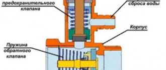
The body is made using hot stamping technology, usually brass is used, and therefore has a long service life. The control unit is made of heat-resistant plastic and does not change its shape. There are different types of safety valves, but the principle of operation is the same. The saddle is acted upon by a spring mechanism and is in the closed state. If the pressure in the pipeline is stronger than the force of the compression spring, the seat will open and the coolant will be released.
Professional installation advice
Even such a simple procedure as installing shut-off valves is based on the implementation of certain rules. For example, the design of a room often requires camouflage of the pipeline and security group.
You can hide devices, but subject to three conditions:
- the length of the flexible line or pipe from the fuse to the tank should not exceed 2 m, otherwise there will be excessive additional pressure on the valve spring;
- the ideal installation of the fuse is directly to the boiler fitting, and if this does not work, then installing a tee is still excluded;
- To service the fittings, a technical hatch should be equipped.
Many people worry when they see drops of water on the valve connection. This is a normal phenomenon and indicates that the device is working properly.
From time to time, small pressure surges occur in the line, which provoke a minimal discharge of liquid. You need to worry when water either does not appear at all or pours continuously.
The line length between the water heater and the fuse should be minimal. This is necessary not for aesthetic reasons, but so as not to create additional pressure in the pipes
It should be remembered that independent modernization of safety devices is strictly prohibited. If you need a 0.8 MPa valve, then you need to purchase just such a new product, and not try to somehow remake or adjust the 0.7 MPa device.
If there is any doubt about the functionality of the safety valve, you should dismantle it and check whether the spring or seal is clogged. Are you having problems with your water heater itself and don’t know what to do? We recommend that you familiarize yourself with common boiler breakdowns and repairs. If you lack skills, invite a specialist from the service center.
How to install a valve on a water heater
Select the desired model
As a rule, good boilers are delivered to the consumer equipped with a safety valve of the required parameter.
If not, or if replacement is necessary, you will have to buy it yourself. They are inexpensive, 250-400 rubles depending on the model.
If there are no special problems with the threaded part (almost all valves have a ½-inch thread), then the operating pressure of the valve is the value to which special attention is paid. The required pressure value must be clarified in the operating manual of your heater.
The required pressure value must be clarified in the operating manual for your heater.
If you purchase a valve with a lower pressure rating, it will constantly leak. If you select a value greater than the permissible value, the valve may not save you from big troubles when the boiler overheats.
How to install correctly
- Before installing a safety valve for a boiler, the device itself must be turned off and the water drained from it.
- The valve is installed at the cold water inlet to the heater.
The process is simple - the usual “packing” with a key for 3-4 turns using sealants (fum tape or tow, as you like). The second threaded end of the valve connects to the cold water supply system. Be sure to check the direction of the incoming water - it is marked with an arrow on the valve body. - If the pressure in the water supply is not stable, or is excessively increased, it would be better to install a water reducer upstream of the valve.
- Not everyone likes the fact that water starts leaking from the valve from time to time. This is a completely normal phenomenon, indicating that the device copes with its intended task. It would be reasonable to connect the drainage pipe with a flexible hose to the sewer system. The hose must be transparent so that the performance of the valve can be visually assessed.
Sometimes attempts are made to hide the valve out of sight by placing it away from the heater. This approach is also possible, but subject to two conditions:
- It is strictly forbidden to install shut-off devices between the valve and the boiler inlet.
- A long vertical section of water supply will itself increase the pressure on the valve, and completely unnecessary “idle” leakage may begin. In any case, there should be no more than 2 meters between the valve and the boiler.
What should you do if too much water flows through the drainage pipe, even without heating up much?
It is possible that the pressure in the water supply is too high (although this is extremely rare) - in this case, installing a reducer will help.
You should also check to see if you purchased a valve with a pressure reading that is too low and does not match the heater model. If everything is normal here, it means the valve spring is “hooked” and it should be changed.
What should be of greater concern is that the valve is always dry under all circumstances.
If, even at maximum heating, not even a drop of water has ever appeared from it, with a high degree of probability we can talk about its malfunction, clogging or jamming. It's better not to risk it and buy a new one.
The simple installation of this absolutely inexpensive device will protect the life and health of the home owners, preserve their property, and extend the trouble-free operation of the water heater.
Safety valve
The name of the device speaks for itself. Its main function is to relieve unexpected loads that may arise under certain circumstances. Plus additionally adjustable coolant flow.
By the way, it can be installed on any section of the pipeline
In this case, it is not the location that is important, but the ease of maintenance if such a need suddenly arises
Types of safety valves
- The simplest option is clutch fuses made of brass. Their design is simple - threads are cut on both sides, and the valve is a spring-loaded rod with an EPDM gasket. This is a direct-flow model, the valve of which opens under the pressure of the coolant flow. Back pressure is blocking the line. This is one of the cheapest devices, but it lasts a very long time, which is time-tested.
- There is another brass option, but with a more complex design, where the pipes are connected in perpendicular planes. It uses a stainless steel rod and spring. Install it directly after the circulation pump. The operating principle of such a device is quite simple. The coolant pressure compresses the spring, which begins to put pressure on the rod. It opens a channel through which the coolant is squeezed out of the system, saving it from ruptures of pipes and other elements. By the way, the maximum temperature that the valve can withstand is 120C.
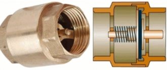
- There are a large number of varieties of check valves, which are also included in the safety group. Their main function is to prevent a counterflow of coolant from occurring if the pressure in the system suddenly drops.
There are several main types - disk, ball, flag and others. But they are all divided into spring-loaded and springless. With the first, everything is clear - there the main emphasis is on the counterforce of the spring. The second type is when the locking element returns under the influence of its own mass.
Three way valves. This type of shut-off valve is installed in heating systems where low-temperature circuits are provided. For example, when the circuit has a condensing boiler. Currently, manufacturers produce this type of valve with manual switching or electric switching. In the second case, it is necessary to connect the device to an alternating current network with a voltage of 220 volts.
Design
A typical safety valve for a boiler has a collapsible design and consists of the following main elements:
Frame . Usually made of brass and shaped like a tee. On its sides there is a lower inlet threaded hole, a side outlet pipe and an upper seat on which the shaped seal is seated.
Locking group . It is a spring-loaded pulley with a cylindrical (disc) end locking element, onto which an elastic rubber seal in the form of a cup (disc) is placed.
Lid . A black cap made of heat-resistant polymer is screwed into the upper threaded pipe of the brass body, holding the spring-loaded rod in the working position. On the upper edges of the lid there are protrusions along which the upper cap, shaped at the bottom, slides, connected to the locking rod. When turned to a certain angle, the cap rises along with the rod and opens the side pipe - this allows you to use the safety valve for heating always open in manual mode.
Cap. The polymer part is usually red in color with a ribbed side surface, and is screwed to the hollow inside of the rod with a screw. The gentle protrusions at the bottom of the cap, when rotated, fall on the teeth of the lid - the handle rises along with the spring-loaded shutter and opens the side channel, allowing you to relieve pressure manually.
Adjusting washer . The inner wall of the cover has a thread in which the adjustment nut rotates; when lowered down, it compresses the spring - thus increasing the valve response threshold. When the nut is unscrewed upward, the spring weakens and the actuation pressure decreases. For turning, the nut is equipped with a transverse slot in the upper part for a flat-head screwdriver.
Valve for water heating boilers - design and appearance
Determination of the conditional cross section and response threshold
It is easy to determine the cross-section of the emergency valve - it must be no less than the diameter of the supply pipe. Otherwise, it will not work as it should. When installing not as part of a safety group, we make the tap with a slight slope towards the boiler (it can be vertical, but definitely not in the opposite direction). If your wiring is inch, we use the same pipe to make an outlet, and install a blast valve of the same cross-section. This is understandable.
Can be part of a security group or installed separately
The response threshold is determined based on the operating pressure of the system. For normal operation it should be 20-30% higher. If your heating operates at 1.2 Bar, then the excess pressure relief valve should operate at 1.45-1.55 Bar.
It is not always possible to find an emergency valve with the required response value. You can either take one with similar parameters, or find an adjustable one (there is one for 1.5 Bar).
Selection of emergency valves
When designing a water supply, heating system or process installation, it is necessary to clearly define the maximum pressure values permissible for its components or network sections. This takes into account such parameters as:
- boiler or main pump performance;
- volume and operating temperature of the working environment;
- features of its circulation.
Based on this, the type, cross-section, capacity, threshold response value, response speed and time to return to its original state, as well as the number and installation locations of safety valves are determined.
In domestic heating systems, spring valves are most often used. For liquid media, low or medium lift devices are sufficient. The throughput should provide a quick pressure release to acceptable values.
The design of the housing is determined by the location where the excess amount of working fluid is discharged. If it will be discharged directly into the environment, an open type valve is sufficient. If the discharge must occur into the drain, a housing with an outlet pipe of the appropriate type of connection will be required. Most often they use threaded or nipple.
Under no circumstances should you purchase a valve with a response threshold that is too high relative to the design threshold. Such a device will not open at the right time. This can lead to equipment damage or even complete system failure.
