Everyone knows that the operation of a heating system, so to speak, by definition is associated with high temperatures of water or other coolant liquid. It is enough to have elementary concepts in thermodynamics to imagine that heating a liquid in some closed volume will cause a significant increase in pressure. This turns out to be a rather unsafe system, for the operation of which it is necessary to provide some kind of protective devices.
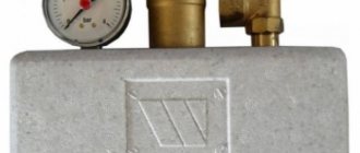
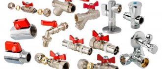
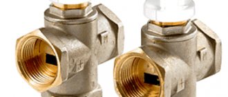
Safety valve in the heating system
The safety valve in the heating system is precisely such a device that ensures the safe operation of boiler equipment. You will not find it in apartments connected to the central system - in fact, it is not needed there, since the temperature and water pressure are adjusted at the elevator units of the general heating points. But for owners of houses or even apartments with an autonomous system, there is no way without this valve.
Therefore, let's take a closer look at this small but very important component of the heating system.
What is it and what is it for?
This device is a special type of safety valve installed in pipeline systems to protect against destruction that occurs when there is excess pressure in them.
Externally, it does not differ from bypass valves, which maintain constant pressure in the system by continuously removing excess fluid. But unlike them, it is triggered in the system periodically, only when the pressure rises above the established norm.
Nuances of proper installation
During the installation of shut-off valves, several rules should be strictly followed:
- The valve is installed strictly in the direction of coolant flow. To avoid mistakes, the product body must be marked with an arrow indicating the working direction.
- Paronite gaskets can be used to seal connections, provided that they do not reduce the diameter of the passage hole. Otherwise, the valve will exert more hydraulic pressure than intended.
- The device must be installed so that other elements of the heating system do not exert additional pressure on its body.
- It is highly advisable to install a mesh in front of the check valve for rough cleaning. This will make it possible to prevent solid particles from entering the locking mechanism, which, in turn, can lead to a violation of the tightness of the device when closed.
Another important point: before installation, you need to once again make sure that the valve is selected correctly.
For example, for schemes with forced circulation, any type of device is suitable, but for gravitational systems, only a rotary petal device without a spring. Since the coolant moving by gravity will not be able to cope with the resistance of the spring.
Purpose and scope of application
The valve is used to protect premises and equipment from excess pressure of the medium transported through pipes:
- heating systems - to remove excess coolant volume from heating devices resulting from thermal expansion;
- water supply - to reduce the risk of water hammer;
- ventilation - ensures air movement only in a given direction;
- gas supply, compressed air supply, fire extinguishing and other types of pipeline structures - in case of emergency situations.
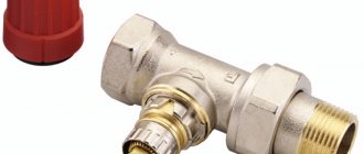
Where to mount and why
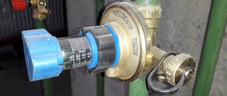
The thermostatic valve is mounted by inserting it into the system at a short distance from the liquid supply pump, between the return and supply circuit.
The mode for setting the maximum permissible pressure limit of the working medium allows the owner to make the settings manually. Currently, the range of these products offered by the retail chain is quite large.
But as practice shows, it is better to pay attention to such well-known brands as Mankenberg, Valtec, DANFOSS. They have proven in practice efficiency, reliability and durability in operation.
Purpose
Regulating thermostatic bypass valves are designed to ensure a stable pressure difference between the return and supply pipelines in closed heating systems. When the heat load decreases, the thermostatic radiator valves close. This leads to an increase in the pressure drop between the return and supply pipelines.
Using a bypass valve offers the following advantages:
- reduces the load on the pump;
- protects the boiler from rust;
- prevents the occurrence of noise unnatural for normal operation;
- increases the temperature of the working medium in the return pipeline.
By closing the thermostatic valves on the radiators, we will increase the resistance of our heating system (increase in the pressure difference between the return and supply pipelines). This will increase the load on the pump and lead to noise.
If the pressure reaches the maximum level, which corresponds to the settings of the bypass valve, it opens, forming an adjustable bypass. Also, a bypass valve is installed behind the circulation pump between the return and supply pipelines.
Controls and technical characteristics
The simplest models of low-flow blast valves, used mainly for domestic engineering systems, are manually controlled mechanically. Products installed on large-section production pipelines can be controlled remotely.
Depending on the material of manufacture and design features, the devices are endowed with different technical characteristics.
The characteristics of several models of emergency pressure relief valves designed to work with gaseous substances are presented in the table.
Connection type
Based on the type of connection or connection to the pipeline, valves are divided into:
- flanged products - equipped with flange plates at each outlet and connected to mating flanges at the ends of the pipes using bolts;
- threaded - imply the presence of outlet pipes with external threads;
- welded - attached to the gas pipeline by welding and ensure 100% tightness.
Recommendations for use
When operating the air pressure relief valve, follow the instructions in the manufacturer's user manual.
The valve must be kept clean and must not be exposed to dust, moisture or other contaminants. It is also unacceptable to paint the valve with a brush or spray gun. This can lead to contamination of the outlet pipe and failure of the device.
Periodically, at least once a month, the valve should be tested for maximum pressure. If for any reason the valve does not operate during testing, operation of the unit should be stopped until the problems are clarified and eliminated.
Such tests should also be carried out after any removal of the valve from the unit, even if the dismantling was not associated with its repair or replacement.
Device
The standard design of an overpressure relief valve includes:
- cast body made of stainless steel, brass or bronze;
- plate - the main shut-off element that blocks the flow of the medium;
- plate lever - used to control this part;
- safety lever - performs protective functions if the main locking element does not work;
- tuning knob;
- springs;
- additional details (control buttons, counters, dials, barometer, etc.).
Types and designs
Relief valves are divided into two main groups:
- direct action, opening only under the influence of pressure from the internal environment. These include devices used to prevent excessive pressure build-up in oil and fuel systems;
- indirect acting, using an external pressure source. They are more suitable for liquid and air systems.
Depending on the design features and principle of operation, they are divided into four types.
With remote sensor
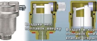
The device is equipped with a spring mechanism and a rod driven by main or backup bellows. When the water overheats, they are affected by a heat-sensitive liquid rising through the capillary tube from the sensor flask.
When the device is triggered, the rod opens the plate for the movement of coolant. There are two pipes in the valve body to the supply line and to the sewerage system to discharge excess water.
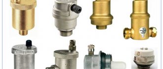
Combined with make-up systems
They are a type of safety valve in heating systems that can perform 3 functions at once:
- dump overheated coolant from the boiler tank based on a signal from an external sensor;
- effectively cool the heat generator;
- automatically recharge the heating system with cold water.
The rod of such a product is equipped with two plates that can simultaneously open 2 passages: one for discharging boiling coolant, the other for supplying cold water.
The models presented in the next photo have a triple output. They are built into the pipeline in front of the heating device or boiler. The lower pipe is used to discharge the medium; two upper pipes are used to connect the water supply and make-up lines.
Spring
In such devices, the spool is driven by the compression force of the working spring. The settings of the same valve can be adjusted by replacing different types of springs included in its kit.
A number of models have an additional lever built into the body that performs manual detonation. With its help, you can manually purge the valve to check its general technical condition or release part of the working fluid.
Since the spring in most cases is exposed to the internal working environment, for devices that work with aggressive substances, it is covered with a protective layer of polymer. Such product models have stem seals like a stuffing box or bellows device.
Lever-load
The main unit of this type of valve mechanism is a lever with a weight suspended on it. The operation of the device is affected by the weight of the load and the length of the lever arm to the place where it is placed. The more massive it is and the farther it is from the rod, the higher the pressure the relief valve is triggered.
To ensure complete sealing of large seats, it will be necessary to use a heavier load, and this can lead to quite a high level of vibration of the entire device. In such cases, valves are used in which the medium discharge cross-section is formed by two parallel seats. The body of such a device also contains two shutters that operate in parallel. This design reduces the weight of the weighting material and the length of the levers and has a positive effect on increasing the rate of operation of the unit.
Design features and operation
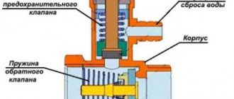
Consider in detail how a safety valve with a spring works. Its body is made using hot stamping technology from brass. The main working element is a spring, which presses the membrane that covers the seat.
Valve with spring mechanism
On the rod connected to the handle there is a washer that serves as a stop for the upper end of the spring. Using the handle, the position of the washer and, accordingly, the clamping force on the membrane are changed. The spring is made of steel; the handle, seals and membrane are made of polymer materials.
The operating principle of the device is as follows: as long as the parameters of the coolant do not exceed the specified maximum permissible values, the membrane tightly closes the hole. When the situation is close to an emergency, as the pressure increases, the superheated coolant (a mixture of water and steam) lifts the membrane, overcoming the resistance of the spring. Thanks to this, the steam-water mixture is discharged out through a special hole. After dumping the excess volume of the steam-water mixture, the pressure in the pipeline decreases, and the coolant again loses the ability to compress the spring.
Note! The device can operate cyclically if the boiler is operated at maximum power, heating the coolant to 90-95 degrees. This mode of operation has a negative impact on the protective device - after several operations the blast valve begins to leak due to loss of tightness.
Advantages and disadvantages
The use of excess pressure relief valves allows you to extend the service life of pipelines by eliminating the occurrence of water hammer and releasing pressure in the system when it increases to critical values. The advantage of these devices is also:
- simplicity and reliability of design;
- easy installation and further maintenance of the device;
- low local resistance values;
- high throughput.
The disadvantages include:
- low wear resistance of sealing gaskets that ensure tightness on the rod;
- unsuitable for working with media containing solid particles.
Types of overpressure relief valves
Based on the method of pressing the locking element to the seat, the devices are divided into the following types:
- Spring. The force of elastic deformation of the spring metal keeps the shutter closed. It is selected in such a way that a pressure exceeding a given level pushes the locking element away from the seat. Spring models are available with both constant response pressure and the ability to adjust it. To do this, an adjusting screw is added to the design, which pre-compresses or weakens the spring. During operation, the spring gradually loses its elasticity, and the response value may change.
- Lever cargo. For pressing, the force of gravity is used, acting on a load suspended at the end of the lever. Such a system has wide possibilities for adjusting the response value. To increase it, the load is moved to the end of the lever, to decrease it, closer to the body. In addition to the possibilities for precise adjustment, this design has another advantage: the stability of the release pressure over long periods of time. Lever devices are characterized by large dimensions and weight. They are used as a safety valve for high-capacity compressors installed permanently.
- Electromagnetic. These advanced devices use an electromagnetic solenoid actuator to press the locking element. Such devices operate as an executive element of a centralized automated control system. The pressure sensor can be located next to the valve, or it can be located in a completely different part of the system. Most of them are equipped with an additional working spring. If there is a loss of power or communication with the control system, the relief valve turns into a regular mechanical one.
According to the method of connection, the relief valves are divided into the following types:
- Threaded. The most common type for low pressure relief devices. Easy to install and dismantle even for untrained personnel - a wrench is enough for this. Most often used as an emergency valve for a low-power mobile compressor.
- Flanged. More difficult to install and more expensive, they provide high tightness. used in medium and high pressure systems.
- Welded. Provide maximum tightness and reliability. Difficult to install/dismantle; special equipment and trained personnel are required.
Based on the material from which the device is made, there are:
- Steel. They have high strength and long service life. Withstands great pressure.
- Brass. They are characterized by high corrosion resistance and long service life.
- Plastic. Cheap, but designed for low pressure values.
Tips for choosing
When choosing a device, you need to focus on:
- its compliance with the maximum permissible pressure in the system;
- pipeline section;
- ambient temperature;
- throughput and height to which the spool is capable of rising;
- type of working substance.
If it is intended to discharge the working medium directly into the air, then a valve with an open type design can be used. For liquid systems, you will need a closed type device, preferably with a special spout for connecting the discharge water drainage hose. The product body must be marked with the direction of the medium flow, which will significantly facilitate installation work.
How to choose a safety valve
The main criterion for choosing a safety device is the technical parameters of the heating system specified in the design documentation.
Most modern closed heating systems use standard direct acting brass safety valves.
They are suitable for installation in systems operating on diesel, gas or electric boilers. When a critical temperature and pressure is reached, the safety valve almost instantly stops further heating of the working environment and prevents an accident.
Simple brass safety valves are designed to exceed the pressure of the working medium up to 3-6 bar.
When choosing a valve for diesel, gas and electric boilers, you need to select safety devices that can withstand pressure 20-25% higher than the normal operating pressure in the system.
For solid fuel boilers operating on peat, briquettes or coal, you need to choose the type of waste dumps more carefully, because solid fuel cannot stop burning instantly and continues to heat water for some time after switching off.
They are suitable for modern thermal relief valves with a maximum operating pressure of 10 bar. The same applies to solid fuel boilers in open heating systems, in which relief valves work most effectively by responding to an increase in operating temperature rather than pressure.
Important! When choosing a safety device, be sure to study the technical documentation for the boiler equipment. Manufacturers usually specify the required maximum pressure and temperature specifications for which relief valves are purchased.
It is not advisable to choose cheap engineering equipment from Chinese manufacturers: it is usually not of high quality and quickly breaks down. An indicator of wear is an increase in the number of valve operations.
We recommend that you read: How to make a table from a metal profile pipe with your own hands
Rules for installation and operation of the device
Installation of the product on the pipeline must be done with sealing gaskets without distortions. The working substance passing through the valve must be free of mechanical inclusions and abrasive particles. It is advisable to install a mesh filter of the appropriate diameter at the inlet to the system. Installation of the device with a spring mechanism is carried out strictly in a vertical position, with the lid facing up. For the lever included in the design of the lever-load device, it is necessary to ensure a horizontal position. It is not recommended to place shut-off elements in the form of taps, gate valves, or levers in front of a relief valve.
To eliminate excess liquid, it is necessary to install an additional outlet used to drain water into the sewer pipeline or return pipe.
If the system includes a gravity device, the valve must be installed at the highest point.
During operation, it is necessary to periodically inspect the device, since in products with a spring mechanism, displacement of the plate towards the walls of the housing may occur.
Required tools and materials
To install the valve you will need:
- adjustable wrench;
- fum - ribbon or tow;
- special paste for sealing joints.
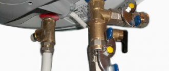
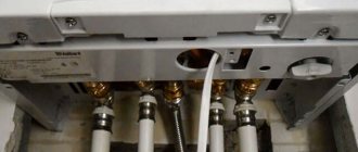
Connection diagram
For example, let's look at the installation diagram of the device in front of the hot water heater in the apartment.
Work progress
Each product designed for releasing excess pressure is equipped with installation instructions, which should be carefully studied before starting work. Before installation, you also need to disconnect the water heater from the network and drain the water from it. The valve must be placed on the cold water supply up to the shut-off valve. The valve installation sequence is as follows:
- marking the installation site;
- removing a part of the pipe of a size corresponding to the length of the device body;
- threading the ends of pipes:
- covering the threaded part with tow or fum tape;
- screwing the valve onto the pipe thread;
- connecting to another pipe a pipe leading to the sewer system.
- tightening the threaded connection using an adjustable wrench;
- sealing the joint with a special paste;
- setting up the device in accordance with the passport values (if necessary).
Installation Rules
In closed heating systems, the safety valve is installed at the highest point of the supply circuit.
There should not be any functional elements (valves, valves, gate valves) between it and the boiler. A mandatory requirement for installing the device is a strictly vertical position. Installation even at a slight angle will result in water leakage.
A discharge hose is connected to the valve's discharge pipe, which is directed into the sewer. It is advisable to choose a location for installing the device to ensure easy access to it in case of need for maintenance or replacement.
Expert advice
- A blasting device with standard technical characteristics allows water to pass through even at low pressure levels when clogged. The problem can be solved by cleaning the body parts. To do this, the product must be dismantled and placed in a container with vinegar for 2 - 3 hours. Then rinse it with water until completely clean and install it in its original place, lubricating the connection area with alcohol.
- If the valve continues to leak even after cleaning, then most likely the rubber gasket resting on the seat is clogged with debris. It is easier to replace such a part than to clean it without deformation. Replacing the valve on the supply pipeline to the boiler can be seen in the video:
- A number of consumers quite reasonably doubt the durability of shut-off valves with plastic parts. They actually have a shorter service life, so it’s better to immediately buy ones with metal components. Such products are on average 100 - 150 rubles more expensive, but they last much longer.
- You cannot simply turn off the device, even if it is leaking. A huge number of heating boilers have failed precisely after installing the plug.
Why is the emergency valve leaking?
If a puddle appears under the safety valve, it is necessary to inspect the system. If you do not pay attention to this symptom for a long time, the boiler may even explode. So let’s immediately check the possible reasons:
- The pressure in the expansion tank is too low and it cannot cope with the task. Check the pressure in the membrane tank. To do this, there is a spool in the upper part; we connect a pressure gauge to it and look at the readings. It should be 0.2-0.5 bar less than the operating pressure of the system. If it’s too low, take a pump and pump it up through the same spool.
- The membrane in the membrane tank is damaged. The solution is to change the membrane or install a new tank.
- The membrane tank is smaller than required for the system (10% of the system volume). If the volume is really small, we either install a second tank or change it to a larger one.
- The coolant overheats (boils). To solve the problem, circuit solutions are required; circuit modernization is required. A more gentle but temporary solution is to reduce the intensity of combustion.
If you do not pay attention to the dripping blast valve, the boiler may burst - The emergency valve is clogged. Sometimes deposits appear on the seat or rubber gasket. This could be debris brought in by the flow of coolant, or it could be the result of constant leaks. In the first option, we simply remove the debris and put the device in place. In the second case, the valve will have to be replaced. Plaque forms when a little fluid is released and it dries out, and this is abnormal operation of the system (or valve). The solution is replacement. If the new one is leaking, you need to check all the options in the list above.
- Incorrectly set actuation pressure on the valve. In this case, you need to check at what pressure your safety device actually operates. To do this, by lowering and increasing the pressure in the system, you can determine the real response threshold. If the model is adjustable, adjust the settings. If the response value is fixed, you will have to buy another device.
Once again, we draw your attention to the fact that a puddle under the emergency valve is a cause for concern and a signal that it is necessary to inspect the system components responsible for stabilizing the pressure.