Combustion devices
Combustion devices
Combustion devices are one of the main elements of a boiler unit. A combustion process occurs in it, during which the chemical energy of the fuel is converted into thermal energy of combustion products, which is then transferred to the liquid and steam located in the boiler.
Existing combustion devices can be divided into layer and chamber. Layer fireboxes are designed to burn solid fuel in a layer on a grate. In chamber furnaces, solid fuel is burned in suspension in the form of dust and crushed particles, as well as liquid fuel sprayed using nozzles and gaseous fuel. Chamber furnaces are divided into flare and vortex (cyclone).
In Fig. Figure 19.1 shows diagrams of layer, flare and vortex methods of fuel combustion. With the layer combustion method, the air necessary for combustion is supplied to the fuel layer through the grate.
With the torch combustion method, solid fuel is pre-ground in mills and dust along with air (air mixture) is fed into the furnace. The residence time of gas and dust in the furnace volume is insignificant (1.5 - 2 s). Therefore, depending on the type of solid fuel, the grinding fineness (i.e., the percentage by weight of particles of certain sizes) is selected differently. For example, when burning anthracite and lean coals, only 7 - 15% by weight should be particles larger than 90 microns, bituminous coals - 15 - 35%, and when burning brown coals for such particles it can be already 40%.
A decrease in the size of fuel particles leads to an increase in the specific surface area of contact with the oxidizer. A high temperature develops in a burning dust-air torch. This helps to intensify fuel heating and ignition.
The cyclonic combustion method is based on the use of swirling fuel-air flows. Fuel transport is carried out by air. Fuel particles circulate along specific trajectories for the time required to complete their combustion. Under the influence of centrifugal forces, the particles move in the form of a compacted wall layer, intensively mixing with air. The residence time of particles in the cyclone chamber is selected sufficient to burn out coarse dust (particle size 200 microns) or crushed fuel (particle size up to 5 mm).
Layer fireboxes. According to the method of mechanization of maintenance operations (fuel supply, layer drilling, removal of ash and slag), layer furnaces are divided into manual (non-mechanized), semi-mechanical and mechanical. In semi-mechanical furnaces, part of the operations is mechanized. In mechanical fireboxes, all operations are mechanized.
The classification of the most typical and relatively widespread combustion devices with layered combustion of fuel is shown in Fig. 19.2.
Depending on the method of organizing the fuel combustion process, layered furnaces can be divided into three groups:
- with a fixed grate and a fixed layer of fuel (Fig. 19.2, a, b);
- with a fixed grate and fuel movement along the grate (Fig. 19.2, c, d, e);
- with a movable grate and a layer of fuel moving with it (Fig. 19.2, e).
In shown in Fig. 19.2, and the firebox is loaded with fuel manually and focal residues are manually removed through the ash pan. Due to the high cost of physical labor, fireboxes of this type are used only for boilers with low steam output (up to 0.5 kg/s).
In Fig. Figure 19.2, b shows a semi-mechanical firebox with a pneumomechanical thrower (PMZ) (Fig. 19.3) and manual rotating grates (RPK). The fuel is fed by the PMZ feeder and is evenly distributed over the grate. Focal residues are removed by dumping them into the ash hopper when turning the grate around its axis from a manual drive. In the firebox shown in Fig. 19.2, c, loading is carried out under the influence of the fuel’s own weight. Fireboxes with an inclined grate (with an angle of 40 - 45°, which corresponds to the angle of repose of the burned fuel) are usually used for burning wood waste and sod peat. The reciprocating and translational movement of the grate on the inclined-pushing grid (see Fig. 19.2, d) makes it possible to carry out continuous drilling of the fuel layer.
Rice. 19.1. Schemes of solid fuel combustion methods
a - layered; b - flare; c - vortex; 1 - fuel; 2 - air.
Rice. 19.2. Schemes of layered fireboxes
1 - fuel; 2 - air; 3 - combustion products; 4—focal remains. In such fireboxes it is possible to burn oil shale, brown coal with high ash content and high humidity, and hard coal with a high yield of volatile substances.
Combustion devices with a rustling strip of the TShPM furnace (see Fig. 19.2, e) are designed for burning multi-ash brown and non-caking coals. The rustling strip is made in the form of a triangular prism made of cast iron or steel. The angle of inclination of the front plane to the horizontal plane is 35°, and that of the rear plane is 15°. When moving forward (towards the rear wall of the firebox), the fuel is pushed in the same direction. During the reverse stroke, the fuel layer is trimmed by the rear edge and the burning fuel layer is drilled.
In Fig. 19.2, e shows the firebox designed by Prof. Makariev for burning lump fuel with milled peat additive. This firebox is equipped with a pre-furnace in the form of a shaft, in which the fuel is dried and partially gasified. Drying hot air enters through channels located on the front wall of the firebox.
The fuel is supplied to a slowly moving grate of a 6-7 m long chain grate, mounted on two drums. The chain grate is made either with overhead grates or with so-called scaly grates, which ensure operation of the grate with virtually no fuel loss. The moving speed of the grate can reach 30 m/h. In this case, three zones are observed in the layer: fuel drying and release of volatiles, coke combustion and burning of flammable substances from ash and slag.
The air is distributed unevenly over the area of the grate. Less air enters the zone of drying and release of volatiles (for fuels with low 1/g), as well as the zone of combustion of combustibles from slag, than into the coke combustion zone. When burning fuels with a large release of volatiles into the area where they exit, the air supply increases. Fresh fuel is ignited from the radiating arch and from contact with the burning layer nearby. To increase the combustion intensity, air heated to 220 - 250 C is recommended to be supplied under the grate through the blowing sections (see Fig. 19.2, e). The latter is not dangerous for the strength of the grate, since the grate sheet is only half of the time under the layer of fuel, and then makes return idle strokes and at the same time cools.
For the combustion of anthracite, low-caking hard and brown coals with Ap < 25%, combustion devices with a chain grate are equipped with pneumomechanical throwers (Fig. 19.3). The movement of the grate is directed towards the front wall of the firebox (reverse movement).
The combustion process in fireboxes with a chain grate equipped with pneumo-mechanical throwers is of a mixed nature. Large fractions of fuel burn in the layer, and in the space above the layer - dust, which inevitably forms during transportation and preparation of fuel for combustion, as well as volatile substances that are not burned directly in the layer.
To improve combustion and reduce chemical and mechanical incompleteness of combustion, secondary air is introduced into the combustion space using a special fan under a pressure of 3 - 4 kPa (the so-called sharp blast) in an amount of 5 - 10% of the total air flow. The blast air pressure under the grate, which ensures less removal of small fuel particles from the layer, is about 0.5 kPa for coals and 0.8 kPa for anthracites.
Chamber combustion devices for burning solid fuels are used in boiler units of medium (10 - 42 kg/s) and high (> 42 kg/s) productivity.
Rice. 19.3. Pneumo-mechanical fuel spreader
1 - bunker; 2 - feeder; 3 — rotary thrower; 4 - nozzle grille
The main advantages of chamber fireboxes are as follows:
- the possibility of economical use of almost all types of coal, including low-quality ones that are difficult to burn in a layer;
- good mixing of fuel with air, which allows you to work with a slight excess of air;
- the possibility of increasing the unit power of the boiler unit;
- relative ease of regulation of the operating mode and, therefore, the possibility of complete automation of the combustion process.
Pulverized coal combustion structures can be classified according to the location of the burners (front, counter, corner) and the method of removing slag from the chamber (solid or liquid). The location of the burners on the walls of chamber furnaces is shown in Fig. 19.4. Ceiling and single-tier front arrangement of burners is used for boilers with a capacity of up to 33 kg/s (120 t/h). For boiler units with a capacity of over 33 kg/s, lateral counter and angular tangential arrangement of burners is recommended. Multi-tier front installation of burners is also used.
A scheme with the installation of corner tangential burners is preferable, since in this case intense (vortex) mixing of fuel with air is created, higher temperatures develop and the combustion process proceeds more completely.
Depending on the method of removing slag from the combustion chamber, furnaces are used to remove slag in solid and liquid states. In Fig. 19.5, a shows furnaces with removal of solid slag, and in Fig. 19.5, b - liquid slag.
High-ash brown coals, bituminous coals, milled peat, and shale are burned in furnaces that remove solid slags.
It is advisable to burn weakly reactive fuel (anthracite, semi-anthracite, lean coal) in furnaces with the removal of liquid slag.
The walls of chamber fireboxes are covered with screen pipes, which are evaporative heating surfaces. Screen surfaces are the most intensively working parts of the boiler, since they perceive heat through radiation, which, under combustion conditions, is the most effective method of heat transfer. The convective component of the total heat transfer is insignificant due to the low speed of gas movement.
It follows that a unit of screen heating surface area produces significantly more steam than the same unit of heating surface area receiving heat due to convection. This means that boilers with screen fireboxes can provide greater steam production with smaller heating surface areas, and therefore with smaller dimensions, than boilers with unscreened fireboxes (for the same purpose, screens are often installed in fireboxes and with layered combustion of fuel). Increasing the temperature in the combustion chamber is one of the means to reduce the area of heating surfaces located in the combustion chamber (see § 19.2).
Rice. 19.4. Layout of burners in the combustion chamber
a - ceiling; b - frontal; in - counter; g - angular tangential; 1 - primary air and dust; 2 - secondary air.
Naturally, the temperature of the gases at the outlet of the furnace is always lower than the temperature in the combustion zone, since part of the heat is transferred to the screen surfaces. If its value exceeds the softening temperature of the ash, then part of the ash carried away from the furnace, deposited on the walls of the pipes and lining, will prevent further normal operation of the furnace.
It should be noted that large ash carryover is one of the significant disadvantages of pulverized coal furnaces. Carryover reaches 85% and higher. The rest of the ash is deposited in the lower part of the furnace (see Fig. 19.5, a).
The result of large ash carryover is abrasion and corrosion of heating surface pipes (steam superheaters, economizers, air heaters) and smoke exhauster blades, as well as pollution of the surrounding atmosphere, which creates unsanitary conditions in populated areas located near boiler houses. Therefore, recently in powerful boiler units fireboxes with liquid slag removal have become widespread, in which ash carryover is reduced to 50 - 60% (see Fig.; 19.5, b). The principle of constructing such a firebox is that in the lower part of the chamber the screens are covered with refractory material. In this area, the temperature is higher than the temperature of the liquid-melting state of the ash (by 100 °C or more). This gives the liquid slag good fluidity; it flows along the walls of the combustion chamber into the slag bath and then into the slag receiving device, where it is granulated with water. From there the slag is removed to the ash dump. Gases from below move upward and, giving off heat, leave the firebox.
Rice. 19.5. Flare furnaces for burning pulverized fuels
1 - burner; 2, 3, 4 - pipes of the front, side and rear screens, respectively; 5 - bath for liquid slag; 6 - taphole; 7 - slag receiving tank; 8 - cold funnel; I - fuel; II - air; III - combustion products; IV—focal remains.
Before being fed into the firebox, the fuel undergoes preparation: crushing into pieces 10 - 12 mm in size, drying and grinding the pieces in mills to a dust state (less than 200 microns).
The quality of pulverized fuel is usually judged by its fineness and uniformity. The fineness of the dust is characterized by the remainder of its sample after sifting through a set of sieves with opening sizes of 60 - 1000 microns. In general, the finer the grind, the better the fuel is mixed with air and the better the combustion process is, while reducing heat loss due to mechanical underburning of the fuel. But it should be borne in mind that with increasing fineness of dust grinding, the costs of its preparation increase. At a certain fineness of dust grinding, the total costs become minimal.
The fineness of grinding is determined by the type of coal. The main factor determining the economics of dust grinding is the release of volatiles. Fuel with a higher volatile yield burns more intensely, so it can be burned with a coarser grind.
The type of mill is selected depending on the required grinding fineness and hardness of the coal. Ball drum mills (BDM) are used for grinding anthracite and lean hard coals and belong to the class of low-speed mills. The mill is a drum rotating at a frequency of 15 - 25 rpm with a diameter of 2 - 4 and a length of 2.5 - 8 m. The inside of the drum is lined with armor plates, 25 - 35% of the drum volume is filled with steel balls. When the drum rotates, the balls rise to a certain height and fall down. The coal is broken up by the falling balls and is partially abraded as they roll. Mills of this type are the most energy-intensive. Currently, medium-speed mills are often used. The fuel in these mills is crushed by crushing it in a special chute along which balls or rollers move. The rotation speed of the moving part of the mill is 50 - 150 rpm. These mills differ from the ShBM in that they are lighter in weight.
Brown and hard coals with a relatively high volatile yield and low mechanical strength are ground in hammer (high-speed) mills.
In Fig. Figure 19.6 shows a high-speed hammer mill for grinding fuel with a shaft for gravitational dust separation. This firebox is designed for burning brown coal, hard coal (Vr > 30%), milled peat, shale. Fuel is supplied to the mine through chutes 3. Pieces of fuel fall down and are crushed upon impact with hammers mounted on a rotor, which rotates at high speed. Part of the air is supplied through air duct 2. Fine dust is picked up by the air flow and is directed through shaft 4 into the firebox through embrasure 5. The rest of the air is supplied to the firebox through nozzles 6. Larger particles that are not carried away by the air, under the influence of their own weight, fall down the shaft again for further grinding.
Combustion of solid fuel in a flare. The design of the burners used is of great importance for the operation of pulverized coal furnaces. Burners must ensure good mixing of fuel with air, reliable ignition of the air mixture, maximum filling of the combustion chamber with a torch, and be easy to regulate in terms of productivity within specified limits.
Currently, vortex burners with swirling flows of air mixture and secondary air and slotted straight-jet burners are widely used for flaring solid fuels.
In slot burners, the dust-air mixture is fed into the firebox through narrow slits. The range of the torch with such an introduction of the air mixture into the furnace is significant. These burners are used for counter or corner installation in the combustion chamber.
Vortex burners produce a short torch and are installed on the front wall of the combustion chamber.
Various schemes for supplying the air mixture and secondary air to the furnace are shown in Fig. 19.7. In Fig. 19.7, a, b shows options for introducing air mixture and air flows into slotted direct-jet burners. According to the conditions for fuel ignition, supplying the air mixture along the periphery of the burner (see Fig. 19.7, a) is more rational than supplying it through the central channel (see Fig. 19.7, b), since in the latter case the heating of fuel particles before ignition is prevented by the relatively cold (compared to the temperature in the firebox) layer of secondary air.
In Fig. 19.7, c shows a diagram of the supply of air mixture and air to the vortex burner. The dust-air mixture is supplied through the central pipe, and secondary air through the peripheral channel. The installed divider presses the straight-jet flow of the air mixture into the area occupied by the swirling flow of secondary air. The divider is a poorly streamlined body, and behind it a zone is formed where hot combustion products are recirculated, which contributes to stable ignition of the air-fuel mixture and good stabilization of the torch.
In practice, a scheme for supplying the air mixture and secondary air using swirling jets is often used. In this case, there is no need to install a divider, since with such an organization of flow movement, the reliability of ignition and flame stabilization is achieved due to the recirculation of combustion products into the rarefaction zone.
Rice. 19.6. Firebox design with hammer mill.
1 - hammer mill; 2 - air duct to the mill; 3 — flow for fuel supply; 4 - mine separator; 5 — embrasure; 6 - nozzles for the release of secondary air.
Rice. 19.7. Schematic diagrams of burners for burning pulverized solid fuel.
a b - direct-flow burners; c - vortex burner; 1 - secondary air; 2 — air mixture; 3 - recirculation of hot gases.
Rice. 19.8. Schematic diagrams of fuel oil nozzles
1 - fuel; 2 - air; 3 - par.
Combustion of fuel oil and gases in combustion devices. Liquid fuel burned in furnaces is subjected to preliminary atomization using a nozzle, which is an element of the burner. In general, a burner is understood as a unit that includes, in addition to a nozzle, an air guide apparatus, an ignition device and a control mechanism.
High-quality combustion of liquid fuel is determined by the fineness of its atomization. For this purpose, injectors are used, which, in addition, provide the necessary range of fuel consumption control and stable ignition of the mixture.
Depending on the method of fuel atomization, injectors are divided into four classes: mechanical, steam, air (pneumatic) and combined. In Fig. 19.8 shows schematic diagrams of the nozzles used.
Mechanical atomization nozzles can be divided into direct jet, centrifugal and rotary. In straight-jet nozzles (Fig. 19.8, a), the fuel stream is crushed into tiny droplets when it is pressed under significant pressure (1 - 2 MPa) through a small-diameter nozzle.
In centrifugal injectors (Fig. 19.8, b, c), fuel is atomized under the action of centrifugal forces that arise when the fuel flow swirls. The rotational motion of the fuel is imparted by its tangential supply to the vortex chamber of the nozzle (see Fig. 19.8, b) or by a special swirler installed at the outlet of the nozzle (see Fig. 19.8, c).
In rotary nozzles (Fig. 19.8, d), fuel is supplied inside a rapidly rotating atomizing glass, where it spreads under the action of centrifugal forces, forming a thin film. At the outlet edge of the glass, a thin film is picked up by the supplied primary air.
Steam and pneumatic nozzles can be combined into one class - nozzles with atomizing media. In steam nozzles (Fig. 19.8, d), water vapor with a pressure of 0.4 -1.6 MPa is used as such a medium. Fuel oil is supplied to the nozzle under a pressure of 0.3 - 0.4 MPa. The higher the speed of the steam jet, the finer the fuel is atomized. Most nozzles reach a critical steam velocity (see §8.1).
Steam nozzles are simpler in design than mechanical ones, but due to the high steam consumption (0.30 - 0.35 kg of steam per 1 kg of fuel oil) and strong noise, they are used in boilers with a capacity of up to 3.3 kg/s.
Pneumatic nozzles, in which air is the atomizing medium, can be divided into high and low pressure nozzles. The first group includes nozzles in which the air pressure is 0.2 - 1 MPa and higher (see Fig. 19.8, e), the second group includes nozzles in which the air pressure is 0.002 - 0.008 MPa (Fig. 19.8, f ).
In high-pressure nozzles, air for atomization is supplied from the compressor in an amount of 10 - 15% of the total flow. In low-pressure nozzles, air is supplied by a fan, and the amount of it supplied to the spray is 40 - 100% of the total flow rate.
When comparing the advantages of high and low pressure pneumatic nozzles, preference should be given to the latter. Firstly, they provide higher quality of fuel atomization due to high specific air consumption; secondly, more favorable conditions are created for fuel combustion as a result of intensification of the mixture formation process. In addition, low-pressure fuel pumps and fans operate, which leads to a reduction in energy consumption for the electric drive. The disadvantage of low-pressure pneumatic nozzles is their significant dimensions, which increase with their productivity.
In Fig. 19.9, a, b show the designs of centrifugal mechanical and steam nozzles, respectively.
Steam and pneumomechanical nozzles, which belong to the combined class, are also widespread. At nominal (calculated) fuel consumption, combined injectors operate as mechanical injectors, i.e. with high fuel pressure, and at low flow rates - with the supply of an atomizing agent (steam or air). In such injectors, the rotational movement of fuel is created by its tangential supply or using swirlers of various designs. To ensure a finer spray of fuel oil, reduce its viscosity by preheating it. Depending on the brand of fuel oil and the type of nozzle, its heating temperature is assumed to be different. For example, for air injectors the heating temperature of fuel oil grades is 40; 100 and 200 are respectively equal to 363, 380 and 403 K; for mechanical nozzles these temperatures are 376, 388 and 413 K, and for steam nozzles - 348, 371 and 388 K. Heating oil does not require preheating due to its low viscosity even at low temperatures (up to 263 K).
In accordance with the general principles of the theory of combustion of gaseous fuel (see § 18.4), gas burners are:
- complete pre-mixing (gas and air are mixed before exiting the burner) - kinetic;
- partial pre-mixing - diffusion - kinetic;
- external mixing - diffusion.
According to the method of air supply, burners are divided into injection and blown (with forced air supply). In accordance with this, burners of low gas pressure (up to 5 kPa), medium (5 kPa - 0.3 MPa) and high (more than 0.3 MPa) are distinguished. Injection burners are available only in low and medium pressure.
In Fig. Figure 19.10 shows the basic circuit diagrams of gas burners. In an injection burner (Fig. 19.10 a), the gas flowing from the nozzle ejects (sucks in) air and mixes with it. The gas-air mixture in the injection burner burns in a nozzle (tunnel) immediately adjacent to it made of refractory material. Due to the high temperature of the internal surface of the nozzle, combustion of the finished gas-air mixture occurs almost instantly and ends inside the nozzle. For this reason, such burners are conventionally called flameless.
The volume of a combustion chamber adapted for flameless combustion of gas can be significantly reduced, and when choosing the dimensions of the chamber, it is not based on the need to ensure completion of the combustion process in it, but on the condition of obtaining the largest heating surface area.
The gas flow through the burner, depending on its design, can vary widely - from 0.5 to 1000 m3/h and higher. The length of the nozzle reaches 1 m, the speed of the gas-air mixture reaches 30 - 80 m/s. Injection burners are installed under boilers with a steam capacity of less than 2.75 kg/s (10 t/h). An important advantage of burners of this type is the absence of fans for air supply, which reduces energy consumption for servicing the boiler unit.
The diagram of the simplest burner with forced air supply is shown in Fig. 19.10, b. Gas is supplied to the annular space between the inner pipes, and air is supplied to the annular space between the middle and outer pipes, while the design provides for turbulence of gas and air flows. The gas is ignited through the inner pipe, and the operation of the burner is monitored through it. The gas is mixed with air in an expanding embrasure located in the furnace lining.
Rice. 19.9. Oil nozzle.
1, 2 - pipes for steam and fuel oil; 3 - body; 4 — supply barrel with distribution disks; 5 - nozzle; 6 - nozzle.
Rice. 19.10. Burner diagrams for gas combustion.
1 - gas nozzle; 2 - regulating air damper; 3 - mixer; 4 — ceramic nozzle; 5 — blade swirler; 6 - gas manifold; 7 - firebox lining; I - air; II - gas.
The mixing process is significantly improved if the gas is supplied in small jets flowing from small holes (Fig. 19.10, c). The air flow is swirled with a special swirler.
The mixing of gas with air ends within the embrasure.
In addition to purely gas burners, some installations use burners for co-combustion of gas and fuel oil or combined combustion of low-calorie gas with pulverized fuel, etc. The designs of burners used under boilers and in industrial furnaces are described in specialized literature.
For reliable and economical operation of a boiler unit, not only the type of burner is important, but also their number. As a rule, several burners are installed in the furnaces of boiler units. This is necessary so that the torch fills the furnace volume as much as possible and it is possible to regulate the combustion processes in the required range of changes in heat output during variable operating modes of the boiler unit. Each burner type has a limited range of heat output control. By varying the fuel consumption and the excess air coefficient on each burner within acceptable limits, it is possible to achieve a certain depth of regulation and the heat output of the boiler unit.
Technological conditions for firing building products require, in some cases, semi-coking or coking in remote furnaces, i.e. processes that obviously occur with incomplete combustion of fuel as a result of supplying primary air to the furnace in an amount of 50% of the total flow rate required for the combustion of this fuel. The air entering the furnace for combustion of coke (or semi-coke) gas is called secondary. The use of these processes makes it possible to achieve higher and, moreover, evenly distributed temperatures in furnaces and, therefore, better firing due to the partial transfer of the combustion process to the working spaces of the furnaces. To produce gas by semi-coking, fuel with a high yield of volatile substances (firewood, peat, long-flame coals) is usually used, gasified in mine furnaces with a fixed bed of fuel.
In some types of kilns, such as ring kilns, used in the production of clay bricks and tiles, fuel is burned in the working space directly among the fired products (Fig. 19.11). Such stoves do not have remote fireboxes and allow you to burn all types of solid fuel without special preparation. For this purpose, solid fuel is loaded through fuel tubes with a diameter of 150 - 200 mm, under which grates are laid out of raw material, where fuel combustion occurs. When using gaseous fuel, the grates are not laid out and the gas burns in the spaces between the rows of the charge, coming out of the burners located in the hearth and roofs of the furnace. In ring kilns, firing with the pressing of powdered fuel into the raw material is also used to prepare the clay mass. Typically, up to 70% or more of the total amount of fuel required for firing is introduced into the raw material, and the rest is loaded through fuel tubes.
Rice. 11.19. Cross section of a ring furnace.
1 - burning channel, shaped like a ring; 2 - channel for loading raw materials; 3, 7 — valves; 4 - heat channel; 5 – fuel pipes; 6 — connecting channel; 8 - smoke channel.
Rice. 19.12. Schematic diagram of a tunnel kiln.
1 - through channel; 2 — trolleys with fired products; 3 - fan; 4 - zone smoke exhauster; I - heating; II - firing; III - cooling.
Due to the high cost of manual labor in high-temperature conditions, new factories are currently building tunnel-type furnaces instead of ring furnaces (Fig. 19.12), which are long channels (up to 150 m), fenced on the sides with walls, and on top - vault The bottom part of the working part of the furnace is formed by movable trolleys with fired products.
Rice. 19.13. Scheme of a pouring shaft furnace.
M + T - material and fuel; DG - flue gases; Pr - products; To the air; zones: I - heating; II - firing; III - cooling.
Hot gases move towards the trolleys (counterflow principle), and cold air is supplied from the trolley exit side, which cools the fired products, while it itself heats up and is used to burn fuel and partly in dryers. The fuel most often used is gas, solid powdered fuel with most of it pressed into the raw material, as well as lump fuel loaded through the cracks of the roof or burned in remote furnaces.
Rotary and shaft kilns are used for firing binders (lime, cement, gypsum, etc.).
According to the heating method, shaft furnaces are divided into pour-over furnaces with remote fireboxes and gas-heated furnaces. In transfer kilns, solid fuel (anthracite) and the fired material are usually loaded layer by layer in a ratio determined by the characteristics of firing (Fig. 19.13).
Rice. 19.14. General view of a rotary kiln with a diameter of 5 m and a length of 185 m.
1 — feed pipe for supplying sludge; 2 - filter; 3 — ring wheel; 4 - gearbox: 5 - electric motor; into support rollers; 7 - bandage; 8 — cylindrical body; Furnace header for supplying fuel and air.
The disadvantage of these furnaces is that the material becomes clogged with ash. If a shaft furnace has an external combustion chamber, then, as a rule, the process of fuel semi-coking is carried out in it. The resulting gases (CO and H2) at temperatures of 600 - 800 ° C from the furnace are sent to the furnace, where they, reacting with secondary air, burn and give the temperatures necessary for firing - approximately 1200 - 1300 ° C. When using gaseous fuel, air is usually introduced through windows in a hollow column (core) installed in the center of the furnace shaft. This makes it possible to distribute air evenly throughout the entire section of the shaft.
In rotary kilns, the firing zone is stationary, but the material moves. By design, a rotary kiln is a cylindrical drum made of thick sheet steel (up to 40 mm), lined inside with a refractory lining (Fig. 19.14). The drum diameter is 2.5 - 7 m and the length is 200 m or more. The furnace body is located at a slope of about 4° and rotates at a frequency of 0.5 - 1.2 rpm. Pulverized, liquid and gaseous fuels are used as fuel, along with which up to 20 - 30% of primary air is supplied. Secondary air (70 - 80%), having received heat when the material cools in the oven refrigerator, then enters directly into its working space. The material moving in the rotary kiln occupies up to 15% of its live cross-section, and the rest of the space is filled with a gas flow, which, by radiation and convection, transfers heat to the open surfaces of the material and lining.
Melting plants include cupola furnaces (for melting slag and rocks in the production of mineral wool), digesters (for melting organic binders - bitumen, tar, pitch, resin) and bath furnaces (for melting glass). In cupola furnaces, the fuel most often is coke, which produces little ash during combustion and contains few volatile substances. Coke is part of the charge. Unlike a shaft furnace, in the lower part of the cupola the temperature of the material reaches its melting point and the melt flows in streams into the lower part of the furnace.
To improve the distribution of air throughout the furnace volume, it is supplied through two to three rows of tuyeres along the height of the cupola. Currently, coke and gas furnaces and even pure gas cupola furnaces are widely used.
Bulk materials are melted in bathtubs or pot furnaces lined with refractory materials. These furnaces are heated by burning gas or fuel oil, but recently they have begun to use electric heating, and also provide for the development of an installation for melting bulk materials in suspension.
A detailed description of the design of combustion devices and furnaces used in the building materials industry is given in special courses on thermal installations.
Advantages of metal fireboxes
The traditional fireplace, which has been around for centuries, has an open combustion chamber lined with refractory bricks. Heat into the room from such a heating device is supplied only by direct thermal radiation from the hearth, since the brick walls of the fireplace do not have time to warm up properly to become a significant source of heating the room.
The metal firebox built into the brick structure retains heat well inside the fireplace, and also provides a number of advantages that can be determined by studying this diagram:
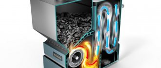
One example of the structure of a metal fireplace insert with an air flow circulation diagram
- It is possible to regulate the burning intensity of the wood stash.
- The smoke does not enter the room, but goes into a metal chimney connected to the firebox.
- Between the outer walls of the metal chimney and the outer casing in which it is enclosed, a space is formed that works on the principle of a convector. Heated air enters the room through windows provided in the casing, equipped with metal grilles, sometimes with controllable blinds.
- The glass of the firebox also heats up and releases heat into the room.
- If desired, you can always open the fire door and sit by the open fire.
- When the firebox is closed, you can also observe the burning of wood, since the glass is not covered with smoke due to the provided airflow.
- Safety. A closed firebox eliminates the risk of coals accidentally entering the room, which often happens when wood burns intensely in a traditional fireplace.
Prices for a fireplace with glass
fireplace with glass
Example of fireplace arrangement
There are a lot of different orders that allow you to lay out fireplaces of very different configurations. However, the technology for carrying out work always includes the same steps, which will be discussed below.
As an example, we will consider making fireplaces with our own hands with the following parameters:
- Portal width – 62 cm;
- Height – 49 cm;
- Firebox depth – 32 cm;
- A square pipe with a side of 26 cm is used as a chimney;
- To lay the back side of the fireplace, half bricks are used, and the side walls are laid out of solid bricks.
Fireplace portal
There are two basic types of portal ceilings - straight and arched. The straight design has the simplest appearance, but its installation is rightfully considered the most difficult. The main problem of arranging a direct floor is the exactingness of calculating the angle of the brick cut and the complexity of its installation.
The fuel tank located below is usually made in the shape of a rectangle or trapezoid. A mouth is formed right above the firebox, into which all the smoke released when the fuel burns goes. To regulate smoke removal, a damper is installed in the front part of the chimney. At the front edge of the mouth there is an overlap, and behind it is a chimney tooth.
Arched portals, depending on their shape, are divided into three categories:
- Semicircular . In such designs, the radius of the arch is exactly half the width of the combustion chamber. Semi-circular portals are considered the most reliable and simple.
- Bulbous . The bending angle of arched arches is slightly less than that of semi-circular arches, so this option is best suited for fireboxes that have a large width. In addition, the beam arch of the portal may well be used in situations where there is a need to limit the height of the combustion chamber.
- Direct.
Fireplace design
When we build brick fireplaces, the first thing we need to do is create a project that displays all the necessary dimensions of the structure and its parameters:
- Creating a drawing . At this stage, a place to install the fireplace is usually selected and its dimensions are calculated. When these parameters are known, fireplaces with a detailed description must be depicted on paper, observing the scale and putting down all dimensions. Of course, the drawing must also take into account the proper passage of the chimney through all the ceilings, as well as the location of the blower and the design of the firebox.
- Preparation of tools and materials . Serious variability in materials is only possible when selecting them for cladding. Thus, finishing can be done using red ceramic bricks or decorative tiles. In this example, the first option will be considered.
The set of materials for laying a fireplace with the specified parameters is as follows:
- Fireclay brick of a grade not lower than M200 for forming a firebox;
- Red ceramic brick in the amount of 250 pieces (it is advisable to take with a margin of about 10%);
- Materials for pouring the foundation and laying bricks (cement, sifted sand, gravel and water);
- Waterproofing material for laying the foundation;
- Smooth boards for formwork;
- Grate;
- Metal door;
- flap;
- Blower;
- Metal wire and rods necessary for reinforcing the structure;
- Wire 0.8 mm thick for dressings;
- Asbestos cord.
Before you make a fireplace in your house with your own hands, you need to prepare the following set of tools:
- Master OK;
- Tape measure and marker;
- Smooth rule;
- Bulgarian;
- Level, plumb and square;
- Construction stapler;
- Bayonet and shovel;
- Construction mixer or drill with an appropriate attachment;
- Rubber hammer for leveling brickwork;
- A regular hammer for installing formwork.
Structural elements
Fireplace inserts consist of the following elements, which are found in most models, regardless of their configuration:
Furnace glass door models
- walls. The number and dimensions of the walls depend on the type of heating device. In a fully open one there are none, in a panoramic one there are two, and in a built-in one there are three. The walls are made of steel, fireclay bricks or heat-resistant glass;
- base. For metal appliances it is made of cast iron, and for brick ones - from stone or the same brick;
- smoke collector - serves to accumulate and remove smoke that is formed during the combustion process. This element can be in the form of a separate node. Then it is attached to the chimney or the top of the fireplace firebox walls. Often the smoke collector plays the role of a chamber for afterburning gases in pyrolysis furnaces;
Gate valve
- door - can be glass, which will allow you to control the process of firing fireplaces;
- grate - designed to move ash from the fireplace firebox. Fresh air also enters through the holes, without which the combustion process is not possible. Typically this element is made of cast iron, since it is exposed to high temperatures;
- Ash pan is a chamber that is designed to collect ash. Placed under the fireplace insert directly under the grate. Can be made in the form of a drawer or a stationary chamber made of heat-resistant materials;
- slide damper - designed to partially or completely block the chimney, which allows you to regulate the draft and intensity of the flame.
Types of fireplaces and methods of their placement
Fireplaces are classified according to three parameters - shape, type of portal and size of the firebox. With a portal width of less than 51 cm, the fireplace is considered small, from 51 to 63 – medium, and all other devices are considered large.
Before you make a fireplace with your own hands, you need to think about its placement, which can be done as follows:
- Central location . Quite an interesting, but not very popular option. Of course, a fireplace installed directly in the center of the room with your own hands looks interesting and quite unusual, but the design will impede free movement and take up a significant part of the free space. However, the desire to maximize the heat from the fireplace and create an interesting interior may well outweigh the obvious disadvantages.
- Placement near the wall . The most popular fireplace layout. The advantages of such a scheme include good heat transfer, saving of free space and the possibility of visually separating the recreation area from the rest of the room. The only drawback is that when installing a wall-mounted fireplace, you will have to pay maximum attention to the thermal insulation of the walls.
- Corner placement . Quite a convenient option for small rooms - a corner fireplace requires very little space. Despite its apparent modesty, a fireplace located in the corner will be a very good addition to the interior of the room. In addition, the arrangement of such a fireplace is very simple, and its angular placement allows you to hide minor errors made during installation. Proper execution of finishing work will only contribute to the creation of a pleasant interior.
The following can be said about the decoration of the fireplace - the appearance of the structure is purely individual, and the materials for it are selected depending on personal preferences. Ceramic tiles, stone, artificial marble, etc. can be used for cladding. Sometimes a plasterboard box covered with decorative tiles on the outside is used as finishing.
When deciding how to properly build a fireplace in a house in terms of its placement, you should consider the following recommendations:
- It is highly undesirable to install a fireplace directly opposite the front door - cold air entering through it will interfere with the normal circulation of heated air;
- If there is a constant draft near the fireplace, then it is better to look for another place to install the structure.
Chimney in a private house
The most traditional material used for chimney installation is brick. However, steel can also be used for these purposes - this item has virtually no effect on the efficiency of the fireplace. There are solid ceramic chimneys on the market, but they are very difficult to work with, so you won’t be able to build a fireplace with your own hands if you choose this option.
When designing fireplaces with your own hands with a detailed description of their parameters, it is necessary to consider fire safety measures, which are largely related to the design and location of the chimney:
- When installing a chimney, care must be taken to protect the interfloor ceilings from high temperatures. Typically, asbestos material is used for protection, which is also suitable for insulating walls in close proximity to the fireplace.
- Thermal insulation material (asbestos or sheet metal) must be installed under the base of the fireplace. To reliably protect the floor from flying sparks or firewood falling out of the firebox, the material must extend beyond the fireplace by at least half a meter.
- The foundation itself must be strong and powerful enough. If the fireplace is made of brick, then its weight may well exceed 1 ton, so the structure will require a separate foundation. This is due not only to the total weight of the fireplace, but also to the shrinkage of the building, during which the fireplace should not move so that the tightness of the chimney pipe is not compromised.
How to install correctly?
Fireplace inserts must be installed using the following rules:
Installation of a fireplace insert
- For fireplace inserts, only non-combustible materials should be used;
- when installing fireplace inserts, you need to make a level base;
- if you install the unit in a wooden house, you need to additionally install insulation for the wall that is located near the device;
- for fireplace inserts, it is necessary to provide reliable sealing when connecting to the chimney;
- the combustion chamber should be at a height of 15-20 cm from the floor.
If you use high-quality non-combustible materials for fireplace inserts, it will last for many years without major repairs.
[ads-pc-2][ads-mob-2]
