All its key elements are installed through the bypass in the heating system of a modern house. This simple engineering solution facilitates the maintenance and repair of equipment connected to the main line. It also increases the efficiency and economy of heating, which is not bad at all, isn’t it?
Do you want to add a bypass to your heating system, but don’t know how to do it correctly? We will help you cope with the task - the article discusses the purpose of this element of the heating system and the key points of its installation.
Visual photos and accessible recommendations will help even a beginner cope with installing a bypass on his own. In addition, videos have been selected demonstrating the step-by-step process of assembling the bypass section.
Bypass device
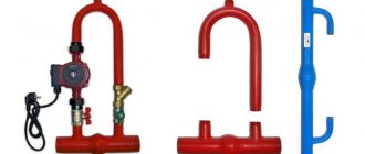
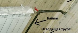
A bypass is a bypass part of the pipeline that ensures the coolant moves along a path that bypasses a certain section of the pipeline. One edge of the circuit is connected to the supply pipe, and the second to the return pipe. Various elements of the heating system, such as pumps, are usually installed on the bypass.
At the connection point between the bypass and the inlet pipe of the device that needs to be bypassed, a shut-off valve is installed. Its presence makes it possible to direct the flow of liquid parallel to the device itself and regulate the intensity of the coolant supply. A valve is also installed on the return pipe, which allows you to exclude a section of the pipeline from the system without the need to stop it.
Installation steps for a bypass valve (for radiators and with a circulation pump)
Installing a bypass valve with your own hands
Installing a bypass in a heating system equipped with a circular pump is done as follows:
- excess liquid is drained from the common pipe;
- a section of pipe measuring 40 cm is removed from the coolant;
- holes of the required diameter are cut at the ends of the pipe to connect the bypass;
- a filter is installed on the cut areas;
- then the bypass valve is installed;
- the hydraulic pump crashes.
Installation of a bypass in a heating system
For heating batteries, the following installation scheme applies:
- the diameters of the bypass and main pipes are checked;
- the following are mounted at the connecting ends: single-pipe jumpers and an adjustment valve;
- Next, the valve is installed at the closest possible distance from the heating radiator.
Necessary tool
You can install the bypass line yourself using installation tools, the list of which consists of the following items:
- tape measures for measuring the length and volume of a pipe;
- level for adjusting heating devices and water supply slope;
- pliers for removing and maintaining individual parts of the heating system;
- adjustable wrenches for joining the structure;
- a set of keys for installation (regular);
- metal cutter;
- screwdrivers: Phillips and flathead;
- pipe cutter (for large diameter pipes);
- welding machine;
- a grinding machine for leveling the corners of pipes and pipes;
- hammer drill;
- gas burner.
For a one-time job, it is not necessary to purchase all the tools, but you can rent them.
Recommendations and common mistakes
The insertion of the bypass valve should be done according to the rules of SNIP and the recommendations below:
- Before installation, it is advisable to install filters (mesh type).
- Installing monomers will help control water pressure.
- Do not twist, compress or stretch the pipes during installation.
- The average size of pipe joints should not exceed 5 DN before and 10 DN after the bypass.
The bypass valve can be mounted on horizontally and vertically directed sections of pipes, in accordance with the installation instructions.
Types of bypasses for heating
When installing a bypass, shut-off valves are installed not only on the pipes of the connected device, but also on the bypass itself. The type of fittings used allows us to classify several types of bypasses, each of which is suitable for certain operating conditions.
The following types of bypasses exist:
- Unregulated;
- With manual control;
- Automatic.
The characteristics of devices with different types of shut-off valves have significant differences, so before installing a bypass in the heating system, you need to carefully consider each type.
Saving
Undoubtedly, installing a bypass will have a positive effect on reducing your energy costs. For example, in comparison with the operation of a heating system with a closing section and a conventional flow-through one, the first of them will reduce the volume of coolant supplied to the batteries by approximately 30-35%. Thus, the heat transfer from the radiator can be reduced by 10%.
Of course, in practice, such changes are not such a dramatic improvement, especially if there is an excess of heat in the system. In addition, if the battery size is chosen correctly, then there is a margin of efficiency - also 10-15%.
Thus, it turns out that a fairly simple detail, even somewhat primitive, is a universal tool for creating a pleasant environment in your home, despite the fact that the bills will delight consumers with small amounts.
Unregulated bypass
The device of unregulated bypasses is a simple pipe that does not have any equipment. The pipe is constantly in an open state, and the liquid moves through it arbitrarily, that is, there is no opportunity to influence the intensity of the water flow. Unregulated bypass pipes are most often used to connect heating appliances.
When designing a heating system, it is necessary to take into account the fact that water always moves primarily through those areas where the hydraulic resistance is minimal. In the case of a bypass, this means that the internal diameter of its vertical section must be smaller than the internal cross-section of the main pipeline. If this requirement is not met, the coolant will simply gravitate towards the bypass.
When designing horizontal heating distribution, other rules apply that must be taken into account before making a bypass into the heating system. The heated coolant has a reduced specific gravity and always tries to move upward. In order for the system to operate normally taking into account this rule, the diameter of the lower part of the bypass must match the diameter of the main line, and the cross-section of the pipe leading to the radiator must be smaller.
Principle of operation
The principle of operation of the bypass valve
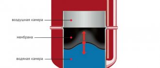
The principle of operation of the bypass valve in the gate structure is based on the counteraction of the pressure of the spring and water. The compressed spring presses on the valve on one side, and the working medium with great force on the other. The pressures of the combined components of the structure hold the bypass in the closed position. As soon as one of the potentials exceeds the permissible pressure (1.5 -2 times), it opens completely.
The degree of opening of the valve depends on the force of the working medium pressing on the valve. The damper creates the setting pressure using a spring. The level of compression affects the pressure drop of the system.
For reference! Bypass valves have low accuracy in maintaining pressure in heating devices.
Bypasses with manual adjustment
Bypasses that are adjusted manually (manual bypasses) are equipped with ball valves. The use of ball valves is determined by the fact that they do not change the pipeline capacity at all when switching, since the hydraulic resistance in the system does not change. This quality makes the ball valve an optimal option for bypass.
Shut-off valves of this type allow you to regulate the volume of liquid that passes through the bypass section. When the tap is closed, the coolant moves in full along the main line. The operation of ball valves has one important nuance - they need to be turned regularly, even if there is no need to adjust the system. This is due to the fact that if left stagnant for a long time, the taps may become tightly stuck and will have to be replaced. Sometimes a heating system feed valve is also installed, which plays a significant role.
Manual bypasses in heating systems can be used in several ways. Most often they are used to connect batteries to a single-pipe main, as well as for piping circulation pumps.
Scope and intended use
During a power outage, the need for a bypass for the circulation pump (its installation) ensures continuity of operation and eliminates emergency mode.
In pipeline structures, the shutter valve is designed for backup drainage of incoming liquid to a separate line (spare). If problems arise with water pressure in the pipes, the bypass valve closes access to the heating radiator, directing water in the opposite direction or to a separate channel.
Automatic bypasses
Bypasses with automatic adjustment are usually installed in the piping of a pump installed in a system with natural coolant circulation. Such heating systems can operate independently, but thanks to the pump, the speed of fluid movement along the circuit increases, which reduces heat losses and increases heating efficiency.
The presence of an automatic bypass in the pump piping allows the system to independently regulate its operation, i.e. no human intervention required. When the pump is running, the coolant passes through it, and the bypass is closed at this time. When the pump stops, the bypass opens and the liquid moves in it, while the stationary pump impeller cuts off the coolant flow.
Automatic bypasses are divided into two types:
- Valve;
- Injection.
The design of the first type of device contains a check ball valve. The hydraulic resistance of the valve is minimal, so the liquid easily moves on its own. When the pump is turned on, the coolant begins to move faster, is transported into the main line and diverges in two directions.
Further movement of the liquid occurs without any obstacles, and the reverse flow is blocked by the valve. The operating principle of the valve itself is extremely simple - the hydraulic pressure on the outlet side exceeds the inlet pressure, so the ball is pressed closely against the seat of the structure and does not allow the fluid to move.
Valve bypasses are quite convenient and simple, but they are very demanding on the quality of the water with which the heating system is filled. If the water contains various impurities, such as rust or scale, the valve very quickly becomes dirty and becomes unusable, as a result of which it has to be replaced.
Injection bypasses are devices similar in principle to a hydraulic elevator. A pumping unit is installed in the main line, which is connected to the main circuit using pipes of smaller diameter. With this scheme, both pipes are inserted into the main pipeline.
When the pump starts, part of the liquid enters the nozzle and is passed through the apparatus, accelerating many times in the process. The outlet pipe, which is slightly narrowed and visually resembles a nozzle, which ensures efficient pumping of liquid, also works to increase speed.
A vacuum is created behind the outlet pipe, due to which the coolant begins to be sucked out of the bypass. The flow, moving under pressure, pulls all the liquid with it, and it continues to move along the main highway with noticeable acceleration. This effect allows you to completely prevent the possibility of reverse flow of liquid.
The technology described above only works when the pump is turned on. If the pumping equipment is turned off, then the coolant in full passes through the bypass under the influence of gravitational forces.
Where is it?
Location of the bypass valve in the engine compartment (circled in red)
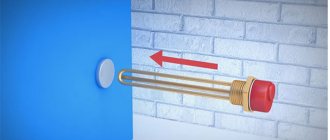
You need to look for a bypass near the turbine. The bypass valve is installed in that part of the intake manifold that is located after the turbine and before the throttle valve. When excess pressure arises in the intake tract, the bypass simply bleeds it off, sending it back to the intake manifold, to the area in front of the turbine. Thus, the air pressure in the intake manifold is reduced to an acceptable level.
When removed, the part has an L-shape - two air duct fittings are located perpendicularly on the cylindrical body. Additionally, at the top of the valve there is a thin outlet to create air vacuum. When the part is installed on the car, only the central cylindrical part of the body is visible, because the fittings are hidden in the air duct pipes.
Bypass purpose
The main function of any bypass is the ability to keep the heating system in working order even if one of its elements breaks down or there is a power outage. Devices connected via bypass can be disconnected from the system without any problems - to do this, you just need to turn off both taps, and the coolant will flow around the circuit.
Thanks to the bypass, heating can continue to operate in any case, and damaged elements can be repaired, spending any amount of time. The reliability and ease of maintenance of the heating system with a bypass increases many times over.
In autonomous heating circuits, the bypass is used to solve the following problems:
- Connecting heating devices to single-pipe wiring;
- Pumping equipment piping;
- Connecting the water heated floor distribution manifold;
- Formation of a small circulation circuit when using solid fuel heating equipment.
The bypass installation method may vary depending on its purpose in a particular heating system.
Battery tying
If the installation of the system is carried out independently, then you need to know all the requirements that apply to this or that element. This also applies to the bypass. It is often installed in places where radiators are mounted. But why do you need a bypass in a heating system? This issue needs to be looked at more carefully.
Radiators are tied according to a simple pattern
Why is it needed?
Previously, single-pipe heating was used in the construction and improvement of houses. This greatly simplified the work and also reduced costs. In this case, two collectors were installed in the elevator unit, which were responsible for supplying and processing the coolant. Further heating was developed according to different schemes:
- Top feed. There was a pipe running from the collector to the top floor. The coolant was supplied upward through this riser. After that, it went down, passing through all the radiators.
- Bottom feed. In this case, the coolant begins to flow into the radiator when it is raised up. This series connection of devices has some disadvantages.
In both the first and second cases, the connection is made in series. This means that if a problem occurs on some equipment, you will have to turn off the entire system. To circumvent this problem, special jumper pipes were included in the system. So, if necessary, the radiator is disconnected from the system using taps without disturbing its operation. This makes it possible to easily repair the battery.
The jumper is installed closer to the battery
This is not the only reason for using a jumper in heating. The room is heated using radiators. If there is a bypass with valves, apartment owners have the opportunity to independently adjust the coolant supply. Thus, controlling the temperature in the house is not difficult.
The dressing tube has different shapes
Bypass installation
To carry out heating installation, you must have certain knowledge and skills. This takes into account the method of pipeline assembly. For this purpose, threaded and fitting connections are used, as well as pipe soldering. Having these skills will make the job easier. It is worth considering some rules and recommendations from experts:
- There should be no valves between the rack and the bypass. Otherwise, the coolant circulation may be disrupted.
- On the vertical riser pipe, the jumper is mounted in close proximity to the battery. In this case, space must be provided for installing shut-off valves. It is mounted on both sides of the radiator.
- Do not install valves on the bypass unless necessary. If you install taps on the jumper, the circuit will become unbalanced. In an autonomous system of a private house, this in turn allows you to redirect the flow. In a multi-story building, this option is ineffective and is a violation of standards.
- The size of the pipes is important. The diameter of the insert is two sizes smaller than the section of the stand. The pipes that go to the radiators are made one size smaller. In the horizontal scheme, the size ratio is somewhat different.
Compliance with the dimensions of pipes and pipes will ensure normal operation of the system, in accordance with all the laws of hydraulics. As for installation, its features directly depend on the type of material used. If we are talking about a metal pipeline, then it is enough to simply weld the jumper and install the taps.
Installation is carried out in different ways
The use of polypropylene, as well as metal-plastic, requires the use of special fittings. You can build a bypass yourself from a pipe of the required size or purchase a ready-made part.
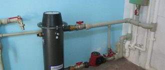
The pump is often installed on a jumper
Bypass for radiator
In single-pipe heating systems, batteries are best connected using a bypass. For two-pipe circuits and manifold distributions, bypasses are not needed, since all heating devices are connected in parallel, and each of them receives coolant at the same temperature. If one of the batteries fails, it can always be removed without turning off the heating system (of course, if there are shut-off valves).
In systems with single-pipe wiring, the batteries are connected in series, so the coolant in each subsequent device cools down. The result is obvious - distant devices receive much less heat, and there can be no talk of any uniform distribution of thermal energy.
Bypasses can solve the problem. The supply and return circuits are connected by a jumper, which ensures independent flow movement. The hot coolant enters directly into the radiator, while the other part of it passes further and at the outlet is mixed with cooled water from one radiator. This scheme allows you to deliver much more heat to subsequent heating devices.
The effect of bypass on heat transfer
The use of the element in heating networks allows one to obtain excellent results in terms of thermal energy savings. In this case, the production of a bypass can be carried out directly by a foreman at the work site, or it can be a factory model with standard characteristics.
It is a piece of pipe that is installed into the network using tees. Install it approximately one-third of the distance from the riser to the radiator. It cannot be placed further because the coolant will not flow into the radiator; placing it too close may cause the bypass to overheat and the circulation will be disrupted again. Therefore, one third is the most optimal ratio.
After this engineering element, needle valves are placed in front of the radiator, thus making it possible to fine-tune the thermal output of radiators for each individual element, without consequences for steel heating devices. An unobvious advantage of the installation is the ability, if necessary, to carry out scheduled and unscheduled repairs and maintenance of a radiator that suddenly fails, without shutting down the entire system.
The location of the product can be either vertical or horizontal. It can be used in both single-pipe and two-pipe heating systems
It is important to remember that the diameter of the pipe in the bypass must always be smaller than the diameter of the pipes through which coolant is supplied to the radiator; this will, due to natural resistance, prevent disruption of coolant circulation
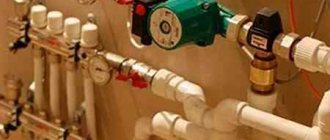
Connecting the pump via bypass
It is advisable to connect the circulation pump via bypass only in those systems that were originally designed for natural circulation, i.e. they must have an accelerating manifold, pipe slopes must be observed and their diameters must be correctly selected. The pump in such systems is not intended to ensure their operation, but to increase efficiency.
For systems that were designed for forced circulation at the design stage, a bypass is simply irrelevant. Such systems operate only due to the pump, so when it is turned off, the circulation of the coolant simply stops. Bypass in this case will not solve the problem.
When connecting the pump via a bypass line, it becomes possible for counterflow in the bypass. In addition, a closed circulation loop is formed between the pump and the bypass itself. In order for such a circuit to function normally, the bypass device must be equipped with a ball valve or check valve.
When the pump is running, the device blocks the flow of liquid through the bypass pipe. The valve does this work automatically, but the tap has to be adjusted manually. When the pump stops, the bypass opens, which allows coolants from different circuits to mix. A similar scheme is not applicable in the case of injection bypasses - they completely eliminate the possibility of reverse coolant flow.
How to choose a valve for a boiler and bypass
In the factory configuration, boilers and bypasses are either equipped with the simplest bypass valve or do not have a device for redirecting the flow.
In the first case, you can not interfere with the design of the water heater or bypass element and install them in their existing form.
In the second case, it is necessary to purchase and install bypass valves. A bypass without this device will only allow the flow of the working medium to pass when the heating circuit is turned off, but will not be able to regulate the pressure. A boiler that is not equipped with a bypass valve is susceptible to overheating and may break down, since the water in it will boil and turn into steam, further increasing the pressure on the pipes and the heating unit itself.
The choice of device depends on the heating or water heating device: the fuel it uses, the maximum permissible pressure specified in the technical documentation.
The price of the product in this matter can only play a role when choosing between similar devices from different manufacturers.
We recommend that you read: Which heating is better and how to install it in a private house
Different types of heating devices require valves of different designs:
Systems running on electricity, gas or diesel fuel are undemanding - to regulate the pressure in them, a simple bypass valve that does not have additional elements is sufficient. Solid fuel does not stop burning immediately, therefore it is impossible to immediately turn off the solid fuel boiler or smoothly adjust the heating temperature
Therefore, in solid fuel heating systems it is important not only to regulate the pressure, but also to cool the heat-generating unit. Bypass valves are installed on bypasses and boilers, which respond to both an increase in pressure and an increase in the temperature of the coolant. Such devices are equipped with a temperature sensor, a coolant discharge and replenishment system and are connected to a sewerage system and a cold water supply system.
A bypass valve with a control handle should only be installed if the homeowner already knows how to set the pressure limit. If you try to acquire this skill in practice, you can break the device, cause an accident, or get burned. For open-type thermal circuits, bypass valves are not required - the compensation tank copes with the task of regulating pressure without them. The technical characteristics of the bypass valve must correspond to the parameters of the heat source: the control valves must be set to the same maximum pressure as the heat-generating device and have a flow capacity no lower. It is also important that the dimensions of the connecting pipes match - if this condition is not met, you will have to use fittings for the connection, which will make the system more vulnerable
Such devices are equipped with a temperature sensor, a coolant discharge and replenishment system and are connected to a sewerage system and a cold water supply system. A bypass valve with a control handle should only be installed if the homeowner already knows how to set the pressure limit. If you try to acquire this skill in practice, you can break the device, cause an accident, or get burned. For open-type thermal circuits, bypass valves are not required - the compensation tank copes with the task of regulating pressure without them. The technical characteristics of the bypass valve must correspond to the parameters of the heat source: the control valves must be set to the same maximum pressure as the heat-generating device and have a throughput not lower
It is also important that the dimensions of the connecting pipes match - if this condition is not met, you will have to use fittings for connection, which will make the system more vulnerable
Specifications
Each bypass valve is characterized by several parameters, which should also be taken into account when choosing a product:
| Characteristic name | What does it mean |
| throughput | volume of coolant consumed per unit time at unit pressure |
| nominal pressure | maximum excess pressure of the working environment, maintained at 200 degrees |
| nominal diameter | the internal cross-section of the connecting pipes may have a slight deviation from the actual size |
| setting range | limits of the maximum pressure adjustable on the valve |
For heated floors
When installing a heated floor, it is imperative to install a mixing unit, in which a bypass pipeline is always built in. The bypass in this case will be used to ensure the normal operation of the heated floor, and without this element the heating will not be able to function.
It's all about the operating temperature, which must be maintained in heated floors. The coolant in the supply circuit can heat up to 80 degrees, but in a heated floor its temperature should not exceed 45 degrees. The liquid is brought to the required temperature in a mixing unit, which passes only the required volume of hot water. The entire remaining flow is directed to the bypass, where it is connected to the coolant from the return circuit, and returns to the boiler.
Advantages of using a valve in a heating system
The bypass valve insert has the following advantages:
- reduces rust levels;
- regulates heating temperature;
- prevents noise of unnatural origin;
- reduces the load on the hydraulic pump.
The following errors when installing a bypass valve can lead to a complete replacement of pipes in the room:
- installation of a pump with a wet rotor;
- incorrect valve location;
For reference! If leaks near the manual tap are not eliminated, the pipe may bend.
Energy Saving
Installing a simple engineering solution, such as a bypass valve, will save energy costs, since the heat transfer of the heating radiator increases by 10%. In this case, the volume of coolant, with the bypass valve included in the package, will increase to 30%.
Source
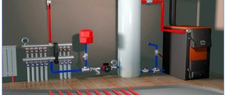
For systems with solid fuel boiler
When used in combination with solid fuel heating equipment, the bypass allows the formation of a small circulation circuit. To do this, the bypass pipe is installed in the supply, where there is a coolant heated to the limit, and is connected to a three-way valve located on the opposite side of the structure.
Thanks to the valve, hot water from the bypass and cold water coming from the return circuit are mixed. As a result, a coolant whose temperature exceeds 50 degrees is returned to the boiler for the subsequent heating cycle.
The need to return warm liquid to the boiler is determined by the fact that otherwise condensation will appear on the metal walls of the combustion chamber, which will provoke corrosion and cause damage to the unit. If you supplement the system with a bypass, then these problems can be easily avoided.
Types and designs
According to the operating principles, bypass valves are distinguished with spring and membrane designs. Spring mechanisms prevail in systems where the pipeline cross-section is no more than 200 mm; in other water supply and heating networks, the lever-load principle is used.
Membrane units are increasingly used when working with liquid media that contain solid particles.
Depending on the pipeline environment, bypass devices are intended for:
- gas;
- pair;
- liquids.
According to the purpose of the system, they are used for pipelines:
- cold water supply,
- hot water supply,
- heating,
- cooling,
- conditioning.
In heating and water supply systems, bypass valves are distinguished according to their purpose:
- for radiators;
- for boiler and bypass;
- for automatic replenishment;
- for low or high pressures.
This photo shows an overflow valve with a setting scale. Made of bronze and brass, designed for installation in central heating systems.
Along with bypass regulators, the following is installed in the heating design:
- air vent to prevent air locks in pipes;
- three-way valve for mixing or separating hot and cold water flows;
- reverse, preventing backflow in the pipeline.
For industrial and utility networks, designs with a nominal diameter DN of up to 500 mm and a flange connection are used.
In the car there are access devices for:
- turbines;
- fuel supply mechanism;
- engine cooling systems.
The turbine bypass unit discharges the exhaust gases, reducing the pressure force in the manifold. Thus, it protects the engine from overheating.
Bypass installation
Including a bypass in different types of systems has its own nuances, so before making a bypass for heating, you need to understand these points.
For example, when connecting radiators via bypass, the following rules must be observed:
- The internal cross-section of the bypass should be one step smaller than the diameter of the main pipe;
- The bypass must be installed at a minimum distance from the radiator;
- When used in apartment buildings, the bypass cannot be equipped with a tap.
Installation of a heating system bypass can be carried out both when installing a new system, and when repairing an existing structure. In the latter case, before work you need to prepare a set of pipes of suitable diameter, two tees and shut-off valves.
The inlet pipe of the structure is equipped with one of the following devices:
- Ball valve, which has minimal hydraulic resistance and completely allows coolant flow;
- A valve that allows you to manually adjust the intensity of liquid flow;
- A combination of a ball valve and an automatic thermostat - this combination can adjust the operation of the system automatically.
The outlet pipe is always equipped with a ball or shut-off valve. To connect individual elements, welding or threading can be used. Regardless of the type of connection, it must be airtight. Before putting the system into operation, you need to check it for leaks.
A bypass with a pump in the heating system is installed taking into account the following points:
- The bypass on which the pump is planned to be installed is usually part of the main line. The internal diameter of the bypass must be large enough to ensure normal natural circulation in the system. The pump is mounted on a separate pipe, the internal cross-section of which may be smaller than the diameter of the main pipeline.
- To simplify your work, it is best to buy a pre-assembled pump unit with the necessary parameters. It is very simple to install such a structure, since all the elements are already correctly assembled and the connections are quite reliable.
- When installing it yourself, the pump must be positioned so that the impeller axis is horizontal. The surface with the terminals to which power is supplied should be directed upward - firstly, this will simplify access to the contacts, and secondly, it will eliminate the possibility of liquid getting on the contacts if the system’s seal is broken.
- The area with a bypass must be equipped with a check valve or ball valve, which prevents the flow of coolant in the opposite direction - this optimizes the operation of the system. Of course, before installing the bypass, you need to purchase all the components.
Before installing a bypass with a check valve for the circulation pump, you need to think carefully about the design of the future system and take into account all possible nuances.
Installation errors
Some home, or rather, apartment craftsmen, when replacing old cast-iron radiators with new aluminum ones, deliberately make two stupid mistakes:
- install a ball valve on a straight bypass pipe in order to direct all the coolant into its own battery;
- Having listened to the advice of “smart” people, they assemble a mixing unit with a three-way valve in order to regulate the heat transfer of the heating device.
Let’s immediately make a reservation that such installation in a private house is not considered a mistake: you live there alone and control the heating yourself. In a high-rise building, such actions harm your neighbors, since you unbalance the system and take away more heat. This means that adjacent apartments receive less. How this happens, watch the video:
Instead of further listing the errors, we suggest that you familiarize yourself with the recommendations on how to properly install the bypass yourself:
- The jumper on the battery of an apartment building is a pipe without any shut-off fittings or valves. The maximum that is allowed is to reduce the diameter by 1 standard size (riser DN 20 - connector DN 15);
- If you want to regulate the heat transfer of radiators, please install manual or automatic thermostats. There are special full-bore models for centralized networks.
In multi-storey buildings with common risers, it is unacceptable to install fittings on the bypass pipeline - If energy-independent gravitational heating is installed in a country house, install the pump only on the bypass. Gravity flow is not provided - no jumper is needed.
- When assembling mixing units yourself, make sure that the circulation pump is on the side of the open outlet of the valve. Other options don't work.
- A three-way valve equipped with a thermal head operates from a remote temperature sensor. Place the latter on the pipe behind the valve, where the mixed coolant exits. Then the element can be guided by its temperature.
Point #3 requires clarification. With 3-way valves, one pipe is always open - the one from which the resulting mixture comes out. A pump is installed on the same side. If the unit is placed on any inlet pipe, then further events will follow one of two scenarios: the circulation will stop or the coolant will flow through the bypass, close in the boiler circuit and not get into the radiators.
Differences from other types of safety valves
Other valves installed for the safe operation of pipelines have a similar device and principle of operation. But they differ in purpose and requirements.
| Valve type | Mechanism of action | Principle of operation |
| Bypass | Installed in a bypass circuit and redirects part of the flow into it | Constantly working as needed |
| Safety | Reduces pressure in the system, throwing part of the media out | In case of emergency pressure increase |
| Reducing | By changing its throughput, it regulates the pressure in the part of the main circuit located after its installation site | Full time job |
The bypass valve reduces the load on the system pumps without changing the amount of media in it.
Tips and tricks
If you are going to install a bypass in your central heating, you must notify housing and communal services representatives about this (in writing). They must coordinate the temporary shutdown of heating with the boiler room. Each installation of gas equipment in an apartment or private house is accompanied by an order from the project owner from a public or private designer. We advise you to check all the components indicated in the papers, so that after you accept the project there are no misunderstandings due to the absence of something on the diagram, but the presence of this part in the finished product. In case of installation of an electric boiler with a power of up to 5 kW, a project order is not required
But the installation of the system must be carried out with an invited specialist in order to avoid critical errors. When buying a boiler, pay attention to the quality and safety certificates. This will save you and those around you from unexpected breakdowns and accidents. When the pipeline is assembled using soldered PVC pipes, you need to monitor the pressing force at the moment of soldering the joints. Excessive pressure on the heated ends of the joint will lead to clogging of the flow force of the heat exchanger.
Excessive pressure on the heated ends of the solder will lead to clogging of the flow force of the heat exchanger.
Fuel pump hp-Technik UHE series with bypass valve and bypass
Fuel pump hp-Technik UHE series - with bypass valve and bypass.
Fuel pumps are used in oil burners and pumping stations to create the pressure necessary for equipment operation and pump fuel.
Areas of application for hp-Technik fuel pumps:
Combustion systems
Boiler burners, closed circulation pipelines, pumping all types of liquid boiler and marine fuels EL, L, M, S, ES, coal tar and coal oil, tar, kerosene, etc.
Mechanical engineering
Hydraulic pumps for control units of hydraulic systems, lubrication pumps for pumping lubricating oils and greases, pumps for water cooling systems for supplying oil-water emulsion.
Oil industry Feed (pressure) pumps for oils, mineral lubricants, tar, resins, tar, bitumen, etc.
Shipbuilding Lube oil pumps and booster pumps for supplying marine lubricants, diesel fuel, fuel oil and heavy viscous oils.
Advantages of hp-Technik fuel pumps:
Self-priming, self-lubricating, vibration-free, silent, maintenance-free, with hermetically sealed shaft.
Instructions for the fuel pump hp-Technik UHE series
| Direction of shaft rotation: I – Reverse direction (counterclockwise). | ||||||||||||||
| UHE series pump models | Working fluid viscosity, cSt: 6.0 at 20 °C | Gear rotor, F | Val,F | Threaded connection for (S/A/R) | Pressure meter connection (M1/M2) | Max. shaft rotation speed, rpm | Weight, kg | |||||||
| Flow, l/h at 1400 rpm | Flow, l/h at 2800 rpm | |||||||||||||
| Art. No. I | 9 bar | 30 bar | 40 bar | Art. No. I | 9 bar | 30 bar | 40 bar | |||||||
| UHE-A2-PZ | 05110542 | 200 | 155 | 140 | 05130542 | 500 | 380 | 330 | 38 | 12 | G 1/2″ | G 1/4″ | 3500 | 4,4 |
| UHE-A3-P | 05110543 | 300 | 260 | 240 | 05130543 | 700 | 600 | 550 | 38 | 12 | G 1/2″ | G 1/4″ | 3500 | 4,6 |
| UHE-A4-M | 05110544 | 450 | 425 | 390 | 05130544 | 900 | 850 | 800 | 38 | 12 | G 1/2″ | G 1/4″ | 3500 | 4,8 |
| UHE-A5-GZ | 05110545 | 550 | 500 | 450 | 05130545 | 1300 | 1150 | 1050 | 38 | 12 | G 1/2″ | G 1/4″ | 3500 | 5,0 |
| Shaft rotation direction: D – Direct direction (clockwise). | ||||||||||||||
| UHE series pump models | Working fluid viscosity, cSt: 6.0 at 20 °C | Gear rotor, F | Val,F | Threaded connection for (S/A/R) | Pressure meter connection (M1/M2) | Thermal power H1, W at 220 V, 50 Hz | Torque, M (Nm) | |||||||
| Flow, l/h at 1400 rpm | Flow, l/h at 2800 rpm | |||||||||||||
| Art. No. D | 9 bar | 30 bar | 40 bar | Art. No. D | 9 bar | 30 bar | 40 bar | |||||||
| UHE-A2-PZ | 05120542 | 200 | 155 | 140 | 05140542 | 500 | 380 | 330 | 38 | 12 | G 1/2″ | G 1/4″ | 110 | 1,6 |
| UHE-A3-P | 05120543 | 300 | 260 | 240 | 05140543 | 700 | 600 | 550 | 38 | 12 | G 1/2″ | G 1/4″ | 110 | 1,6 |
| UHE-A4-M | 05120544 | 450 | 425 | 390 | 05140544 | 900 | 850 | 800 | 38 | 12 | G 1/2″ | G 1/4″ | 110 | 1,6 |
| UHE-A5-GZ | 05120545 | 550 | 500 | 450 | 05140545 | 1300 | 1150 | 1050 | 38 | 12 | G 1/2″ | G 1/4″ | 110 | 1,6 |