Brief overview of modern models
To get an impression of the brands and models of water heaters, let’s look at several devices from different manufacturers.
Heaters KSK-3, produced at the company T.S.T.
Specifications:
- coolant temperature at the inlet (outlet) - +150°C (+70°C);
- inlet air temperature – from -20°С;
- working pressure – 1.2 MPa;
- maximum temperature - +190°C;
- service life – 11 years;
- working resource – 13,200 hours.
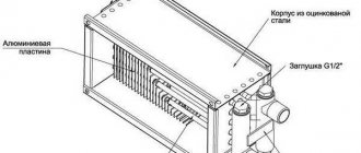
External parts are made of carbon steel, heating elements are made of aluminum.
The Volcano mini water fan heater is a compact device from the Polish brand Volcano, characterized by practicality and ergonomic design. The air flow direction is adjusted using controlled blinds.
Specifications:
- power within 3-20 kW;
- maximum productivity 2000 m?/h;
- heat exchanger type – double row;
- protection class – IP 44;
- maximum coolant temperature 120°C;
- maximum working pressure 1.6 MPa;
- internal volume of the heat exchanger is 1.12 l;
- guide blinds.
Galletti AREO heater made in Italy. The models are equipped with a fan, a copper-aluminum heat exchanger and a drainage tray.
Specifications:
- power in heating mode – from 8 kW to 130 kW;
- power in cooling mode – from 3 kW to 40 kW;
- water temperature – + 7°C +95°C;
- air temperature – 10°C + 40°C;
- working pressure – 10 bar;
- number of fan speeds – 2/3;
- electrical safety class IP 55;
- motor protection.
In addition to the devices of the listed brands, on the market of heaters and water air heaters you can find models of the following brands: Teplomash, 2VV, Fraccaro, Yahtec, Tecnoclima, Kroll, Pakole, Innovent, Remko, Zilon.
First operating experience
Operation and first measurements:
- from September 30, the supply water temperature was raised to 40 °C.
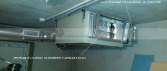
- at this temperature, the system operates normally at a speed of 40% (about 150-200 m3/hour), the maximum temperature in the channel is up to 28 ° C (pictured above). And this is with the recirculation pump turned off.
- If you turn on the pump, the three-way valve is in an almost closed position. This is encouraging that there is power reserve.
I took measurements on the meters of all apartments on the site for 2 days with the pump turned off
- 2-room 85 m2 - 78 kW*hour
- 1-room 50 m2 - 44 kW*hour
- 1-room 45 m2 - 43 kW*hour
- 3-room 110 m2 – 76 kW*hour
The next 2 days with the recirculation pump turned on
- 2-room 85 m2 - 77 kW*hour
- 1-room 50 m2 - 44 kW*hour
- 1-room 45 m2 - 41 kW*hour
- 3-room 110 m2 - 77 kW*hour
We can draw preliminary conclusions that:
- the inflow does not affect the consumption of neighbors, at least under the current parameters.
- I’m glad that it wasn’t in vain that I spent a lot of effort on insulating the external walls - I spend about two kopecks on heating
The first month of operation has ended.
- There was an unpleasant moment - the electricity was turned off in the whole house. At the same time, the heating pumps in the basement also stopped.
- the air inlet tried to restart automatically somewhat, but my recirculation pump was turned off and every time it crashed due to a freezing accident in the heater.
- I turned off the automatic restart and bought an uninterruptible power supply to power the pump.
First month of operation - October 2013:
- Water meter readings - 983 kWh, including batteries
- electricity for supply - 42 kW*hour (the water temperature was low for two days, the electric heater was turned on)
- last year the inlet was heated by electricity - it spent 340 kW*hour.
- 2-room 85 m2 - 1102 kW*hour
Second month of operation - November 2013:
- Water meter readings - 1170 kWh, including batteries
- electricity for supply - 39 kW*hour
- 2-room 85 m2 - 1132 kWh. Average - 13.3 kWh/m2
In the first three months of operation, I saved 3,000 kW on electricity—about 10,000 rubles.
Types of air heaters
The efficiency and heating rate of air from a steam heater is higher than that of electric and water heaters
Duct heaters are classified according to the type of coolant. The following types are distinguished:
- Electrical. A metal heating element is used as a heating element, which operates from the mains. The device is easy to install and install. The power is designed to serve a room up to 100 sq.m.
- Mermen. These are devices in which water circulates through pipes. Used in ventilation systems in public and industrial premises. It is necessary to install the water heater piping unit.
- Steam. A heater powered by steam has a high efficiency and a high heating rate. The steam is heated to a certain design temperature. Suitable for installation in industrial buildings with a source of water vapor. The piping of a steam air heater for supply ventilation is complex, so it should only be done by specialists.
The choice of the optimal system depends on the type of room, its purpose and capabilities.
Classification
To create an optimal microclimate in the building, a calorific heating system is used, that is, forced heating using equipment that is installed in air ducts.
Depending on what coolant is used, there are 4 types of heaters:
- Steam - used most often in industrial enterprises where steam production is provided for by technological processes.
- Electric - this option is the easiest to install (you only need a power source to heat the built-in heating elements), but it requires a lot of electricity consumption. The use of an electric heater is considered appropriate only in facilities whose area does not exceed 150 m²
- Water - this type of heater operates on the basis of hot water and is installed in ventilation systems with a rectangular or round cross-section in areas over 150 m². This type of heating is reliable, practical, easy to maintain and inexpensive.
A special feature of the heater is that the composition of the air flow coming from the street should not be sticky, fibrous, or contain solid particles. Permissible dust content is no more than 0.5 mg/m³. Minimum intake air temperature -20 °C.
When choosing a heater, the following factors are taken into account:
- room area;
- weather conditions in a given climate zone;
- ventilation power.
The heater is installed in the inside of the ventilation shaft, so it must correspond to its parameters (configuration and size).
If the performance is low, the device will not be able to warm up the air masses.
If it is not possible to install a heater with the required parameters, then several mechanisms with lower power are mounted in series.
Schemes and types of designs of UTK mixing units
The mixing unit is built according to a three-way control scheme
Ball valves 1 serve to disconnect the unit from the heating network.
There is a filter 2 for hot water on the supply line of the unit. When dirty, the filter element must be cleaned.
A three-way control valve with a servo drive 3 of proportional control is installed on the supply line of the unit. Input B of the valve is connected by a bypass to the return line of the unit. A check valve 5 is installed on the bypass to prevent coolant from flowing from the supply line to the return line, bypassing the air heater. A circulation pump 4 is installed on the supply line of the unit to ensure circulation of the coolant through the “small” circuit.
Automatic control
The electrical circuit was designed using SPlan7.0. Scheme in
.
To protect against leaks, I additionally installed NEPTUN BUGATTI BASE 1/2 INCH. I brought the emergency contacts to the Controller, and additionally turned off the circulation pump.
The installation of the shield was carried out mainly using ABB components, only taking power relays from Legrand. The power part is assembled at the bottom of the panel, the low-voltage and signal parts are at the top.
Automated air heating in supply ventilation
Options for constructing round and rectangular ventilation shafts - the system is automated
- The operation of the equipment is controlled using a control panel (CP). The user presets the mode for regulating the supply air flow and temperature.
- Using a timer, the heated ventilation system automatically turns on and off.
- Equipment that provides heating can be connected to an exhaust fan.
- Heaters are equipped with a thermostat that prevents fire.
- A pressure gauge is installed in the ventilation system to monitor pressure differences.
- A shut-off valve is installed on the supply ventilation pipe; it is designed to block the entry of incoming wind masses.
(no votes yet)
System installation
On the balcony side, the circuit changed, the input muffler was removed, and another G5 filter was installed in front of the fan instead. There is a valve on the main ventilation channel, bypassing the heaters; in winter mode it is closed - the air will flow through the heaters.
With the help of a janitor, a hole was made in the wall onto the balcony. It's good that walls are easy to break down. The inside is foam concrete, then 15 cm of polystyrene foam and facing the floor with bricks. The layout of the apartment made it possible to create a small storage room measuring 50x50 cm in the corner near the balcony.
The task was complicated by the fact that it was necessary to place the muffler (length 110 cm, diameter 30 cm) after the heater. Because of this, the installation turned out to be very tight.
Using a drill, some kind of thing and a round bend, I cut into the main ventilation duct, which runs under my ceiling. To the left of the new insert you can see the air conditioner's air intake for recirculation. Installed a silencer. It weighs about 5 kg, so it rests on supports.
I tried on the air heaters. Everything fits in smoothly, the margin is only a couple of centimeters. The distance between electric and water turned out to be too small - at least two diameters are needed. This was one of my serious mistakes.
Installation and connection features
Assembly and connection work must be carried out by professional workers from a specialized company. Before starting equipment installation work, it is necessary to check the condition of all elements and components of the mixing unit, the integrity of the insulation of the electrical wires of the drive and circulation pump.
Requirements for installation of electrical equipment
- The pump must be connected to the electrical network using a three-wire cable.
- It is necessary to install a junction box on the pump casing, where the phase, neutral and ground connections are connected. The terminals must be accessed by unscrewing the screw element in the middle of the protective cover of the box.
- The electrical cable must be removed from the junction box through an insulating ring.
- It is prohibited to supply current to the electrical cable until installation work is completed.
- Maintenance work must only be carried out with the mixing unit switched off.
To prevent emergency situations during the operation of mixing hydraulic units of ventilation systems, it is necessary to accurately calculate and select the standard sizes of valves, additional elements, pump power, etc. that meet the requirements.
Adjusting the heating process
There are 2 types of heating adjustment:
- quantitative – temperature adjustment occurs due to changes in heat resource consumption;
- high-quality - this option uses a change in the parameters of the heat carrier while maintaining constant consumption of heat resources.
Installation of the mixing block. Installation methods
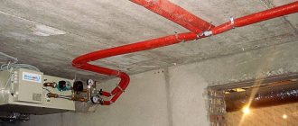
The piping module is constructed using rigid wiring, i.e., all elements are connected using steel or plastic pipes. In this case, the location of the module is known in advance. All parts of this block are located in close proximity to each other. This simplifies the installation, maintenance or repair of the mixing unit.
Two schemes for piping the thermostatic module have found practical application:
- High quality;
- Quantitative.
The first option, which ensures temperature control by the coolant while keeping its volume constant, is used today much more often than the other. The second scheme is based on a method of thermal regulation by changing the amount of coolant. Here, the volume of thermal energy and the heating temperature of the air are directly proportional.
Depending on the type of circuit provided, it includes either a two-way valve and a pump (quantitative method), or a three-way valve - with a qualitative heating method. In addition to these components, a typical steam heater piping unit includes:
- Ball valve for supply and removal of coolant;
- Coarse mesh filter;
- Bypass, which prevents the coolant from stopping as a result of sudden blocking of the solenoid valve;
- Thermometers, pressure gauges, piping.
In addition to rigid wiring, the method of threaded connection of circuit elements using corrugated hoses is also used. This option is used when rigid assembly is not possible.
Heater thermal power reserve
9. Determine the thermal performance reserve of the adopted heater(s). ((q - Q) / Q) • 100 q - actual thermal power of the selected air heaters, W; Q is the calculated thermal power for heating the required volume of air, W. The actual thermal performance of the adopted steam-air heater must be greater than the calculated one. The range of the permissible percentage ratio of actual and calculated power, according to various sources, can be from 96 to 120 (from - 4 to 20)%. In any case, you need to strive for the closest possible equality of power (actual performance = 100 - 110% of the calculated one). If, during the calculation, the difference is greater than the above figures, a recalculation should be made.
An example of calculation and selection of a KPSk heater. Step-9
Select a suitable KPSk heater for heating 6500 m³/hour from a temperature of -28°C to +29°C. The coolant is dry saturated steam with a pressure of 0.1 MPa. 9. We calculate the discrepancy between the actual and calculated thermal power of the selected heat exchangers ((104653 - 133426) / 133426) • 100 = -21.6% - for the KPSk 2-10 air heater ((150642 - 133426) / 133426) • 100 = 12.9% - for heater KPSk 3-10 ((188874 - 133426) / 133426) • 100 = 41.6% - for heater KPSk 4-10 104653, 150642, 188874 - actual thermal power of the selected steam heat exchangers, W; 133426 — calculated thermal power for heating a given volume of air, W. -21.6, 12.9, 41.6 — thermal performance reserve of the selected air heaters. Of the considered models of heaters KPSk number 10, only the three-row air heater KPSk 3-10 corresponds under given conditions to the recommended ratio of actual and calculated power.
CONTROL VALVES
Control valves ESBE (Sweden) VRG 131 series:
Valve material: DZR brass.
Maximum operating temperature +110°С (short-term up to +130°С)
Maximum operating pressure 10 Bar.
Transmittance 0.02%.
| Valve model | Valve Kvs | Attach. size |
| VRG 131 15-1.6 | 1,6 | G 1/2″ |
| VRG 131 15-2.5 | 2,5 | G 1/2″ |
| VRG 131 20-4.0 | 4 | G 3/4″ |
| VRG 131 25-6.3 | 6,3 | G 1″ |
| VRG 131 25-10 | 10 | G 1″ |
| VRG 131 32-16 | 16 | G 1 1/4″ |
| VRG 131 40-25 | 25 | G 1 1/2″ |
| VRG 131 50-40 | 40 | G 2″ |
| 3F50 | 60 | F 2″ |
| 3F65 | 90 | F 2 1/2″ |
| 3F80 | 150 | F 3" |
Strapping methods
The piping is a frame made of reinforcement, with the help of which the flow of hot water is regulated. The piping unit helps to monitor the performance of the supply ventilation heater, control it and maintain a given temperature regime in the building. The location of the piping units is determined by the installation location, air exchange diagram, and technical parameters of the equipment. There are 2 installation options:
- Recirculated air masses are mixed with supply air.
- Only indoor air is recirculated according to a closed principle.
Taking this into account, there are 2 methods of strapping:
- 2-way valves - with uncontrolled reverse water flow;
- 3-way valves - when controlling water flow in a boiler room or boiler room.
Some produce piping units of various modifications, which are entire sets consisting of valves (balancing and check valves, two and three-way), pumps, bypasses, ball valves, pressure gauges, and cleaning filters.
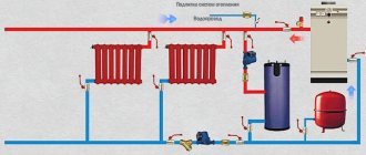
Scheme of piping heater units for supply ventilation. (Ball valves installed at the inlet and outlet allow you to shut off the water, and a thermomanometer allows you to control temperature and pressure)
If natural ventilation is well established, then there are much more opportunities for successful operation of the equipment. The correct choice of piping in such cases is effective both for heating large areas in production and for private houses and cottages.
The heater used for ventilation is usually connected to the heating system directly at the air intake point. If forced ventilation is in effect, then the air heater can be installed anywhere. Air heaters for forced ventilation allow you to create a comfortable temperature regime in both industrial and residential premises
It is only important to correctly decide on the choice of coolant, which will be the most effective (with minimal costs and maximum performance) under certain conditions. An automated system - such as a supply ventilation control panel with a water heater - will make the use of heating devices for supply ventilation convenient and safe
Operating principle
Electric duct air heater
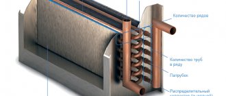
A heater (duct heater) is a universal device that transfers thermal energy from the heating element to the supply air. The device works as a heat exchanger. It consists of pipes through which air masses circulate. In pipes, thermal energy is transferred from one carrier to another.
When air enters the unit through the grille, the masses are heated due to heat exchange from the pipes. Next, the fan blows the device and supplies heated air through the diffuser into the room. To ensure that the device operates silently, special sound-absorbing elements are used. When the installation is turned off, the valves block the access of cold air from the street to the system.
The heater cannot work without a piping system. For its operation, control units will be required that perform the following functions:
- Work control. The parts ensure constant operation and report failures.
- Ensuring uninterrupted operation of the heat exchanger. Emergency notification.
- Temperature control and regulation. The temperature must be within the design range for uniform heating.
- Preventing icing.
A water heater cannot operate without auxiliary units.
The system includes the following elements:
- Shut-off valves. These are taps for shutting off the coolant flow, which are made from durable materials (steel, brass). Selected according to the power of the device.
- Check valves. They are a barrier to the outflow of fluid. The choice is made according to the diameter of the pipelines.
- Drive and control valves. They are the main and most important part of the harness.
- Pressure gauge, thermometer.
- Air bleed and drain valve.
- Balancing valve.
- Pump.
- Filter. A mesh with a cell size of 500 microns is used.
The installation of the system is carried out by specialists in accordance with existing standards specified in SNiP, SP and GOST. You first need to create a drawing of the heater for the correct connection.
Advantages and disadvantages
Despite all their convenience, air heaters consume a large amount of electricity
Water and steam heaters designed for heating industrial premises are extremely profitable because they do not require additional investments. Financial resources are spent only on the purchase of the device. Their advantages:
- quickly achieving the desired air temperature;
- simple installation;
- safety;
- reliability;
- possibility of adjusting the heating level.
Disadvantages include:
- use in rooms with positive air temperatures;
- impossibility of using for heating apartments;
- equipment is required to provide air traction;
- If the coolant supply stops, the system stops working.
The last point is also true for electric heaters, but only concerns power outages.
Controller
- temperature sensors: air temperature in the duct
- return water temperature at the outlet of the heater
- fault on the internal overheating sensor in the air heater
Typical scenarios:
- In the “electric heater” operating mode: smooth regulation using a PWM signal with a period of 4 seconds.
- smooth start with warm-up
- smooth shutdown with blowing of the electric heater at low fan speed
- the settings for the return water temperature are adjusted: “temp. working" (+30 °C), "temp. duty" (+20 °C), "temp. threat of freezing" (+10 °C), "temp. warming up" (+45 °C)
- at system startup, if the return water temperature does not reach “temp. warming up", then the electric heater is connected
Interesting features of the Controller that I planned to use:
- the ability to adjust the temperature using an external room temperature sensor with a cascade coefficient, which shows by how many degrees the air temperature in the duct should be changed when the room temperature changes by 1 °C
- for air heaters from several sections (I have three sections of 1 kW each) step switching is provided: one step smoothly plus three steps discretely
Types and characteristics
In a water heater, water performs the functions of a coolant
The devices in question operate on ordinary water and other types of energy carriers. According to the type of energy source used, the following types of heating units are distinguished:
- water;
- steam;
- electric.
A water air heater is a common type of device, characterized by safety, efficiency and ease of maintenance. The function of the coolant in it is performed by hot water coming from the local hot water supply network or from the boiler. Water heaters for fresh air ventilation are a very profitable option, characterized by minimal maintenance and operating costs. The only problem with a water heater is the difficulty of installation associated with the installation of centralized or local heating pipes. This connection does not allow you to quickly move the device to a new location.
An air-steam heater is a complete analogue of water models, differing from them only in the type of coolant used. The structural difference is manifested in the greater wall thickness of copper tubes (2 mm versus 1.5 mm for water samples). This is explained by significant pressure in the system, forcing the structure of the outlet channels to be strengthened.
Technical characteristics of water heaters
An electric heater installation does not require a coolant, since the energy source in it is a mains voltage of 220 Volts with a frequency of 50 Hertz. Easy connection of electrical units ensures mobility and ease of use. Their disadvantage is significant energy consumption, which limits the use of devices. They are in demand in situations where local heating is required during one-time work (as emergency or temporary heat sources).
The main characteristics of air heaters include:
- water temperature at the inlet and outlet of the device;
- the speed of movement of the carrier along the heating channels;
- air temperature at the outlet of the unit;
- operating pressure in the system.
When describing devices, the maximum operating temperature of the liquid circulating in the nozzles and the service life of the product are also indicated.
Basic equipment of heat supply units. Selection and calculation
The heat supply units of air handling units made according to different schemes, as a rule, include identical equipment. Such units differ only in the installation location, the saturation of the reinforcement and the selection method.
When selecting equipment for heat supply units, there are several general rules and recommendations:
- When choosing a particular type of valve, you should carefully check the technical characteristics of both the maximum operating pressure and the maximum temperature.
- It is highly not recommended to purchase ready-made mixing units that are selected based on average conditions without taking into account important parameters such as free pressure drop in the system, type of coolant, flow rate, type of heat source, the need for frequency regulation, and so on.
- The diameter of shut-off valves, as well as check valves and mud traps must be no less than the diameter of the pipelines.
- The diameter of the heating system pipelines is determined as a result of hydraulic calculation based on the calculated (required) coolant flow rate, type of coolant (water or low-freezing liquids) and pipeline material. In no case should the diameter of the heating supply units be selected based on the connecting ports of the heater. It is selected ONLY BY CALCULATION!
Shut-off valves
It is necessary to shut off the water flow in cases of emergency stops of the heating system, for example, to eliminate a leak, to carry out service or inspection work, etc. As shut-off valves, steel or brass ball valves (preferably full bore) or flanged valves are used.
For heat supply units with a pipeline diameter of up to 40 mm inclusive, it is customary to install threaded shut-off valves, and flanged valves over 50 mm.
To facilitate the installation or dismantling of assemblies, threaded fittings should be provided with union nuts, otherwise called “American or socket nuts”.
Check valves
Check valves are used in control units to prevent water from flowing back into the heating system if control valves are opened or closed. Or this is possible when the heating system is not balanced, a large number of units are installed in the system and when the coolant flow changes, pressure may occur on each other. Therefore, check valves are installed on the return pipeline and on the jumper of the heating supply unit.
Control Valves and Actuators
Two way valve.
A two-way or three-way control valve is the main actuator, which, by changing the flow rate or by mixing coolants, allows you to regulate the power of the air-handling unit heater depending on the heating demand of the installation. Another important function of the valve is to prevent the coolant from “freezing” when the units operate in winter. When the automation receives a signal about the critical temperatures of the coolant and air after the heater, the drive opens the control valve to the maximum flow.
Three-way valve.
The valve is selected based on the determination of the throughput coefficient Kv, which means how much coolant flow will pass through the valve in the open state with a loss of 10 meters of water column.
,
where G is the estimated water flow, m3/h; ∆p - actual pressure drop across the valve, bar Ƥ - coolant density.
The size of the control valve cannot be selected according to the diameter of the pipeline or heater ports. The smaller the Kv or valve diameter, the higher the speed of response to changes in air or heating network parameters will be, that is, the system will not be inertial.
In heat supply systems of air supply units, as a rule, two and three-way valves are used. Two-way valves work only in systems with changes in coolant flow, and three-way valves either act as mixing valves or work to separate heat flows.
Measuring fittings: pressure gauges and thermometers
Measuring equipment
Pressure gauges and thermometers are necessary tools for visual monitoring of the performance of the heating system. Thermometers are usually installed on the supply and return pipelines directly next to the heater. Pressure gauges are mounted on the pump group to monitor the operation of the pump and visually determine the difference created. Pressure gauges are also installed before and after the sump tank - to determine the degree of its clogging, and on the supply and return pipelines of the heating network in front of the piping unit - to control the free drop necessary for the full operation of the control valve.
Air bleed valves and system drain taps
Automatic air release valve
To bleed air after filling the system and during operation, it is recommended to install automatic air bleed valves in the piping units. They are conveniently mounted on special ports embedded in the heater coils in the upper part of the housing or at the highest point of the control unit pipelines.
Taps for emptying heaters and draining a section of the heating system should be installed at the lowest point of the control unit, or at the bottom of the heater.
Balancing valves
Balancing valve
If the heat supply system has several air supply units operating in their own independent mode, then the heat flows in the pipelines will not be constant and may differ significantly from each other. To prevent pressure on each other from the coolant side, balancing valves are provided. Their main and main function is to throttle excess pressure and equalize the distribution of water flow between heaters in accordance with needs. Balancing valves installed on the return pipelines hydraulically link the heaters to each other.
The selection of valves is carried out by analogy with the selection of control valves, taking into account the Kv coefficient. The initial data for determining the valve size is the excess pressure drop that the balancing valve must absorb and the calculated flow rate in the network section.
Circulation pump
Circulation pump
The circulation pump of the internal circuit of the piping unit is designed to ensure constant circulation of water in the heater. This will minimize the risk of the heater “defrosting” at low outdoor temperatures. But the main purpose of the pumps is to overcome hydraulic resistance in the regulated area, that is, on all functional elements of the mixing unit, unloaded from the pressure of the heating network.
The regulated section usually means a heater, pipelines, shut-off and balancing valves, check valves and a sump. The control valve may be part of the regulated section, depending on the adopted heater piping scheme. If the control valve is installed in the piping unit in such a way that the coolant circulates in the internal circuit through the jumper of the valve itself with the direct port closed, then the valve is part of the circulation circuit. In such cases, the pump pressure is determined as the sum of the hydraulic resistance of all elements of the regulated section. It should be remembered that in the case when the coolant in the heating system is not water, the hydraulic resistance of all elements of the regulated section and the calculated flow rate should be adjusted depending on the viscosity and density of the coolant. Hydraulic losses on mud pits should be taken into account with a margin of 50% clogging.
If the control valve operates on a difference in the heating network (diagram No. 3), then the pressure loss on the valve is not taken into account when calculating the pump head.
When calculating the friction resistance of pipelines, it is imperative to take into account all pressure losses at branches, corners and turns. It is also necessary to take into account the roughness of the pipeline walls in accordance with the selected material.
All pressure losses on the elements of the piping unit should be determined only at the operating flow rate of the coolant, and not in accordance with the maximum flow rate of the heater that it is capable of passing.
The selection of circulation pumps is made according to the technical catalogs of manufacturers in accordance with operating points (calculated water flow and required pressure). The most common type of pump in units are three-speed glandless pumps. In cases where a smooth change in flow rate in the supply ventilation circuit is required, pumps with a built-in frequency converter are used.
Sump
Sump
Mud filters are filters for mechanical cleaning of coolant, usually with a mesh size of about 500 microns. In old heating systems, heating water contains a lot of suspended particles, sand or scale. All these contaminants can damage control valves and circulation pumps. Therefore, installing mud collectors directly in front of the equipment is a prerequisite for maintaining operability and warranty.
Quality of work: air handling unit heater piping unit
There are 2 methods of installing the device, which are determined by the heat exchange diagram. If we talk about natural ventilation, the heater should be located in the basement near the water intake point. With a forced ventilation system, the device will begin to function correctly only with the correct installation of the heater module piping unit.
These devices allow you to regulate the temperature level of the heat exchanger:
- Bypass;
- Eyeliner;
- Cleaning filter;
- Pump;
- Ball Valves;
- Thermometers and pressure gauges;
- Electric valve.
If we are talking about installing a piping unit with a rigid liner, communications will be carried out using steel pipes. Sometimes flexible connections with corrugated hoses in the system are also used for installations. The location of the node is determined in advance. Tying a knot does not involve any serious expenses.
Connection diagrams
Scheme with two ventilation circuits
To effectively heat the incoming air using a heater, it is necessary to make the correct connection. There are several installation schemes, which include:
- One ventilation circuit and one heater. This is the simplest scheme in which one heating device is located at the inlet or any other section of the channel. This connection is used for seasonal heating and does not have a backup heat source.
- Two ventilation circuits and several heaters. This is a more complex scheme, suitable for installation in complexly shaped rooms. Suitable for year-round use. There are several tying knots. The first circuit is used for heating in autumn-winter, and the second for summer. Due to the large number of devices, the system can operate continuously even in the event of an accident at one of the piping units.
Ventilation diagram with a heater
The classic piping unit includes the following elements:
- Circulation pump. It is used in water systems and disperses liquid through pipes.
- Compressor-condensing unit. It is used as an external unit in the cooling system piping.
- Temperature and pressure control devices.
- Locking mechanisms.
- Bypass.
- Filter.
- Two-way or three-way automatic valve.
- Tubes, connectors and other parts to connect the mixing unit for ventilation.
The connection diagram for the piping unit can be made using rigid and flexible connections. Rigid liner is the simplest connection option using metal pipes. Suitable when the exact location of the heater is already known. Flexible liner is the most complex and is made using corrugated pipes.
Temperature regulation
Temperature control is the most important task of the system. There are two ways to adjust:
- Quantitative. This is an outdated method in which the temperature directly depends on the volume of coolant.
- Qualitative. A more efficient method in which the coolant is consumed linearly. This is done using a three-way valve and pump. There is no possibility of leakage.
Experts use the second method. It is compatible with any heater connection scheme.
Ventilation system
Piping with a two-way valve
The choice of the optimal ventilation scheme is influenced by the required temperature, heating intensity, coolant source, and pressure difference. There are several systems:
- Piping of the ventilation unit using a two-way valve. It is placed at the entry point without an additional heat exchanger. As a result, the valve acts as an intermediate buffer and dampens the pressure of the water flow. The disadvantages of the scheme include the risk of freezing at subzero temperatures. Pump installation required.
- Using a three-way valve. The result is two strapping systems. In the first case, the water flows are separated, and in the second, they are mixed. The scheme is used in autonomous heating networks.
Any scheme requires installation of a hood. By maintaining a balance between incoming and outgoing air flows, the calculated temperature in the room is maintained.
Supply ventilation with water-heated air
The air is heated to the required temperature by a water heater. It is presented in the form of a radiator with tubes containing coolant. The pipeline has fins that increase the area of contact with the circulated air.
The principle of operation of the system is as follows: the coolant heats the tubes to the desired temperature, they transfer heat to the fins, which in turn heats the air. Thus, heat exchange takes place.
Supply ventilation with water heated air is much more profitable than heating using electricity. On the other hand, there is water inside the water heater, so there is a risk of it freezing with minimal radiator operation.
The power of such a device is adjusted using electrical and plumbing components.
- Area with controller and temperature sensors. Servomotor that controls the valve.
- The mixer is responsible for heating the water in the heating equipment to the required temperature.
The electrical component will control the plumbing unit. It is enough to set the required air heating temperature, and the system will execute this program.
DIY mixing unit
When assembling yourself, you need to consider the following features:
The actuator on the control valve must not be turned down; The axis of the circulation pump should not be directed downward, like the electrical box; The sump of the coarse filter should be directed downwards.
Following the above rules, the process of assembling the mixing unit begins with connecting the components. When connecting, you need to focus on the diagram and, depending on the purpose, follow the connection sequence. The joints are sealed using waterproofing agents: fum tape, tow, or thread
It is important not to overtighten the connection to avoid cracks and chips. A fully assembled unit requires a test connection
If water leaks, the leak must be eliminated by reassembly. A properly assembled unit will last a long time.
Rigid and flexible distribution units
There are two types of thermo-mixing strapping structures for connecting devices and equipment:
- hard - plastic or metal (steel) pipes are used;
- flexible - when assembling and installing the piping unit, corrugated hoses are used.
The hard version is the most common. This is due to the ease of installation of the structure and low cost.
A mixing unit with flexible connections is used when installation space is limited. This option has greater functionality, but is more expensive.
Source
Heat energy consumption systems: air supply unit control unit
There may be several systems that are combined with a heater. This includes a ventilation system, radiator heating, and also floor heating and a thermal curtain. We can look at each in general terms.
Systems combined with a heater:
- Ventilation system - the maximum temperature of the heat exchanger is influenced by the technical parameters of the equipment; the heater must be protected from freezing. That is, in winter, when subzero air is “supplied,” you cannot reduce energy consumption or coolant temperature lower than determined by the system.
- Radiator heating - there is a strict limitation on the temperature of the coolant. But it can decrease as much as desired, even until the operation stops, and this is the main difference between this item and the ventilation unit.
- Underfloor heating differs from radiator heating in that the maximum coolant temperature is limited. Usually it does not exceed 50 degrees.
- Thermal curtain – its working time does not exceed a couple of minutes. The installation location is always located away from the heating source. Usually this is a sub-ceiling location.
As for efficiency, the device of the fan heater should be given first place. In this case, less energy is consumed. But the final choice is yours.
Basics of operating water units
The IP degree in rooms with high humidity must be at least 66
In order for the ventilation heater to serve for a long time and perform its functions properly, you must adhere to the following rules:
- monitor the quality composition of the air in the room being served - the requirements for this indicator can be found in GOST 12.1.005-88;
- installation of the system should be carried out in strict accordance with the attached instructions and taking into account the manufacturer’s recommendations;
- do not increase the coolant temperature above the limit value (+ 190 °C);
- during operation, do not exceed permissible pressure standards (about 1.2 MPa);
- after prolonged cooling of the serviced room, warm it up gradually (by about 30 °C per hour);
- Make sure that the ambient temperature does not fall below 0°C, which can lead to rupture of the heat exchanger tubes.
If the heater is intended to be used in a room with a high level of humidity, the degree of dust and moisture protection of the device should not be less than IP66.
It is not recommended to repair the device yourself if it breaks down. You need to contact a service center and entrust the restoration of an expensive device to professionals.
Before purchasing, it is advisable to determine the power consumed from the network.
Power calculation
Before you start choosing a heater, you should calculate the main indicators, such as the power and temperature of the air flows at the outlet of the installation. In addition, it is necessary to take into account a number of characteristics depending on the use of different types of power and the number of phases. So, when connecting an electric heater with a power of 5 kW, it is necessary to arrange a three-phase connection.
In addition to electrical calculations, it is necessary to find out the temperature of the supply flows when using a heater of a particular power. The formula used for calculation is T=2.98xP/L, where L means the system performance, and P is the power of the electrical element. Standard indicators for the power of air heaters for apartments and private houses are considered to be values from 1 to 5 kW, despite the fact that the power of devices installed in the ventilation systems of large industrial enterprises is 5-50 kW.
ESBE DRIVES (SWEDEN)
Unique precision and functionality. Possibility of switching to manual mode. Power supply 24V DC/AC current, 50/60 Hz. Control signal 0-10V, 2-10V, 0-20mA, 4-20 mA.
| Name | Specifications |
| ESBE ARA 659 | 24 V, 0-10 V, 6 Nm |
| ESBE 92P | 24 V, 0-10 V, 15 Nm |
| ESBE 95 | 220 V, ON/OFF, 15 Nm |
Options for adjusting temperature during heating process
Diagram of a heater piping unit with a three-way valve
The heating control process is of two types: qualitative and quantitative.
The use of quantitative heating control is not always advisable, since the amount of coolant constantly changes during operation.
High-quality heating regulation implies operation of the heater using the same volume of coolant.
There are several advantages of the high-quality heating principle:
- stable linearity of the process is ensured in any position of the control valve;
- freezing of the unit can be prevented or reduced by ensuring a constant flow of water;
- if there is a special pump and a three-way valve, then in this case the qualitative principle of heating control is used.
Distribution units with two- and three-way valves
The most common is the circuit diagram of the heater piping unit of the air supply unit with an electrically dependent three-way mixing valve. This design allows you to mix the hot coolant with the exhaust water, changing its temperature in accordance with the specified parameters.
The air supply unit piping unit, the circuit of which includes a two-way valve, costs less than a three-way valve. However, it has a significant disadvantage - limiting the volume of the working medium passing through the heating installation.
Water heater and supply ventilation system
Many words like “mixing device”, “cooler device” and “connection of air heaters” confuse the inexperienced user. He has only heard about the structure of the freon circuit, and he understands quite roughly what the piping units are. To learn more about heat appliance systems, you can “learn” from disassembling such a unit as a water heater.
If we talk about the quantitative option, then a changing heat consumption is inevitable. This is not the best option, of course, which is why today the so-called good regulation principle is used. It ensures linearity of the process, no matter what position the control valve occupies. This principle also implies excellent resistance to possible freezing of the heating device.
A good control principle uses elements such as a centrifugal pump and a three-way rod valve. They allow you to increase the efficiency of the heater and piping. They also guarantee that there can be no leaks on the floor from the steam appliance.
How is the heating of the heater regulated?
In order to control the heating procedure occurring in the device piping unit, you can use one of two possible methods:
- quantitative;
- quality.
If you choose quantitative control of the system’s operation, then you will face an inevitable and constantly “jumping” coolant consumption. Such a method can hardly be called rational, and this is one of the reasons that in recent years people have more often resorted to another principle of control - qualitative. Thanks to it, it became possible to regulate the operation of the heater, but the amount of coolant does not change at all.
In addition, if you regulate the system using the quality principle, then the control is guaranteed to remain linear, regardless of what position the control valve is in.
Important! Quality control has one more advantage - this way the heater will be maximally protected from possible freezing, since water will constantly flow into it. All this became possible only due to the fact that a water pump is installed in the heater circuit. There is a flow of water in the circuit, which will not depend on any external influences
In addition, quality control involves the use of a three-stroke rod valve and a specialized pump. All these parts built into the device’s piping have significant advantages that increase the efficiency of the heater and the entire system as a whole:
There is a flow of water in the circuit, which will not depend on any external influences. In addition, quality control involves the use of a three-stroke rod valve and a specialized pump. All these parts built into the device’s piping have significant advantages that increase the efficiency of the heater and the entire system as a whole:
All this became possible only due to the fact that a water pump is installed in the heater circuit. There is a flow of water in the circuit, which will not depend on any external influences. In addition, quality control involves the use of a three-stroke rod valve and a specialized pump. All these parts built into the device’s piping have significant advantages that increase the efficiency of the heater and the entire system as a whole:
- The regulation valve is located in the place where the coolant enters the heater. If you compare this to a two-stroke device, it controls the entire mixing procedure. If the circuit is in a closed state, then internal circulation occurs; if it is open, then the coolant does not recirculate. If such a design is installed with a rod, this will not only increase the service life of the valve itself (which, as is known, very quickly becomes unusable in products that do not have rods), but will also increase heat transfer.
- The motor of a centrifugal circulation pump is “wet”; in other words, it operates while completely immersed in water. Consequently, the bearings of the device, as well as other elements, are constantly lubricated with water, so there is no need to use any kind of seals. If the heater piping is equipped with such a pump, then leakage is completely eliminated even in cases where the pump is broken or has completely exhausted its service life.
What it is?
The heater for supply ventilation is made in the form of a heat exchanger, in which the air masses coming from the street are heated to the desired temperature. The device is a separate device that is either installed into the system independently or is already built into the ventilation unit. This depends on the design features of the ventilation unit, and is determined by the technical capabilities of installation and the personal preferences of the consumer.
In prefabricated modular systems, all elements are purchased separately and then connected into a single ventilation network, while in monoblock installations the elements are already installed and adjusted. In addition to heaters, the ventilation unit includes a filtration and humidification system, which allows you to obtain air at the entrance to the room that meets strict sanitary and hygienic standards. Some modern systems are additionally equipped with devices for disinfection and ionization of air flows.
Types of air heaters used in supply-type ventilation systems
The choice of such devices for organizing supply ventilation is usually based on several main factors, which include productivity, total area of the room, equipment power, as well as the climatic features of a particular area. Taking into account all the listed characteristics, the following types are used:
- electric heaters for supply ventilation - the use of this type of heater is considered the most economically justified, based on the fact that the electric heater does not require complex communications (it is enough to connect the device to the power supply) and is equipped with special heating elements for the most efficient heat exchange, which convert electrical energy into heat.
- water heaters for supply ventilation - their main purpose is to heat air in ventilation systems with a round and rectangular cross-section, therefore they are successfully used for heating cottages, shops, large complexes, warehouses and premises, including livestock farms.
The use of electric heaters is effective when the area of the ventilated room is within 100-150 m2.
The main advantages of such heaters are the ease of installation and their general availability, but the disadvantage is the high level of energy consumption. Water heaters are quite practical, cost-effective and reliable devices for efficiently heating large volumes of air (more than 150 m2) and do not require constant or frequent maintenance. The quality of their work depends entirely on the presence of automatic control.
When installed at the top point with a downward direction, a water-type heater is able to quickly and easily equalize the temperature of the air mass of the room, thanks to the equipment of this type of heat exchanger with a special thermostat. For better heating, such devices can be combined into a single structure.
