Supply and exhaust ventilation works by consuming and processing outside air. In conditions of negative temperatures and long winters, the air flows must be heated, because if you let them in directly, the microclimate inside the building will become unsuitable for humans. The supply air is heated by a heater. The efficiency of the ventilation system directly depends on it. Therefore, the piping of the supply air heater must be carried out in compliance with all norms and rules and only with high-quality materials. The technical part is being developed in the project.
Water heater and supply ventilation system
Many words like “mixing device”, “cooler device” and “connection of air heaters” confuse the inexperienced user. He has only heard about the structure of the freon circuit, and he understands quite roughly what the piping units are. To learn more about heat appliance systems, you can “learn” from disassembling such a unit as a water heater.
If we talk about the quantitative option, then a changing heat consumption is inevitable. This is not the best option, of course, which is why today the so-called good regulation principle is used. It ensures linearity of the process, no matter what position the control valve occupies. This principle also implies excellent resistance to possible freezing of the heating device.
A good control principle uses elements such as a centrifugal pump and a three-way rod valve. They allow you to increase the efficiency of the heater and piping. They also guarantee that there can be no leaks on the floor from the steam appliance.
Pros and cons of using
If the enterprise has its own heat supply system, the use of air heaters for supply ventilation of production premises is as cost-effective as possible.
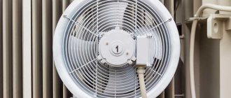
A set of water fan heaters for servicing a warehouse. Air heaters with an air flow rate of 5200 m³/h and a coolant temperature of + 130 ºС heat the air and maintain the set temperature
Advantages of devices connected to a centralized system:
- simple installation, no different in complexity from installing heating pipes;
- rapid heating of a large room;
- safety of operation of all components;
- possibility of adjusting the flow of heated air;
- strict industrial design.
But the main advantage is the absence of regular financial investments - payment occurs only when purchasing new equipment.
Current prices for KSK bimetallic water heaters produced by Novosibirsk, which manufactures heating equipment. The final price depends on the basic configuration and technical characteristics
The main disadvantage is considered to be the impossibility of using water models in everyday life, especially in urban housing. An alternative is to use electrical appliances.
Another nuance concerns negative temperatures: the equipment must be installed in rooms where the minimum threshold does not fall below 0 °C.
There are practically no wearing parts in the design of the water heater. They rarely fail and require serious repairs, which should also be included in the “treasury” of equipment advantages
Design Features
Essential elements
- Air intake grille. It has both a decorative purpose and serves as a barrier to dust and other particles contained in wind masses.
- Valve. When ventilation is turned off, the valve blocks the passage for fresh air, creating an insurmountable barrier. In winter, it can block a lot of air flow. You can automate its operation using an electric drive.
- Filters clean wind masses. They need to be changed every six months.
- Water, electric heater, which performs the function of heating the air.
- For small buildings it is advisable to use an electric heater. In large rooms it is better to use a water heater.
Principle of operation
A fan, a heat exchanger and a convector - this is what a water heating device looks like in general terms.
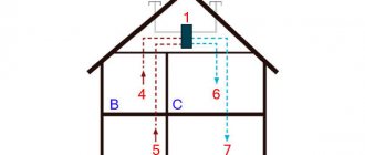
The operating principle of supply ventilation is as follows:
- The air flow enters special air intake grilles that prevent insects, small objects, birds, and animals from entering the ventilation channels.
- Filters clean the air from contaminants, harmful substances, and dust.
- The heater, using heat supplied from the water main, heats it to the desired temperature.
- The recuperator mixes the newly supplied air with the heated one.
- The fan supplies heated air masses into the room, and the diffuser distributes them evenly over the entire area.
- Sound absorbers reduce the sound power of a running installation.
- If the air supply is cut off, valves are activated to prevent cold air from entering the room.
An example of using a VOLCANO air heater in a tire repair shop (water temperature +90 ºС)
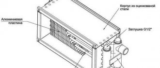
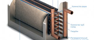
The heater, which does not have its own heater, consists of two main elements:
- A heat exchanger, the design of which is represented by a system of metal tubes - water coming from the general heating system reaches the required temperature here.
- Built-in fan that disperses heated air flow throughout the entire area.
Installation and connection features
Installation work, connection, starting the system, setting up work - all this must be carried out by a team of specialists. Installing a heater with your own hands is possible only in private homes, where there is no such high responsibility as in industrial premises. Basic operations include installation of the device and controls, connecting them in the required order, connecting to the coolant supply and removal system, pressure testing, and test run. If all components of the complex demonstrate high-quality operation, then the system is put into permanent operation.
Advantages and disadvantages
Despite all their convenience, air heaters consume a large amount of electricity
Water and steam heaters designed for heating industrial premises are extremely profitable because they do not require additional investments. Financial resources are spent only on the purchase of the device. Their advantages:
- quickly achieving the desired air temperature;
- simple installation;
- safety;
- reliability;
- possibility of adjusting the heating level.
Disadvantages include:
- use in rooms with positive air temperatures;
- impossibility of using for heating apartments;
- equipment is required to provide air traction;
- If the coolant supply stops, the system stops working.
The last point is also true for electric heaters, but only concerns power outages.
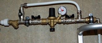
What does the heater wiring diagram look like?
The operating principle can be outlined in general terms. Water, that is, a high-temperature coolant, enters the heater itself, first passing through a settling filter, and then an important three-way valve. To ensure that the water flows at the required pressure, a small circulation pump is used. The water, already cooled, enters the piping, goes to the boiler, and some of its volume also enters the valve.
As for the three-code valve, it necessarily comes with the heater piping and is considered an important control component. It maintains a constant temperature and volume of coolant entering the heating device. When the hot water temperature rises, this valve reduces the water supply while the chilled water supply increases. It turns out that the piping of the heat exchanger, without changing the water pressure in the system, changes its temperature.
Take note:
- The control valve is the main participant in the heater piping; it operates in auto mode and is controlled by an electric drive. The harness includes various sensors; they send signals to the electric drive, due to which the temperature is regulated and maintained at the desired level.
- Design of the piping - there may be standard wiring diagrams that, in principle, are connected to the heater, but they will still have to be adjusted to the device. However, the harness is usually designed for each specific device.
- Options for placing harnesses - this can be either vertical or horizontal. But not every harness can operate in every position. Therefore, the location of the piping is determined when designing the ventilation unit. Otherwise, incorrect operation of the heater piping is guaranteed, or it may even refuse to work at all.
The heater piping can be built according to several schemes. In practice, a standard circuit is more often used, the design of which is simple and the reliability is quite high.
The heat source determines the choice of control unit circuit
At the design stage of ventilation systems and heat supply systems for air handling units, the choice of circuits and type of heater piping units directly depends on the heat source itself.
For example, individual boiler houses, as a rule, are not demanding on the temperature of the returned coolant, but the difference in the heating network must be constant. That is, the control valve should not be blocked from the heating network side, or a jumper should be provided to allow water to flow through it to the return line when the direct port of the valve is closed. Such schemes mainly include the heater piping unit, made in the 2nd version (diagram No. 4). Thus, water heating boilers will operate at a constant flow rate and will not overheat if there is a shortage of coolant.
The heater piping unit with a three-way valve without jumpers can be used for central heating with an independent connection through a plate heat exchanger. This is due to the low limiting parameters of the coolant: maximum temperature (for brass control valves this is about 110°C, and for cast iron valves 90-95°C) and operating pressure, as a rule, not exceeding 10 atm. In central heating networks, peak temperatures of about 150°C and pressure surges of up to 16 atm are possible. Since the direct port is closed when the three-way valve operates, there will be a variable flow rate in the heating network. The main requirement is the installation of a frequency converter on the network pump, which will adjust the operation of the system to changing parameters. This scheme is also applicable for working with boiler installations if all the above requirements are met.
Rules for operating the heater
For the correct and uninterrupted operation of heaters for supply ventilation systems, it is important to follow the following operating rules:
- It is necessary to maintain a certain air composition in the building. Requirements for air masses in premises for various purposes are listed in GOST No. 2.1.005-88.
- When installing, you must follow the manufacturer's recommendations and adhere to installation technology.
- You cannot supply coolant with a temperature above 190 degrees to the device. For some models this threshold is lower, as stated in the technical documentation.
- The pressure of the liquid medium in the heat exchanger must be within 1.2 MPa.
- If you need to heat the air in a cold room, then it is heated smoothly. The temperature rise within an hour should be 30 degrees.
- To prevent the liquid from freezing in the heat exchanger and breaking the tubes, the surrounding air masses around the device must not be allowed to cool below zero degrees.
- In rooms with high humidity levels, units with a degree of protection of IP66 and higher are installed.
Manufacturers of water heaters do not recommend repairing them yourself. It is better to entrust this work to the service center employees
It is equally important before purchasing to correctly calculate the power of the device so that it provides proper performance and does not run idle
Heater thermal power reserve
9. Determine the thermal performance reserve of the adopted heater(s). ((q - Q) / Q) • 100 q - actual thermal power of the selected air heaters, W; Q is the calculated thermal power for heating the required volume of air, W. The actual thermal performance of the adopted steam-air heater must be greater than the calculated one. The range of the permissible percentage ratio of actual and calculated power, according to various sources, can be from 96 to 120 (from - 4 to 20)%. In any case, you need to strive for the closest possible equality of power (actual performance = 100 - 110% of the calculated one). If, during the calculation, the difference is greater than the above figures, a recalculation should be made.
An example of calculation and selection of a KPSk heater. Step-9
Select a suitable KPSk heater for heating 6500 m³/hour from a temperature of -28°C to +29°C. The coolant is dry saturated steam with a pressure of 0.1 MPa. 9. We calculate the discrepancy between the actual and calculated thermal power of the selected heat exchangers ((104653 - 133426) / 133426) • 100 = -21.6% - for the KPSk 2-10 air heater ((150642 - 133426) / 133426) • 100 = 12.9% - for heater KPSk 3-10 ((188874 - 133426) / 133426) • 100 = 41.6% - for heater KPSk 4-10 104653, 150642, 188874 - actual thermal power of the selected steam heat exchangers, W; 133426 — calculated thermal power for heating a given volume of air, W. -21.6, 12.9, 41.6 — thermal performance reserve of the selected air heaters. Of the considered models of heaters KPSk number 10, only the three-row air heater KPSk 3-10 corresponds under given conditions to the recommended ratio of actual and calculated power.
Types of thermal energy consumption systems
There may be several such systems compatible with the heater. Let's look briefly at each.
Ventilation system
It is characterized by the fact that the maximum temperature of the coolant is directly influenced by the technical parameters of the existing equipment. The problem with regards to how to choose the right piping unit is the need to protect the heater from possible freezing. In winter, when the air is supplied at sub-zero temperatures, the temperature of the coolant cannot be reduced or the energy consumption lower than what the system requires.
Radiator heating
In this case, the coolant temperature is strictly limited. For single-pipe structures it is 105 degrees, for two-pipe structures it is 95 degrees. But the temperature of the carrier can decrease indefinitely, until the operation stops altogether, which distinguishes heating from a ventilation system. Here, all elements are in direct contact with the air in the building, and due to the fact that it also has heat-storing characteristics, the building cools quite slowly. In this case, the time period during which a decrease in temperature is possible is established for each individual case.
Underfloor heating
The heat consumption here is the same as in the previous version. The only difference can be considered that the temperature of the coolant (maximum) is limited. In most cases this is no more than 50 degrees.
Thermal curtain
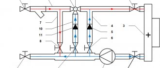
The heater piping for thermal curtains differs significantly from all previous options, so we will consider it in more detail. First of all, this relates to the peculiarities of the operation of the thermal curtain itself: almost all the time the curtain “rests”, waits, but its working time often does not exceed two to three minutes. Moreover, the installation site is always located far from the heating source. In most cases, this is a place under the ceiling, and there, accordingly, hypothermia often occurs, as well as drafts. Below is a diagram with adjustment elements that are suitable for this case.
The system is equipped with special ball joints necessary to disconnect it from the described curtain or from the thermal route. There is also a coarsely cleanable filter that protects the device; an adjustment valve that prevents the entry of solid particles, which, in turn, can extremely negatively affect the performance of the system in general. There are two more valves:
- Regulating-shut-off.
- Regulating, equipped with a special drive.
Each of them is designed to provide maximum fluid flow in operating mode, and minimum flow when “inactive”. In order for the valve drives of such a piping intended for thermal curtains to be provided with proper power, a single-phase voltage of 220 volts should be connected.
Finally, all the elements that make up the heater piping in this case are necessary not only to regulate the temperature in the building, but to protect the device itself from temperature changes and pressure “jumps” that often occur in the heating supply network. If you install mixer blocks, the heating circuit will reach the operating mode that is necessary for the controlled parameters.
Note! Ventilation works more efficiently in this regard, since less energy is consumed
Basic diagrams of control units
There are at least several basic heater piping schemes, which have fundamental differences in terms of the chosen control scheme and heat supply source. There is no clear answer as to which of the schemes described below is correct; it all depends on a large number of factors (heat supply source and its capabilities and coolant requirements, already installed network equipment, the value of the free pressure drop at the entrance to the building, etc.).
a two-way linear control valve is installed as a control element , which absorbs the excess difference at the connection point and performs the main function of limiting the flow of water through heater. But in order to ensure protection against freezing of the air heater, a circulation pump is installed on the internal circuit of the air heater, which ensures constant flow through the installation through an additional jumper. This is a classic method of quantitative zonal control at each air supply unit.
No less common are heat supply schemes for heaters with installed three-way valves . These circuits can operate in different control modes depending on the position of the valve and the location of the jumper insertion.
Three-way valves can operate in water flow separation mode or as a mixing element (diagram No. 4). If the valve is installed in such a way that, depending on the heating demand of the installation, port A (from the heating network side) opens or closes, and the coolant circulates through the clan bypass (ports B and AB), then the most common quantitative control scheme takes place. Its use, as a rule, is limited by the maximum pressure drop in the central heating system, therefore it is most often used in autonomous heating systems. But when designing such a scheme, it is necessary to take into account that the flow rate in the heat supply system or at the heat source is not constant, therefore the network pumping equipment must be equipped with frequency converters.
If it is necessary to ensure a constant flow rate from the heat source, then a jumper with an installed check valve and balancing valve should be added to the previous diagram in front of the valve (diagram No. 5).
If the jumper and valve are swapped in the circuit, and water is circulated in the internal circuit through the jumper, then the pressure of the circulation pump in this case will be less by the amount of hydraulic resistance of the valve. The coolant flow from the heating network will remain constant, and the valve will operate on a free pressure drop (diagram No. 6).
How is the heating of the heater regulated?
In order to control the heating procedure occurring in the device piping unit, you can use one of two possible methods:
- quantitative;
- quality.
If you choose quantitative control of the system’s operation, then you will face an inevitable and constantly “jumping” coolant consumption. Such a method can hardly be called rational, and this is one of the reasons that in recent years people have more often resorted to another principle of control - qualitative. Thanks to it, it became possible to regulate the operation of the heater, but the amount of coolant does not change at all.
In addition, if you regulate the system using the quality principle, then the control is guaranteed to remain linear, regardless of what position the control valve is in.
Important! Quality control has one more advantage - this way the heater will be maximally protected from possible freezing, since water will constantly flow into it. All this became possible only thanks to the fact that a water pump is installed in the heater circuit
There is a flow of water in the circuit, which will not depend on any external influences. In addition, quality control involves the use of a three-stroke rod valve and a specialized pump. All these parts built into the device’s piping have significant advantages that increase the efficiency of the heater and the entire system as a whole:
All this became possible only due to the fact that a water pump is installed in the heater circuit. There is a flow of water in the circuit, which will not depend on any external influences. In addition, quality control involves the use of a three-stroke rod valve and a specialized pump. All these parts built into the device’s piping have significant advantages that increase the efficiency of the heater and the entire system as a whole:
- The regulation valve is located in the place where the coolant enters the heater. If you compare this to a two-stroke device, it controls the entire mixing procedure. If the circuit is in a closed state, then internal circulation occurs; if it is open, then the coolant does not recirculate. If such a design is installed with a rod, this will not only increase the service life of the valve itself (which, as is known, very quickly becomes unusable in products that do not have rods), but will also increase heat transfer.
- The motor of a centrifugal circulation pump is “wet”; in other words, it operates while completely immersed in water. Consequently, the bearings of the device, as well as other elements, are constantly lubricated with water, so there is no need to use any kind of seals. If the heater piping is equipped with such a pump, then leakage is completely eliminated even in cases where the pump is broken or has completely exhausted its service life.
Protection of heaters from defrosting. Coolants in ventilation systems
The number and purpose of air heaters in supply ventilation installations may vary depending on the composition of the installation and the purpose of its operation. The heaters can be of first heating, second heating, with preheating in front of plate recuperators, separate for operation at different times of the year, or used for heating on separate branches of air ducts if the temperature conditions of the served premises are different.
Therefore, it is customary to say that preheating or 1st stage heaters always operate on “hot” air. That is, air with a very low temperature enters the heaters. In a continental climate, the danger of heaters defrosting is very high when starting up installations in winter or during new construction, when there are frequent interruptions in the power supply and interruptions in the supply of hot water.
There can be a huge number of reasons for water freezing in heaters in winter: from accidental closing of the valve at the inlet to a failure in the power supply and automation systems. Also, the most common cause of defrosting is the incorrect choice of circuit, low pressure drop in the heating system, incorrect selection of the control valve and a drive with a long response time.
Defrosted heater of the supply ventilation system
You should also know that the ideal choice for controlling control valves is an actuator with analog control using a 0-10V signal. An equally rare cause of system defrosting is uncoordinated operation of the supply and exhaust ventilation systems. For example, it is a common case that during non-working hours the air supply units are switched off, but the exhaust units continue to operate for some reason, and a vacuum of air is created in the building. To replenish the air balance, air begins to be sucked in through all available leaks, including through a leaky air damper. Thus, when the system’s automation and insensitive sensors are turned off, the signal about low temperatures does not issue a command for the automation to turn on the heating of the heating system and the water in the heat exchanger freezes.
Video on defrosting the heater of the supply ventilation system:
Of course, heater piping units must also be equipped with the required number of sensors and protective thermostats complete with control cabinets, but in the event of power surges or lack of power supply, the automation system will not be able to protect the heaters. The only option to protect the system from defrosting with a 100% guarantee is to fill it with low-freezing coolants.
The main advantages of antifreeze include a low crystallization temperature and the absence of thermal expansion in a frozen state, which does not lead to rupture of the walls of air heaters. Low-freezing liquids include sets of additives that protect the pipeline system from corrosion, minimize cavitation and prevent sediment from forming when the system heats up or cools down.
The use of low-temperature coolants in some heat supply systems is limited by a maximum maximum temperature of 95-100°C, above which the chemical composition will decompose. Therefore, in an individual heating point, a temperature regulator or valve should be installed on the media separation heat exchanger (water-NZT), which will protect the heating system circuit from increasing the temperature above the critical one.
In heat supply systems, as a rule, ethylene glycol or propylene-glycol mixtures are used, which differ in both price and scope. Ethylene glycol is the cheapest coolant, therefore it is most widely used in engineering systems. Propylene-glycol mixtures are used in safe industries, where in the event of system depressurization, a toxic coolant can pose a potential threat to life or disrupt the technological cycle. Such requirements are found mainly in the food industry or in medical institutions.
A low-freezing coolant with a crystallization temperature of -30°C contains 40% ethylene glycol mixed with distilled water. The main feature of all ethylene glycol-based coolants is the formation of a plastic gel at low temperatures, which does not cause rupture of heater tubes or the formation of cracks in welded joints.
It is not recommended to use a low-freezing coolant with a crystallization temperature of _65 degrees in heat supply systems, but it should be diluted with water to the required concentration.
After filling the networks with ethylene glycol solutions, the system should be carefully pressurized, since it is most likely that small coolant leaks or leaks may occur at the threaded connections. This is due to the low surface tension of all coolants and the ability to penetrate into all cracks and leaks in the system.
When carrying out a hydraulic calculation of a heating system that will be filled with an ethylene glycol solution, it should be taken into account that the coolant flow rate will be 8% higher than the water flow rate, and the pressure of the pumping equipment should be increased on average by 54%. When selecting the diameters of pipeline sections, it is necessary to take into account the increased viscosity of coolants and introduce a correction for an increase in diameter, where necessary.
Coolant flow
To calculate the coolant flow rate, you first need to find the frontal cross-section of the device.
It is determined by the formula F = (L x P)/ V, in which:
- F – frontal section of the heat exchanger;
- L – air mass flow;
- P – table value of air density;
- V – air flow speed (3-5 kg/m²s).
After this, you can calculate the coolant flow using the formula G = (3.6 x Qt)/(Cin x (tin - tout)), in which:
- G – water requirement for the heater (kg/h);
- 3.6 – correction factor for converting the unit of measurement from Watt to kJ/h, so that the flow rate is in kg/h;
- Qt – heater power in W, which was found earlier;
- Cw – indicator of the specific thermal capacity of water;
- (tin - tout) is the difference in temperature of the coolant in the return and forward lines.
Power calculation
Before you start choosing a heater, you should calculate the main indicators, such as the power and temperature of the air flows at the outlet of the installation. In addition, it is necessary to take into account a number of characteristics depending on the use of different types of power and the number of phases. So, when connecting an electric heater with a power of 5 kW, it is necessary to arrange a three-phase connection.
In addition to electrical calculations, it is necessary to find out the temperature of the supply flows when using a heater of a particular power. The formula used for calculation is T=2.98xP/L, where L means the system performance, and P is the power of the electrical element. Standard indicators for the power of air heaters for apartments and private houses are considered to be values from 1 to 5 kW, despite the fact that the power of devices installed in the ventilation systems of large industrial enterprises is 5-50 kW.
Brief overview of modern models
To get an impression of the brands and models of water heaters, let’s look at several devices from different manufacturers.
Heaters KSK-3, produced at the company T.S.T.
Specifications:
- coolant temperature at the inlet (outlet) - +150°C (+70°C);
- inlet air temperature – from -20°С;
- working pressure – 1.2 MPa;
- maximum temperature - +190°C;
- service life – 11 years;
- working resource – 13,200 hours.
External parts are made of carbon steel, heating elements are made of aluminum.
The Volcano mini water fan heater is a compact device from the Polish brand Volcano, characterized by practicality and ergonomic design. The air flow direction is adjusted using controlled blinds.
Specifications:
- power within 3-20 kW;
- maximum productivity 2000 m?/h;
- heat exchanger type – double row;
- protection class – IP 44;
- maximum coolant temperature 120°C;
- maximum working pressure 1.6 MPa;
- internal volume of the heat exchanger is 1.12 l;
- guide blinds.
Galletti AREO heater made in Italy. The models are equipped with a fan, a copper-aluminum heat exchanger and a drainage tray.
Specifications:
- power in heating mode – from 8 kW to 130 kW;
- power in cooling mode – from 3 kW to 40 kW;
- water temperature – + 7°C +95°C;
- air temperature – 10°C + 40°C;
- working pressure – 10 bar;
- number of fan speeds – 2/3;
- electrical safety class IP 55;
- motor protection.
In addition to the devices of the listed brands, on the market of heaters and water air heaters you can find models of the following brands: Teplomash, 2VV, Fraccaro, Yahtec, Tecnoclima, Kroll, Pakole, Innovent, Remko, Zilon.
Types and characteristics
In a water heater, water performs the functions of a coolant
The devices in question operate on ordinary water and other types of energy carriers. According to the type of energy source used, the following types of heating units are distinguished:
- water;
- steam;
- electric.
A water air heater is a common type of device, characterized by safety, efficiency and ease of maintenance. The function of the coolant in it is performed by hot water coming from the local hot water supply network or from the boiler. Water heaters for fresh air ventilation are a very profitable option, characterized by minimal maintenance and operating costs. The only problem with a water heater is the difficulty of installation associated with the installation of centralized or local heating pipes. This connection does not allow you to quickly move the device to a new location.
An air-steam heater is a complete analogue of water models, differing from them only in the type of coolant used. The structural difference is manifested in the greater wall thickness of copper tubes (2 mm versus 1.5 mm for water samples). This is explained by significant pressure in the system, forcing the structure of the outlet channels to be strengthened.
Technical characteristics of water heaters
An electric heater installation does not require a coolant, since the energy source in it is a mains voltage of 220 Volts with a frequency of 50 Hertz. Easy connection of electrical units ensures mobility and ease of use. Their disadvantage is significant energy consumption, which limits the use of devices. They are in demand in situations where local heating is required during one-time work (as emergency or temporary heat sources).
The main characteristics of air heaters include:
- water temperature at the inlet and outlet of the device;
- the speed of movement of the carrier along the heating channels;
- air temperature at the outlet of the unit;
- operating pressure in the system.
When describing devices, the maximum operating temperature of the liquid circulating in the nozzles and the service life of the product are also indicated.
Methods for tying a heater
The connection of the supply air heater depends on the choice of installation location, technical characteristics of the unit and the air exchange scheme. Among the different installation options, the most often used is mixing recirculation air masses with supply flows. Less commonly used is a closed circuit with air recirculation within the room.
For proper installation of the device, it is important that the natural ventilation system is well established. Connecting the heater to the heating network is usually done at the intake point within the basement
If there is forced ventilation, the unit can be installed in any suitable location.
Also on sale are ready-made strapping units in several designs.
The kit includes the following items:
- ball valves with bypass;
- check valves;
- balancing valve;
- pump equipment;
- two or three way valves;
- filters;
- pressure gauges.
These parts within the assembly can be combined in different ways. Rigid connection of elements or installation using flexible metal hoses is used.
Variants of typical solutions for piping steam equipment
Today, various equipment is used to install steam heaters. Depending on what it will be, completely different patterns and piping knots are used.
Special heater steam piping system for condensate removal:
Typical steam equipment piping.
- 3 shut-off valves, which are installed at the inlet, outlet and in the middle;
- thermodynamic diverter, which has a valve and a built-in filter to protect the system;
- sight glass for periodic inspection;
- check valve;
- special drain pipe for condensate;
- condensate drain;
- condensate line
The minimum length of the common condensate drainage unit for a steam heater is 1 m.
Collector piping.
If it is necessary to connect several points, then the use of a steam manifold with drainage is required. The diagram includes the following nodes:
- 3 shut-off valves (at the beginning, end and middle for adjustment);
- pressure gauge for pressure control;
- viewing window for system monitoring;
- float drain for condensate, which has a built-in filter and valve to protect the system from contamination;
- check valve
Steam reduction unit with pilot control.
Such a unit is necessary for generating steam; it includes:
Steam reduction unit.
- shut-off valves;
- several pressure gauges to control pressure in different areas;
- filters that are designed to work for 3-9 hours;
- pressure reducing valves designed to control the system;
- check valve;
- viewing window for monitoring the system and its condition;
- blast safety valve;
- special drain pan for collecting condensate;
- conclusion;
- drain pipe.
The length for such a system unit cannot be less than 10 diameters of the steam line; in some cases, a built-in impulse tube is provided.
Adjusting the heating process
As for the regulation of the heating process, today two types are used: quantitative and qualitative. The first option is when the temperature of the heating elements is regulated by the amount of thermal energy supplied to them. That is, the more, for example, hot water passes through a water heater, the more it heats up. Accordingly, the temperature of the air passing through it becomes higher.
To do this, the heater piping unit of the air handling unit must include a pump, which creates pressure inside the hot water supply system. By increasing the supply, you can increase the temperature of the coolant inside the heating elements. Or, conversely, by reducing the supply, the temperature regime decreases. It should be noted that this method of heating the supply air is not the most rational. Therefore, today, ventilation systems increasingly use a high-quality heating method, that is, hot water is supplied with a constant volume.
A purely constructive distinctive feature of this piping scheme is the presence of a three-way valve, which is installed near the heater before supplying hot water to it. It is the valve that regulates the temperature, and the pump operates in constant mode. The valve got its name due to the fact that it can be placed in certain positions at which different processes occur. In the case of air heating, the valve performs three functional actions.
- It is completely open for the supply of hot water and closed for the coolant discharged from the heater.
- It is open so that part of the cooled coolant can mix with hot water, thereby reducing its temperature, and, accordingly, the heating elements.
- Completely closed, that is, no coolant enters the supply air heating system.
Basic rules and regulations
The design and installation of air heaters is regulated by regulatory documentation: SNiP 41-01-2003 “Heating, ventilation and air conditioning” and SP 41-101-95 “Design of heating points”.
Many customers require from designers a specific SNiP or GOST, describing the need to install a heater piping unit, as well as regulations for the circuits. Such information can be obtained from the accompanying documentation provided by the equipment manufacturer, or you can contact the network organization servicing this heating unit - they should have developed internal regulations.
The temperature of water, freon, external and internal surfaces of the heat exchanger pipes is determined based on standard values - these are the requirements of SNiP 41-01-2003. In any case, it should not be higher than +1500C.
When designing and installing air heaters and piping units, special attention is paid to the quality of the supply air. The efficiency and durability of the ventilation system depends on this parameter. The air is cleaned of large fraction pollutants: the calculated dust content is no more than 0.5 mg/m3, the outside air temperature is up to -200C.
Quality of work: air handling unit heater piping unit
There are 2 methods of installing the device, which are determined by the heat exchange diagram. If we talk about natural ventilation, the heater should be located in the basement near the water intake point. With a forced ventilation system, the device will begin to function correctly only with the correct installation of the heater module piping unit.
These devices allow you to regulate the temperature level of the heat exchanger:
- Bypass;
- Eyeliner;
- Cleaning filter;
- Pump;
- Ball Valves;
- Thermometers and pressure gauges;
- Electric valve.
If we are talking about installing a piping unit with a rigid liner, communications will be carried out using steel pipes. Sometimes flexible connections with corrugated hoses in the system are also used for installations. The location of the node is determined in advance. Tying a knot does not involve any serious expenses.
DIY mixing unit
When assembling yourself, you need to consider the following features:
The actuator on the control valve must not be turned down; The axis of the circulation pump should not be directed downward, like the electrical box; The sump of the coarse filter should be directed downwards.
Following the above rules, the process of assembling the mixing unit begins with connecting the components. When connecting, you need to focus on the diagram and, depending on the purpose, follow the connection sequence. The joints are sealed using waterproofing agents: fum tape, tow, or thread
It is important not to overtighten the connection to avoid cracks and chips. A fully assembled unit requires a test connection
If water leaks, the leak must be eliminated by reassembly. A properly assembled unit will last a long time.
Supply ventilation with water-heated air
The air is heated to the required temperature by a water heater. It is presented in the form of a radiator with tubes containing coolant. The pipeline has fins that increase the area of contact with the circulated air.
The principle of operation of the system is as follows: the coolant heats the tubes to the desired temperature, they transfer heat to the fins, which in turn heats the air. Thus, heat exchange takes place.
Supply ventilation with water heated air is much more profitable than heating using electricity. On the other hand, there is water inside the water heater, so there is a risk of it freezing with minimal radiator operation.
The power of such a device is adjusted using electrical and plumbing components.
- Area with controller and temperature sensors. Servomotor that controls the valve.
- The mixer is responsible for heating the water in the heating equipment to the required temperature.
The electrical component will control the plumbing unit. It is enough to set the required air heating temperature, and the system will execute this program.
Connection diagrams
Scheme with two ventilation circuits
To effectively heat the incoming air using a heater, it is necessary to make the correct connection. There are several installation schemes, which include:
- One ventilation circuit and one heater. This is the simplest scheme in which one heating device is located at the inlet or any other section of the channel. This connection is used for seasonal heating and does not have a backup heat source.
- Two ventilation circuits and several heaters. This is a more complex scheme, suitable for installation in complexly shaped rooms. Suitable for year-round use. There are several tying knots. The first circuit is used for heating in autumn-winter, and the second for summer. Due to the large number of devices, the system can operate continuously even in the event of an accident at one of the piping units.
Ventilation diagram with heater
The classic harness includes the following elements:
- Circulation pump. It is used in water systems and disperses liquid through pipes.
- Compressor-condensing unit. It is used as an external unit in the cooling system piping.
- Temperature and pressure control devices.
- Locking mechanisms.
- Bypass.
- Filter.
- Two-way or three-way automatic valve.
- Tubes, connectors and other parts to connect the mixing unit for ventilation.
Temperature regulation
Temperature control is the most important task of the system. There are two ways to adjust:
- Quantitative. This is an outdated method in which the temperature directly depends on the volume of coolant.
- Qualitative. A more efficient method in which the coolant is consumed linearly. This is done using a three-way valve and pump. There is no possibility of leakage.
Experts use the second method. It is compatible with any heater connection scheme.
Ventilation system
Trim with two-way valve
The choice of the optimal ventilation scheme is influenced by the required temperature, heating intensity, coolant source, and pressure difference. There are several systems:
- Piping of the ventilation unit using a two-way valve. It is placed at the entry point without an additional heat exchanger. As a result, the valve acts as an intermediate buffer and dampens the pressure of the water flow. The disadvantages of the scheme include the risk of freezing at subzero temperatures. Pump installation required.
- Using a three-way valve. The result is two strapping systems. In the first case, the water flows are separated, and in the second, they are mixed. The scheme is used in autonomous heating networks.
What types of air heaters are there?
The device can be installed using one of two methods; in this case, it all depends on the characteristics of the air exchange of the system.
- Recirculated air can be mixed with supply air.
- The air in the system can be recirculated while being completely isolated.
If the ventilation in the room is natural, then the heater should be located in the basement, in the place where the air is taken in. And if the ventilation scheme is forced, then it does not matter where the device will be installed.
Basics of operating water units
The IP degree in rooms with high humidity must be at least 66
In order for the ventilation heater to serve for a long time and perform its functions properly, you must adhere to the following rules:
- monitor the quality composition of the air in the room being served - the requirements for this indicator can be found in GOST 12.1.005-88;
- installation of the system should be carried out in strict accordance with the attached instructions and taking into account the manufacturer’s recommendations;
- do not increase the coolant temperature above the limit value (+ 190 °C);
- during operation, do not exceed permissible pressure standards (about 1.2 MPa);
- after prolonged cooling of the serviced room, warm it up gradually (by about 30 °C per hour);
- Make sure that the ambient temperature does not fall below 0°C, which can lead to rupture of the heat exchanger tubes.
If the heater is intended to be used in a room with a high level of humidity, the degree of dust and moisture protection of the device should not be less than IP66.
It is not recommended to repair the device yourself if it breaks down. You need to contact a service center and entrust the restoration of an expensive device to professionals.
Before purchasing, it is advisable to determine the power consumed from the network.
Automated air heating in supply ventilation
Options for constructing round and rectangular ventilation shafts - the system is automated
- The operation of the equipment is controlled using a control panel (CP). The user presets the mode for regulating the supply air flow and temperature.
- Using a timer, the heated ventilation system automatically turns on and off.
- Equipment that provides heating can be connected to an exhaust fan.
- Heaters are equipped with a thermostat that prevents fire.
- A pressure gauge is installed in the ventilation system to monitor pressure differences.
- A shut-off valve is installed on the supply ventilation pipe; it is designed to block the entry of incoming wind masses.
(no votes yet)
What it is?
The heater for supply ventilation is made in the form of a heat exchanger, in which the air masses coming from the street are heated to the desired temperature. The device is a separate device that is either installed into the system independently or is already built into the ventilation unit. This depends on the design features of the ventilation unit, and is determined by the technical capabilities of installation and the personal preferences of the consumer.
In prefabricated modular systems, all elements are purchased separately and then connected into a single ventilation network, while in monoblock installations the elements are already installed and adjusted. In addition to heaters, the ventilation unit includes a filtration and humidification system, which allows you to obtain air at the entrance to the room that meets strict sanitary and hygienic standards. Some modern systems are additionally equipped with devices for disinfection and ionization of air flows.
Vertical installation of air curtains
As a rule, all air curtains with the exception of column-type air curtains can be installed horizontally, and only some of them can be installed both horizontally and vertically. Thus, at the stage of selecting air curtains, it is necessary to pay attention to the possibility of their vertical installation. If it is necessary to install air curtains vertically, you need to make sure that the selected air curtains allow this possibility. This information is available in the description of air curtains in their passport and on the websites of air curtain manufacturers.
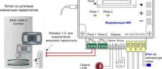
Automation of thermal curtains
Automation of thermal curtains is designed to improve the quality of climate solutions in the area of openings, simplify the processes of managing air curtains and reduce the cost of maintaining premises with installed curtains. An automatic heat curtain, with the right choice and proper adjustment of the automation, will always provide greater comfort for less money. At the same time, automation in the simplest cases can consist only of a limit switch for opening a door or gate and a remote control with a thermostat. Figure 2. Limit switch Figure 3. Remote control with an electronic thermostat These figures show the elements of the simplest circuit for allowing the air curtain to operate in automatic mode. The most advanced automation solutions allow for minimal human involvement in the daily process of controlling air curtains, and they can collect cost statistics automatically. The customer’s task is to select the optimal automation functionality taking into account the tasks facing him.
Equipment selection
It is better to choose brass ball valves for piping the heater - they last longer.
The elements that make up the system do not differ depending on the chosen circuit. To select the right components, you need to use the following recommendations:
- All fittings must comply with technical specifications. They are calculated based on the maximum temperature and pressure.
- The diameter of the elements must correspond to the size of the heating system pipelines.
Ball valves made of steel or brass should be selected as shut-off valves. For pipes with a diameter over 50 mm, flanged valves are required.
To simplify the work, buy taps with union nuts. To limit the flow, check valves are selected and placed on the return line or bypass of the units.
To control temperature and pressure, pressure gauges and thermometers are purchased. The temperature sensor is placed on the supply and return lines in front of the heater. The pressure gauge is installed in the pump group.
To create optimal coolant movement, install a circulation pump. It is mounted on an adjustable section, where it helps overcome hydraulic resistance. Additional parts include filters, valves, valves.
Attaching the thermal curtain
As a rule, air curtains are mounted on standard brackets, which are included in the air curtain delivery package. Additionally, many manufacturers offer installation kits for non-standard installations, for example, kits for attaching air curtains to the ceiling with studs. In some cases, when standard mounting kits do not meet the conditions for installing air curtains, the customer can order a non-standard kit from the manufacturer, for example, extended length studs or special extended brackets.
Installation recommendations
Floor installation of a water heater
It is not difficult to master the technique of installing supply air heaters. You will need to carefully study the assembly instructions and then strictly follow their instructions. Before starting work, it is taken into account that household models, even of relatively light weight, are hung on a base, the strength of which is checked in advance. Strong concrete or brick walls are suitable for this; Moreover, wooden and plasterboard partitions are immediately discarded. Next, the need to use a freeze protection thermostat for the supply ventilation channels is determined. If in this place the temperature can drop below normal, the installation of a thermal stabilizer is considered mandatory.
The procedure for carrying out installation work:
- A metal frame in the form of a bracket with holes for attaching the housing (mounting console) is installed at the selected location.
- The heater body is suspended, to which pipes with a set of shut-off valves are then connected in the sequence specified in the instructions.
- The mixing unit is also installed here if it was not installed before the installation work began.
They mount heaters on concrete walls under decorative panels.
There are two ways to cut into the heating system. In the first case, connecting fittings or couplings with gaskets are used, and in the second approach, welding is used. The latter option is more reliable, but its use is unacceptable in the presence of flexible connections.
One of the weak points of the mounted structure is the heat exchange pipes, which are subject to constant deformation. Replacing rigid steel tubes with flexible hoses will help increase the reliability of the system in the area where they are located. This technique will lead to a reduction in the load on the pipes, which at the joints are additionally sealed using a sealed compound.
If the heater body is fixed to a fixed and durable base, connection via rigid pipes is allowed. If during operation the device is expected to be moved or moved from the workplace, it is necessary to use a flexible connection. At the final stage of installation, the device is checked for functionality.
Immediately before testing, you will need to remove exhaust air from the exhaust channels, as well as check the condition of the valves and blind guides.