Warm water floors must heat with the correct uniformity, that is, the water in the circuits must be distributed according to the needs of each room. Such an effective heat consumption in the pipes of a liquid floor heating collector will allow you to save money and at the same time achieve the required level of temperature increase for the parameters of a particular room. It is the flow meter (also known as rotameter, water meter) that regulates the described aspects of the functioning of liquid-heated floors, and also provides all control, monitoring and regulation of water flow. We will describe the principle of operation of the device, its design, how to perform balancing and adjustment.
Ways to balance heated floors
For multi-circuit underfloor heating, setting the balance of the segments is a mandatory procedure for normal operation.
There can be many contours (branches), not only one for a separate room, but also several for different segments of large rooms.
In the first photo below, the system combines flow meters with control elements of different sizes (with adjusting rings and valves):
Balancing the circuits of water underfloor heating is carried out in the following ways:
- Install coils with approximately the same length, laying loops. They start from the minimum length of the main line for the smallest room and for other, larger rooms, install two or three circuits, each similar to its parameters.
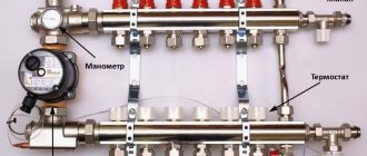
- The most effective method, ensuring simplicity and maximum accuracy, is a balancing group (measures, adjusts the flow intensity, its speed). Components:
- flow meter for underfloor heating (also known as water meter, rotameter, rotameter) with a valve assembly, integrated or separate. Such regulators are installed on each tube segment, so there is usually more than one;
- auto-cost stabilizer with variable gap;
- pair-type differential pressure regulator (inlet, return);
- valve with Venturi device.
It is the method of setting the balance of circuits with flow meters that is preferable, even when the first item on the list is maximally fulfilled. The balancing group can also consist of only water meters.
The importance of a flow meter in the design of a water floor
A warm water floor is a closed system with its own heating source, most often with gas or electric boilers, less often with solid and liquid fuels. The user pays for the energy, so savings are important in all cases, and most importantly for the first two units we mentioned.
If the circuits in all rooms have the same consumption, regardless of their parameters, then resource overuse will occur and an uncomfortable level of heating will be created, since each room has its own needs.
For the reasons described above, water heating floors are equipped with a balancing unit - a manifold (where the return flow is mixed) with a comb with water meters that simplify the adjustment of operation, that is, the level of flow intensity for the coils.
Efficiency depends on proper planning of resource costs. A flow meter is a unit that corrects the operation of a floor heated by a heated liquid; for multi-circuit structures it is almost mandatory and is assumed by default. The system can function without the component in question on the underfloor heating manifold. You can balance it manually, but such a procedure will be extremely complicated, time-consuming, effort-consuming, and the result will not always be as accurate as expected.
Tasks of water floor heating rotameters
The purposes of water floor heating flow meters are as follows:
- precise adjustment of the heated floor: flow rate, flow rate of the coolant, and, accordingly, t°;
- facilitating, simplifying the balancing process;
- visualization of settings levels;
- achieve the temperature/flow balance desired by the user;
The flow meter is an affordable, standard, and in most cases the default configurable element of underfloor heating. The water meter together with the mixing unit is actually the control unit for the entire equipment.
Equipment and capabilities
Products are manufactured under the Valtec brand by an Italian company. They have been on the Russian market since 2003, so they know our realities first-hand. We produce a wide range of plumbing engineering fixtures and devices. And collectors for heated floors are among them.
general description
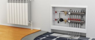
The Valtec underfloor heating manifold is made of brass or stainless steel. Or rather, most often, the body is made of stainless steel, and the “filling” is made of brass. In the catalog they are called a manifold block, since there are a couple of devices - for the supply and for the return pipeline. Complete kits are equipped with:
- there are flow meters on the feed comb;
- on the return pipeline there are manual shut-off valves.
Below is the supply and there are flow meters. At the top is the return pipeline, manual valves are installed
In this option, using flow meters, you can adjust the coolant flow in each of the loops, and manual valves on the return pipeline serve to block circulation. But this configuration can be automated. To do this, servo drives are installed on manual valves, which are connected to thermostats installed in the premises. In this way, a constant floor or air temperature can be maintained. Depends on where the heat sensors are installed, because the thermostat reacts to their readings.
An automatic air bleeder is also installed on the Valtec manifold. This is a device that allows you to remove air trapped in the coolant automatically.
Range
All collector blocks for Valtek underfloor heating can be divided into two groups: with and without adjusting flow meters. There are only three options in the first group and two in the second, but in each the number of connected taps is from two to twelve.
- With flow meters on supply
- VTc.594.EMNX. Body - stainless steel AISI 304, fittings - brass CW617N, seals - EPDM 70Sh, number of outlets - from 2 to 12. Operating pressure 8 bar, nominal diameter of manifolds - 1 inch, outlets - 3/4″ external thread, connection - eurocone. Price - from 9 thousand rubles. (for 2 outputs), up to 25 thousand (for 12 outputs).
- VTc.589.EMNX. Manifold for propylene glycol systems. Body - AISI 304 stainless steel, brass fittings and EPDM 70Sh rubber seals. Working pressure 9 Bar, coolant temperature not higher than 90°C. The nominal diameter of the collectors is one inch, the outlets are 3/4 inch with a Eurocone.
Compatibility table for various Valtec manifolds with components
- VTc.596.EMNX. Valtec brass manifold (CW617N brass) with nickel plated. EPDM 70Sh seals, fittings made of the same brass. Working pressure 10 Bar, outlet connection - Eurocone, diameter 3/4″.
- nominal collector diameter 1 inch, number of outlets from 3 to 12. Price from 12 thousand rubles. for 3 exits, up to 38 thousand rubles. for 12 exits;
- nominal collector diameter 1 and 1/4 inches, number of outlets from 4 to 12. Price from 9 thousand rubles. for 4 exits, up to 45 thousand rubles. for 12 exits.
- With manual valves
- VTc.588.EMNX. Stainless steel underfloor heating manifold VTc.588.EMNX with thermostatic valves. Coolant - water or propylene glycol, operating pressure 9 Bar, temperature 90°C. There are manual adjustment valves on the supply side. The number of outputs is from 3 (6 thousand rubles) to 10 (15 thousand rubles), connection via a 3/4″ eurocone, nominal collector cross-section is 1″.
- VTc.594.EMNX. Valtec brass manifold for systems with elevated temperatures - up to 120°C, pressure 10 Bar. Includes manual balancing valves and thermostatic ones.
- nominal diameter of the collectors is 1″, the number of outlets is from 3 (10 thousand rubles) to 12 (27 thousand rubles);
- collectors with a cross section of 1 and 1/4″, the number of outlets from 4 (16 thousand rubles) to 12 (36 thousand rubles).
The basic package includes manifold plugs, automatic air vents, drain valves (for filling or draining coolant), and brackets for installation.
Manifold and flow meter, equipment elements
A rotameter is a measuring device that shows the coolant consumption, how much of it passes through the connection point per unit of time.
A warm floor with a liquid system consists of the following components:
- circuit - tubes (loops, coils) through which warm water moves. It is not necessary, but it is desirable that the length of the coils and the methods of their installation be identical, which will simplify balancing;
- supply valves. This refers to the main taps that can completely shut off the flow from the source;
- pump. Hot water circulates thanks to it;
- a collector, or rather, a collector group with a flow meter. This part is the control unit, responsible for distributing the coolant along the circuits. It also has thermostats with valves and pressure gauges.
As you can see, the rotameter is installed precisely on the collector, and this is logical, taking into account the scheme we described above, since there mixing of water from the boiler and return occurs and its distribution occurs.
Temperature diagram example:
Solving the problem with underfloor heating contours
By connecting underfloor heating circuits to one manifold group, you can balance them in two ways:
- The first method involves creating even rings, but you can put several of them in one room, for example, you can put one heating ring in the bathroom, three in the guest room, and two in the kitchen. Likewise, the heating of all rings will be the same.
- If you do not want to create several rings in one residential area, then there is also a solution for you. Heating circuits can be of different lengths, but they should be connected through a specialized device - a flow meter
for heated floors.
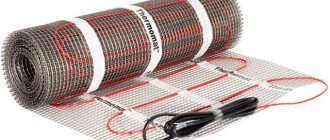
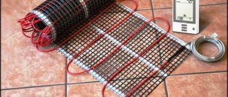
A flow meter
or rotameter is a combination of balancing valves that limit the amount of coolant released into the system. You can see an example of a rotameter in the photo.
Disadvantages of heated floors without a rotameter
The flow meter for the underfloor heating manifold regulates t° indirectly - through normalizing the fluid flows on the coils. Depending on the dimensions of the branch, a different amount of coolant is required, which cools down during movement precisely according to calculations.
If one small room is heated, then setting up the flow meters and they themselves may not be required. You can do without the device, and adjustments can be made by simply closing the supply tap or adjusting the pump. But if there is an object with several circuits, such manual adjustment will be extremely inconvenient; it will not be able to ensure that the values are set separately for each coil; in addition, it will be impossible to track consumption. With a water meter, balancing can be done by simply turning its adjusting nut, and the consumption level will immediately be visible on the transparent bulb.
Disadvantages if the underfloor heating collector does not have a rotameter:
- the temperature in rooms of different geometry, degree of thermal insulation, and length of contours will not meet their needs. For example, heating will be intense even where it is not needed;
- excess energy consumption will occur. The equipment will need to be used for a longer period, since uneven heating will lead to incorrect, and in certain areas, slower heat distribution.
It is a mistake to assume that optimal flow for several circuits can be achieved by adjusting the performance of the circulation pump and not equipping the floor with flow meters, since it is difficult to accurately calculate the length of the tubes. Such a calculation will lead to the fact that the amount of resource on the coils will differ from the calculated indicator. And also this violates the principle of choosing equipment: it is necessary to start from the needs of the user, and not from the parameters of the device.
VALTEC combined heating diagram
We present to your attention an example of a modern energy-efficient heating system based on VALTEC equipment. It is designed for a country house or any other facility with an autonomous heat source (boiler, etc.). The scheme provides for the combined use of traditional radiators and underfloor heating. This combination of technologies, as well as the applied automation, makes it possible to provide a high level of comfort at optimal costs for the purchase of equipment and its operation. The diagram uses and displays components from the current VALTEC range.
| № | vendor code | Name | Manufacturer |
| 1 | VT.COMBI.S | Pumping and mixing unit | VALTEC |
| 2 | VTC.596EMNX | Manifold block with flow meters | VALTEC |
| 3 | VTC.586EMNX | Stainless steel manifold block become | VALTEC |
| 4 | VT.K200.M | Weather-compensated controller | VALTEC |
| 4a | VT.K200.M | Outdoor temperature sensor | VALTEC |
| 5 | VT.TE3040 | Electrothermal servo drive | VALTEC |
| 6 | VT.TE3061 | Analog servo | VALTEC |
| 7 | VT.AC709 | Electronic room chronothermostat with floor temperature sensor | VALTEC |
| 8a | VT.AC601 | Room thermostat | VALTEC |
| 8 | VT.AC602 | Room thermostat with heated floor temperature sensor | VALTEC |
| 9 | VT.0667T | Bypass with bypass valve to ensure circulation when loops are closed | VALTEC |
| 10 | VT.MR03 | Three-way mixing valve to maintain return temperature | VALTEC |
| 11 | VT.5012 | Thermal head with remote sensor | VALTEC |
| 12 | VT.460 | Security group | VALTEC |
| 13 | VT.538 | Squeegee | VALTEC |
| 14 | VT.0606 | Dual manifold nipple | VALTEC |
| 15 | VT.ZC6 | Communicator | VALTEC |
| 16 | VT.VRS | Circulation pump | VALTEC |
Explanations for the diagram:
The use of the VALTEC COMBIMIX pump and mixing unit allows you to link high-temperature circuits (heat source and radiator heating) and underfloor heating circuits with a low coolant temperature into a single system.
The distribution of coolant flows is organized using collector blocks VALTEC VTc 594 (radiator heating) and VTc 596 (warm floor).
The wiring of the high-temperature heating system and the heating circuits are made of VALTEC metal-plastic pipes. The pipelines were installed using press fittings of the VTm 200 series; connection to manifolds – with crimp manifold fittings for metal-plastic pipe VT 4420.
Regulation of the underfloor heating is organized using the VALTEC K100 controller with weather compensation function. Thanks to this, the water temperature in the heated floor circuits changes depending on the outside air temperature, which guarantees savings in energy resources used for heating. The control signal from the controller is sent to the analog electrothermal servo drive of the control valve of the COMBIMIX unit.
Thermal comfort in rooms with underfloor heating is maintained by a room thermostat VT AC 602 and a chronothermostat VT AC 709, equipped with air and floor surface temperature sensors. Through electrothermal actuators, these automation modules control the valves on the return manifold of the VTc 596 block.
A thermostat with a remote temperature sensor VT AC 6161 was used as a safety thermostat. It stops the circulation pump of the COMBIMIX unit if the specified maximum temperature of the coolant in the supply to the heated floor circuits is exceeded.
The heat output of the radiators is regulated by the room thermostat VT AC 601, which controls the valves of the VTc 594 manifold block using electrothermal actuators.
The heat source circuit is equipped with a boiler safety group, a membrane expansion tank, and VALTEC check and drain valves.
Ball valves of the VALTEC BASE series were used as shut-off valves.
Water meter design
The design of the rotameter is mechanical, the material is plastic and/or metal (brass). The upper segment of measuring and adjustment models has a transparent tube with graduation.
There is a float inside, which is why the device is called “float”. This element, fixed to the rod, is supported by a spring (the flow changes the pressure, compresses/decompresses it). At the bottom inside there is a valve connected to the described elements, which changes the flow of liquid according to their position.
Rules for refueling the system
It is impossible to correctly configure the functioning of a water structure if the volume of liquid in the pipeline changes independently. This can happen if there is air in the system - see the instructions on how to bleed air from a heated floor yourself
Therefore, it is important to both professionally install the structure and fill it correctly.
To ensure high-quality filling of the system, both collector branches should be equipped with automatic air vents. Refilling of floor hinges should be carried out separately from other heating devices. The generator and radiators are filled in advance. Before refueling, the manifold inlet valves are closed.
To properly start the floor, you need to connect a hose from a water supply source or pump to the supply valve, and a hose for air outlet to the return valve.
You need to start filling the water floor from the collector and its distribution units. To do this, the flow meters of the supply valve are opened fully, at which point the return taps should be turned off.
The loops are filled one by one, water is released until it comes out of the bleed hose clean and without air bubbles. The water should be started with low pressure, this will make the process of air leaving the pipes more even. After threading all the loops, the device can be turned on.
Working with Manifold Flow Meters
Balancing a warm floor means determining the standards for each loop. After all, depending on the size of the floor branch, in order for the coolant to cool down according to the calculated value while passing through it, the amount of water required varies. The volume of liquid that the loop passes through is the thermal load on it.
It is often recommended to determine the coolant flow rate based on the power of the pump, that is, the volume of incoming liquid is divided proportionally by the length of the loops. However, you should abandon this method, since it is not easy to accurately calculate the size of each coil using this method.
In addition, calculations using this method lead to a discrepancy between the pressure in the loop and the calculated value, which makes it impossible to adjust the design.
The adjustment process itself with flow meters is simple - an article with step-by-step instructions. The throughput of the device is adjusted depending on the model, either by turning the body or the stem using a key. The device displays the amount of water in liters that has passed per minute; you just need to set the desired value.
Basically, when adjusting the capacity of one loop, a change occurs in the others. Therefore, the process should be repeated sequentially with each flowmeter. Significant failures indicate that the fittings have poor flow capacity, or the circulating pump has low performance.
Kinds
The design of different models of combined type measuring and adjusting float water meters is almost the same:
Types of water meters based on functionality for underfloor heating manifolds:
- measuring - a shut-off valve must be installed to it, the valve of which is turned by the user to adjust it, depending on the values shown by the water meter;
- regulating - only for coolant distribution;
- combined - two types are combined, with a built-in valve. Some models can perform automatic adjustment.
For underfloor heating, the first and second types of float rotameters are most often used.
Adjustment based on return water temperature
Coolant flow, power and temperature difference between the supply and return pipelines are interconnected. If you reduce the coolant flow in the loop, the temperature difference will inevitably increase. It is by this dependence that the correct setting can be determined.
In the event that all underfloor heating loops have the same temperature difference between the supply and return pipelines, this will mean that in all loops the coolant flow corresponds to the current power. And since the temperature in the supply manifold is the same for all loops, it is possible to equalize the temperatures only in front of the return manifold.
It is more convenient to take temperature readings using special thermometers that are mounted between the pipe and the return manifold.
The reference temperature is measured on the longest loop. After this, all other valves are adjusted depending on deviations from this temperature. If the temperature on some loop is lower than the reference one, then the flow rate in this loop is also low. Therefore, the valve of this loop must be opened slightly. If the coolant flow is higher than the reference value, the valve must be closed. After adjustment, you must wait half an hour and then repeat the operation. And repeat this until the coolant temperature in all loops in front of the return manifold is equal.
How does the water meter of a heating floor collector work?
Let's describe how the flow meter works. The functionality of the device is ensured by its valve part; it is equipped with control rings or a valve. When these controls are moved, the lumen of the pipe narrows, accordingly, the flow weakens/increases, the temperature on the circuit changes, and at the same time the float inside the transparent flask moves, showing the set value. In this way, the thermal power of coils with different hydrodynamic resistance is balanced. There are models with a valve installed separately; the operating principle is similar, the elements are simply separated.
So, in a float rotameter, namely such devices are used for floor water heating systems, there is a plastic transparent flask with a float indicator indicating the intensity of circulation. The liquid constantly flows inside, drowns the specified element (it can be called “eternally floating”), which the spring tries to return to its place; the more powerful the flow, the more it sinks.
Ideal design of the collector group
The best system is considered to be this collector group, in which the supply manifold is equipped with a rotameter, and a thermostat is installed on the return manifold. Such a system will make it possible to direct a sufficient amount of coolant to each circuit, and the return collector of such a system will close and open the circuits as the water cools.
It is also necessary to say that the system can be improved with an automated Mayevsky tap, which is placed on the supply manifold; for its part, it must be connected to a circular pump with a bypass valve.
It will work like this:
- Mayevsky taps will remove air from the system, which interferes with its good operation;
- If it gets warmer outside, the external water thermostats will close the circuits, and the bypass valve will reduce the increased pressure from inside the system.
If we talk about how a heated floor
, you need to make a correction: there are three types of rotameters:
- The measuring rotameter is installed simultaneously with the valve, which is changed manually, depending on the measured readings;
- The calibrating rotameter controls the amount of incoming coolant;
- The 3rd type combines the previous two, but it also has a very high cost.
Rotameter installation
Let's consider how to correctly install the most commonly used type of water meter - combined with a valve integrated into it. The device is placed strictly vertically: it is simply screwed into the seat, onto the manifold comb on the supply or return. The option is prescribed in the technical documentation and depends on the direction of the liquid inside. The manifold already has sockets for the threads of rotameters as standard, and is often sold already assembled or as a set with them.
Additional sealing materials are not required, but if a leak occurs, they can be used. The standard product has a union locking nut and a polypropylene ring seal.
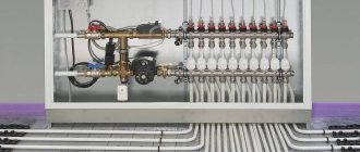
The traditional appearance of the unit diagram is as follows: water meters with valves on the supply segment, thermostats on the return segment (it can be the other way around).
On the comb of multi-circuit equipment collectors there are seats for each segment, that is, a larger number of water meters are used for each coil that needs to be configured. The device is fixed with a union nut; there may be other mounting options.
If thermostats are installed on the pumping and mixing part, then an additional adjustment to the water meters is also carried out: when the water reaches a certain t°, a valve is activated on the collector return, changing the gap for the flow of water.
The scale of the rotameter flask shows the flow; it is filled with water, the level of which varies depending on the intensity of consumption. There is also a float, which stops opposite the corresponding division. The water meter will immediately show the value, and balancing will be done with a few simple movements.
It is possible to adjust the warm floor contour correctly only if the liquid level in a transparent measuring container with a scale is strictly horizontal. Particular care must be taken to ensure that the device itself is installed exactly vertically. To do this, install the manifold with seats exactly, checking with a plumb line, bubble, and level. However, if the position of the node has deviations, then the system will work normally, but during adjustment it will be necessary to take into account errors.
Step-by-step instructions for installation and adjustment
The rotameter is installed strictly vertically. To ensure that the liquid level in the flask is accurate, the collector itself is also mounted according to the level. If the comb pipe is installed crookedly, the temperature adjustment will be incorrect.
Since finishing work often occurs after installation of the collector, it is necessary to protect the assembly and its components from possible damage. The best option is to make a niche or a special cabinet for it in the wall.
Installation and adjustment:
- Using a wrench, screw the flow meter into the process inlet of the return line of the manifold;
- Turn the membrane (flask) counterclockwise to open the pressure meter;
- Remove the factory protective ring;
- Turn the brass housing ring clockwise to the desired pressure level. This is balancing the energy flow rate. The float on the scale will indicate the set value;
- Cover the brass ring with a cover plate. This must be done to avoid damage to the device, especially if the water heated floor unit is not closed in a niche or cabinet;
- Check the system operation.
During operation of the unit, the flask remains open so that the level of the water float is visible. If balancing is needed during operation, the membrane is simply turned in the desired direction.
Adjusting the rotameter in stages
It is appropriate to call the procedure balancing a heated floor, since the boiler has limited capabilities and the goal is to create the most effective balance in the distribution of its resource between the heating circuits.
The idea is simple: each rotameter shuts off the flow of water according to the principle of a regular tap; the lower the flow it creates, blocking the liquid inlet to the circuit with its valve, the lower the temperature, and vice versa. The essence of the adjustment is elementary - limiting the pressure and volume of incoming coolant.
Adjustment of heated floor flow meters, the procedure for installing them on the heated water floor manifold is almost always prescribed in the product instructions.
Let's look at installation and how to adjust (balance) for a common standard size float flow meter with two washers-rings for adjustment at the bottom of the body:
- Insert the rotameter into the seat on the manifold comb.
- Remove the protective sleeve and safety pin or similar device, usually in the form of a ring. Different models almost always have the first one, but may not have the second one;
- Screw in the product, tightening it with a wrench with a small reasonable amount of force. This procedure can also be performed without a tool, by hand, since it does not require particularly strong tightening, the main thing is that the device sits tightly in the socket. There are also sizes with a locking union nut;
- Turn counterclockwise. the upper adjustment ring, the valve will open completely. With this manipulation, the device is brought into readiness, into its original state. The flow indicator will move to o.
- Start the system.
- Next, the same upper ring is used to set the desired value, determined according to the user’s calculations.
- To ensure that the set parameter does not go astray, fix it by turning the bottom washer until it stops.
- Upon completion of the procedure, do not forget to cover the adjustment unit with the same protective sleeve. This will prevent mechanical damage and shifts from accidental influences.
- The last stage is to check how the configured equipment is heated, to observe for some time the intensity and speed of reaching the desired temperature.
It is necessary to adjust it smoothly, since reducing the flow on one device increases its intensity on other circuits. The adjustment, that is, the set pressure, will be indicated by the pointer position opposite the scale gradations.
For models of rotameters without an integrated valve with a segment with a speed scale, such a valve must be installed separately. When balancing a heated floor with flow meters of this type, these valves are switched to a fully open state, and then the system is started and adjustment is performed by adjusting them. That is, at its core the process is similar to the one described.
Should I assemble a collector or buy a ready-made one?
Collectors can be prefabricated, ready-welded or homemade. Let's consider their advantages and disadvantages.
Ready welded
They are usually produced in the form of supply and return combs welded together with a specified number of pipes.
Advantages
- Fast installation - no need to assemble fasteners.
- Minimum qualification requirements for an installer
Flaws
- Difficult to configure for a specific system.
- The number of pipes may not meet the needs, in which case they will have to be blocked off with plugs and not used.
- The collector can be equipped with elements that are unnecessary for a particular heating system. For example, it may have a hydraulic distributor (hydraulic arrow), which is only useful in networks with a large number of pumps.
- The return and feed combs may be welded together, making it difficult to attach separate loops to them. The pipes on factory mixers are usually located at the same distance from each other, but this is not always convenient.
Homemade
You can make a collector with your own hands from available materials: steel pipes with a round or square cross-section. To do this, holes are cut in them and pipes are welded. Couplings are made from round sections of smaller diameter.
Advantages
- Making a collector with your own hands is profitable from a financial point of view.
- You can make a drawing and manufacture an individual manifold for a specific system.
Flaws
- To perform this job, you will need skills in working with a welding machine.
- It will take more time.
- The non-separable design makes it difficult to repair and replace individual elements.
Prefabricated
Such distribution units are assembled from factory parts, which are purchased separately or as a kit. They will be discussed further.
Advantages
- There is variability when designing a collector unit for a specific heating system.
- Does not require special skills or equipment for installation.
- Possibility of separate dismantling of feed and return combs.
- High installation speed.
Flaws
- Components from different manufacturers may not fit together.
- This option usually costs more.
Features of manifold flow meters
Characteristics of the technical aspects of rotameters for heated floors:
- operate completely autonomously and do not require any power sources;
- make it possible to use the coolant in maximum volumes at the lowest possible flow rate. Thus, in a room, apartment, house, the energy consumption of other heaters and other heating is further reduced. It also frees up additional resources that can be used for other purposes;
- devices capable of providing complete control over the amount of coolant entering the floor heating circuit tubes;
- installation is extremely simple: the product is screwed into an existing seat in the manifold. The same basic balancing: valve, adjusting rings. In this case, the set levels are visible on the scale;
- does not require special maintenance. Once the piston position is set, it remains until the user changes it.
An important feature is that the flow meter is installed together with the collector - these two units are interconnected, it is they that control, effectively and simply adjust, and balance the heated water floor.
Collector heating system. Principles of its work.
How to install a mixing unit for a heated floor with your own hands
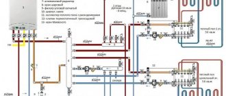
As I said earlier, this type of heating system is most often used in two or more storey buildings. But no one will forbid you to use it in a one-story house. It all depends on expediency. In addition to heating devices, an indirect heating boiler or a heating system for a swimming pool or greenhouse can be connected to the collector. So in a one-story house you can use this kind of trick. The main thing is not to forget that in a collector heating system there can only be forced circulation of the coolant. This means that it must have at least one, and most often several, circulation pumps. Look at the picture below:
The figure shows a diagram without an indirect heating boiler. This is done here because a double-circuit gas boiler is used. Well, if the boiler is single-circuit, then everything will look a little different:
It has everything modern homeowners love:
- Radiators.
- Water heated floors.
- Backup electric boiler.
- Indirect heating boiler.
If you don’t count them together with the boiler pump, then there will be 5 of them. To ensure that the circulation pumps do not create a pressure difference between the “supply” manifold and the “return” manifold, a hydraulic arrow is used here. Thanks to it, the boiler circulation pump can always provide the required coolant flow through the boiler heat exchanger, which has a positive effect on its service life. The underfloor heating circuits are connected through their collectors with autonomous circulation groups. Here you need to take into account the possibility of an emergency power outage. To ensure the operation of the “brain” of the boiler and circulation pumps during a shutdown, you will need. Without it, the circulation of coolant in the system will stop, and this is fraught with all sorts of unpleasant consequences.
The main advantage of this heating scheme is the ability to turn off individual branches without stopping the entire system. This feature is very helpful in case of emergency repairs. Well, the downside will probably be the price of all this pleasure. Although, if you are doing it for yourself and for a long time, then it makes sense to do everything wisely. Otherwise, your stinginess will make you pay twice! On this optimistic note, I will end this post, I look forward to your questions and likes on social networks!
Calculation
Calculating what heating temperature is required to heat a particular room can only be done experimentally, that is, the user must try several settings, analyzing the time to achieve a comfortable environment in the room and the temperature level there. Fortunately, this is much easier to do with a rotameter than fiddling with the supply valves and pump manually.
There are no fixed values for rooms; this nuance is due to the fact that many factors influence heat retention in a room: thermal insulation, area, length of the coil, and the like.
On combined models, you can make a preset (usually this is done) by the number of valve revolutions - each full turn reduces/increases the clearance by a fixed value. You can use the following method:
- First, the volume of coolant required for each circuit is calculated, its percentage relative to the total amount of liquid for the entire system.
- Based on the result obtained, the initial position of the valve (ring) is set for each section.
- The final adjustment of the flow meter is made during the operation of the system, based on the actual established temperature, according to feelings of comfort.
As we have already noted, for one or two rooms or rooms with identical parameters, a collector group with flow meters is desirable, but not as significant as for houses and apartments where several zones of different sizes are heated.
With equal coolant flow for the circuits of a large and small room, achieving the desired temperature in them will be different. The larger the area, the lower the quality of thermal insulation, the lower the level of heating will be. Accordingly, larger rooms will require a more intense and significant flow. And, conversely, in a smaller object you need to set the flow rate lower, otherwise it will be hot. But there is also a nuance here: if it has poor thermal insulation, then the values may become equal.
As you can see, the calculation is influenced by many factors; the comfortable mode even depends on the time of year. Adjustment is also called balancing, since the limited resource from the boiler is distributed; a change on one coil affects the others. Tuning can be done frequently, so the simplicity provided by flowmeters is highly sought after.
Let's give an example. Inside the house, an underfloor water heating system is installed for the bathroom and another room, for example, for the living room. Without a rotameter, a gas boiler will heat the liquid for the specified rooms equally, and one temperature regime will be established. It may be comfortable for the living room, but it will be hot in the bathroom.
For heating the first one requires more heated water from the boiler, for a small bathroom less. A water meter will allow you to quickly and comfortably bring the temperature of each room to the same level or set it to a different, but comfortable level, taking into account the characteristics of the room.
Also, when balancing, it is important to pay attention to the length of the circuit tubes, regardless of its configuration.
Let us note some more advantages of flow meters; the device will allow:
- it is easy to control the volume of liquid of a certain temperature sent for heating, which also entails the opportunity to more rationally manage the energy source (boilers). If it is of an electric type, then this nuance is very relevant;
- warm all branches evenly, avoid temperature fluctuations, which will increase comfort. On the other hand, it will allow you to turn off the heating where it is not needed, or reduce/increase it as desired by the user;
- You can visually monitor the volume of coolant flowing from the boiler through the main pipes. By looking at the flow meters, their bulbs with graduations and indicators, you can immediately determine visually the heating level of the room (you will also need to compare its dimensions and other parameters) and how much resource is being consumed.
Manual adjustment of coolant temperature
How you adjust the temperature will depend entirely on the equipment you are using. For example, if a system with a temperature controller and a servo drive is installed, then the setup is carried out according to the instructions from the manufacturer of this device. In this case, the adjustment is performed automatically. Now let's look at the manual method of setting the temperature using thermal heads.
Thermal heads can be installed both on the supply and return side of the coolant.
First of all, the system up to the heated floor must be completely filled with coolant and freed from air.
But it is important not to rush here, otherwise air jams may form. If the connection was made from the boiler, then before starting water into the heating circuits, turn off all taps
Afterwards, open the supply/return loop on one loop, filling it with coolant. The air should come out of it through the air vent. Now turn on the circulation pump so that the coolant begins to move in this loop. At the same time, turn the temperature on the boiler to 35°. To the touch you should feel that hot water is flowing in the return and supply in the heating circuit. If everything works properly, close this loop and open a new one. Using this method, you pump and check each loop of the heating circuit. When you have configured each circuit, you open all the taps and adjust the required temperature by touch. In some loops the faucet will need to be opened completely, while in others it is enough to open it slightly.
The coolant temperature in each circuit may be different. There are several reasons for this, such as the length of the loop. The shorter the circuit, the faster it warms up and vice versa.
Thus, manual temperature adjustment is carried out. It is enough to do it once a year. But here it is important to take into account the nuance. The underfloor heating system is inertial. What does this mean in practice? If you make changes to one of the hinges, you will have to wait several hours to notice a noticeable change in the temperature inside the room.
If you installed flow meters on the collector, the difference between the readings can reach up to 0.5 liters.
How to choose
A manifold for underfloor heating is often sold ready for assembly; the kit may not include rotameters, but usually recommended flow meters are always specified in the technical documentation for each version of such a product.
Some tips on how to choose the right rotameter:
- The more elements of the device are made of metal (brass), the better. This product is more wear-resistant. But also, if you need to save money, plastic products are often used: the environment of use does not create too much stress, so a device with a plastic stand will work for a long time;
- When purchasing, it is important to inspect the product to ensure its integrity (especially the flask);
- the spring inside must be steel. The material is indicated in the instructions; if this item is not present, it is likely that the manufacturer produces unreliable products;
- polycarbonate bulb of quality products;
- recommended minimum parameters (specified in the instructions): the product must be designed for +110° C and above, pressure - from 10 bar;
- throughput from 2–4 m³;
- Availability of a certificate, warranty - from 5 years.
Of course, if there are many circuits, it is advisable to buy a water meter for each, since a change in the flow on one branch changes it on all the others, this will allow for more rational use of the boiler’s capabilities. The comb will be a kind of control unit with protruding rotameters, with different positions of indicator floats inside the flasks.
Occurrence of a problem
First of all, it’s worth looking at a specific example of the occurrence of such a problem and its consequences:
- You install heated floor contours in the bathroom, living room and kitchen;
- They are connected to the same collector;
- The area of the bath, kitchen and living room is clearly different, therefore the length of the heated floor circuit will vary in each room, and accordingly the coolant (water) consumption will be different.
It’s worth saying what this will lead to. Short heating rings have less hydraulic resistance, so water circulates in them much faster than in long circuits, which creates a temperature difference in rooms at the same temperature of the coolant supplied from the collector.
An example of a solution to a problem, in which we will analyze the principle of correction, will be a simple wall-mounted radiator. If you connect radiators with different numbers of sections and pipe lengths to one collector, the problem described above will arise (read: “Heated floor collector diagram - how everything should work”).
The problem with radiators is easily solved, because the instructions say that by installing a thermostat on each battery, you can control the quantitative flow. Typically, a thermostat is an ordinary valve. The problem is solved in a similar way with a heated floor system.
Ways to regulate
Depending on what equipment is used in the heating system, it is possible to control the temperature of the assembled heated floor in several ways. In this article we will tell you about four:
- manual adjustment;
- group regulation;
- customization;
- integrated control mode.
How to adjust the temperature correctly?
Correct setting of a warm water floor is carried out according to the following indicators:
| Room | Optimal t,°C | Permissible t,°C |
| Living room | 20-28 | 18-24 |
| Kitchen | 19-21 | 18-26 |
| Corridor | 18-20 | 16-22 |
| Bathroom | 24-26 | 18-26 |
| Bathroom | 19-21 | 18-26 |
Important Indoor air humidity parameters: acceptable 60%, optimal 40-50%.
During the control process, you need to set up a device that controls water flow; it increases and decreases its supply at the right time.
Manual
With this adjustment, the entire process is done manually, and conclusions about the temperature are based on personal feelings. Naturally, with such measurements, inaccurate data is quite acceptable. Therefore, the technology for adjusting the water floor should be carried out according to this list:
- In the operation of heated water floors with laminate or parquet covering, thermal heads are used, which are mounted on both pipelines - supply and return. In manual mode, adjustments are made: the feed is increased or decreased.
- The floor temperature is adjusted only when each loop is filled with water; when filling, you need to ensure that there is no air.
- In the process of filling the pipelines with water, first of all, there must be water in the rest of the heating system. This is done by opening the taps that give access to the heat carrier to the entire system, as well as the return manifold valve. Only after this can you open the forward and return pipes of one loop and fill it completely, checking and preventing air from entering (release it into the air vent).
- The next step is to start the pump to move the water through the pipeline. Determine the heating with your hand, and when the pipes are warm to the touch, close the loop.
- The same is done with each loop.
- When all loops are filled, turn the valves to open. The water supply of each loop can be set by determining the temperature by hand.
- The temperature of the water in the pipes depends on their length, so it is advisable to install them of the same size.
Attention With this type of adjustment, all its stages must be carried out with a two-hour break in order to understand the effectiveness of the actions.
Group
The group regulation process is convenient due to its accuracy of readings. It is based on an automatic increase or decrease in temperature, as well as an increase or decrease in the supply of coolant (water). This simple type of regulation uses constant circuits and climate control.
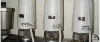
Valve with thermal head
In work performed according to the constant circuit, valves with thermal heads are used.
If it is necessary to change the temperature, the system expands or contracts the capillary tube that regulates the valve opening. This continues until the desired mode is set.
The adjustment occurs automatically. Depending on how many degrees Celsius the air in the room is, the system’s automation determines the temperature that needs to be obtained and commands the valve to close or open.
Comprehensive and individual control mode
Adjustment of floor temperature in individual mode occurs using sensors located in each room. Individual adjustment differs from group adjustment. In the first case, the climate is set separately for each room at will, and in the second, a general temperature regime operates for the entire system.
Useful There is a method that combines individual and group modes for adjusting a warm water floor. That’s what it’s called – complex. In this method, temperature correction is carried out both in the entire house and separately in each room.