To ensure comfortable living in the cold season, even at the stage of designing a private house, you need to take care of the calculation and installation of heating. Correctly performed thermal calculations will allow you to determine the optimal and cost-effective heating system. Any error can lead to you freezing or the building becoming hot and stuffy.
Independent calculations will not be a problem for people with technical education. However, not everyone has physical and mathematical skills, so an online calculator will be a good guide to calculations. It will help identify heat losses at home and calculate the power that the boiler should have. It will also determine the number of radiators needed and how many sections it should have. It will calculate heating costs for you, which will be useful for choosing a suitable heat source. Collect the necessary data for the calculation.
Determine heat losses. To do this, you need to know what material the external walls and floor coverings are made of, how they are insulated and their thickness. Measure the area of the house, windows and exterior doors. High intensity of heat loss from ventilation and sewerage. They also need to be taken into account in the calculations.
The climatic conditions of the location of the house play an important role in the choice of heating system. Find out the average annual and minimum temperatures in your area, as well as the average wind speed.
VALTEC.PRG.3.1.3. Program for thermal and hydraulic calculations
The VALTEC.PRG program is publicly available and makes it possible to calculate water radiator, floor and wall heating, determine the heat demand of premises, the required flow of cold and hot water, the volume of sewage, and obtain hydraulic calculations of the internal heating and water supply networks of the facility. In addition, the user has a conveniently arranged selection of reference materials at his disposal. Thanks to its clear interface, you can master the program even without having the qualifications of a design engineer. The program meets the requirements of Russian regulatory documents governing the design and installation of engineering systems (certificate of conformity).
- Difference between version 3.1.3 and version 3.1.2:
- added module for calculating pipe capacity;
- amendments have been made to the module for calculating water demand according to SNiP - it is possible to continue the calculation if the probability is more than one (insufficient number of devices);
- the “Pipes” reference table has been expanded;
- The User's Guide has been updated.
Training videos:
Calculation of heat loss of a cottage. Part 1 Calculation of heat loss in a cottage. Part 2 Calculation of underfloor heating Part 1 Calculation of underfloor heating Part 2
Calculation of heating costs
A good heating system requires quite a large financial investment. The main costs are related to:
- Heating system equipment. It includes a boiler, pump, radiators and wiring material.
- Installation of a heating system.
- Fuel costs. The amount of money you spend depends on the fuel you choose.
- Maintaining equipment in working order.
When calculating costs, the specific heat of combustion must be taken into account. Calculate by dividing the heat loss per season by the calorific value of the raw material to obtain the amount of fuel used. Multiply by cost per unit.
Another calculation method is kW consumption per hour. A house with an area of 120 m2 consumes 12 kW of heat energy. 8640 kW comes out per month. The method is suitable for gas and electricity users
Valtec “Sputnik” software package
The Valtec “Sputnik” software package is intended for use in the housing and communal services sector (management companies, homeowners' associations) and industry. The intuitive interface makes it easy for users to quickly learn. A number of special reports for management companies (homeowners associations, resource supply organizations) and integration with accounting programs (1C) make it easy to generate payment receipts. The control center includes reports that allow you to track emergency situations, unauthorized access to resources, and requests from subscribers from your personal account.
Integration into the Housing and Public Utilities GIS has been introduced to simplify reporting in organizations.
- Main features:
- Collection of readings from metering devices, event sensors, remote resource limitation
- Online emergency monitoring
- Data storage
- Generating special reports
- Integration with related software products used in the organization’s business processes (1C, video surveillance, POS, etc.)
- Open API
- Recommendations for saving resources
To familiarize yourself with the program's capabilities: Login: demo Password: demo
In the case of a comprehensive supply of metering devices and dispatch systems, a license file that allows you to fully work with the program is issued free of charge. The server is formed on the customer's side.
As an additional paid service, it is possible to use a Valtec remote cloud server.
For commissioning, commissioning of a facility or testing of dispatch system equipment, a free test license file valid for 1 month is provided.
For details on obtaining a test license, please contact the managers working in your region.
Types of circulation pumps
The design of a typical circulation pump consists of a housing made of stainless metal, a ceramic rotor and a shaft equipped with a wheel with blades. The rotor is driven by an electric motor. This design ensures that water is taken from one side of the device and pumped into pipelines from the outlet side. The movement of water through the system occurs due to centrifugal force. In this way, the resistance that arises in individual sections of the heating pipes is overcome.
All such devices are divided into two types - dry and wet. In the first case, there is no contact of the rotor with the pumped water. Its entire working surface is separated from the electric motor by special protective rings, carefully polished and adjusted to each other. The operation of dry-type pumps is considered more efficient, but during operation there is quite a lot of noise. In this regard, separate isolated rooms are equipped for their installation.
When choosing such models, you should take into account the presence of air turbulence generated during operation. Under their influence, dust rises into the air, which can easily get inside the device and break the tightness of the sealing rings. This will lead to failure of the entire system. Therefore, a thin film of water is present between the rings as protection. It provides lubrication, preventing premature wear of the rings.
Wet-type circulation pumps have a distinctive feature in the form of a rotor that is constantly located in the pumped liquid. The location of the electric motor is securely separated by a sealed metal cup. These devices are usually used in small heating systems. They make much less noise during operation and do not require additional maintenance measures. Typically, such pumps are periodically repaired and adjusted to the required parameters.
A significant disadvantage of these pumps is considered to be the low efficiency due to the insufficient tightness of the sleeve separating the stator and the coolant
When choosing the right model, you should pay attention to the fact that the pump has not only a wet rotor, but also a protected stator
The latest generations of circulation pumps are almost completely automated. Smart automation ensures timely switching of winding levels and significantly increases the productivity of the device. Such models are most often used when water flow is stable or slightly varying. Thanks to stepwise adjustment, it is possible to select the most optimal operating modes and significant energy savings.
VALTEC SET software package
VALTEC SET is a calculation and graphic program for the design of radiator and underfloor heating systems (CO module), as well as for the design of cold and hot water supply systems (H2O module) using VALTEC equipment. The program was developed by SANKOM Sp. z oo based on the latest version of the Audytor CO program – 7.2. The product allows you to design heating and water supply systems, and perform a full range of hydraulic and thermal calculations.
Get CO Basic module keys
Get H2O Basic module keys
Content
The calculation is done primarily to determine the resistance in the pipes of the heating system.
When calculating the hydraulic mode, you need to understand that the functioning of the old (centralized) heating control program and the modern (autonomous) one has a significant difference. And besides, the highest quality materials predominate in modern systems. The use of autonomous heating helps reduce energy consumption, that is, increase efficiency.
Many problems are caused by poor-quality installation of the frame itself, therefore, during installation and hydraulic calculations, it is necessary to seek the help of specialists with the necessary knowledge and experience.
Take care of insulating your garage. Read about insulation using a potbelly stove for a garage.
Broaden your horizons, find out how a heating and cooking stove is made from bricks
Do the right thing, find out how to install boilers in a private house: https://prootoplenie.com/otopitelnoe-oborudovanie/kotlu/chastnuy-dom.html
During installation and hydraulic calculations, take into account:
- hydraulic resistance;
- pipe diameter;
- pipeline type;
- silent operation of the system.
Accurate calculation is a costly undertaking, but the data is necessary for the further reliable operation of heating systems.
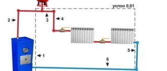
The circulation resistance calculation (measured in Pa) can be calculated for:
- heating system using a circulation pump (the required pump pressure is determined, and then the pipe diameter is determined);
- systems in which circulation occurs due to the difference in densities (naturally) of the supply and return pipelines (calculated: the permissible speed of water circulating in the pipes; hydraulic resistance; at the last stage - the diameter of the pipes).
Circulation pump
VALTEC CO 3.8. Heating system design software
VALTEC CO is a calculation and graphic program for designing radiator and underfloor heating systems using VALTEC equipment, developed by SANKOM Sp. z oo based on the latest version of the Audytor CO program – 3.8. The product allows you to design and regulate heating systems, and perform a full range of hydraulic and thermal calculations. The program is certified for compliance with the current construction standards of the Russian Federation and the requirements of the Voluntary Certification System of NP "ABOK" (
).
Determination of coolant flow and pipe diameters
First, each heating branch must be divided into sections, starting from the very end. The breakdown is done by water consumption, and it varies from radiator to radiator. This means that after each battery a new section begins, this is shown in the example presented above. We start from the 1st section and find the mass flow rate of the coolant in it, focusing on the power of the last heating device:
G = 860q/ ∆t, where:
- G – coolant flow, kg/h;
- q – thermal power of the radiator in the area, kW;
- Δt – temperature difference in the supply and return pipelines, usually 20 ºС.
For the first section, the coolant calculation looks like this:
860 x 2 / 20 = 86 kg/h.
The result obtained must be immediately plotted on the diagram, but for further calculations we will need it in other units - liters per second. To make a translation, you need to use the formula:
GV = G /3600ρ, where:
- GV – volumetric water flow, l/sec;
- ρ – density of water, at a temperature of 60 ºС is equal to 0.983 kg / liter.
These tables show the diameters of steel and plastic pipes depending on the flow rate and speed of the coolant. If you open page 31, then in Table 1 for steel pipes the first column shows the flow rate in l/sec. In order not to make a full calculation of pipes for the heating system of a private home, you just need to select the diameter according to the flow rate, as shown in the figure below:
So, for our example, the internal passage size should be 10 mm. But since such pipes are not used in heating, we can safely accept a DN15 (15 mm) pipeline. We put it on the diagram and move on to the second section. Since the next radiator has the same power, there is no need to apply formulas; we take the previous water flow and multiply it by 2 and get 0.048 l/sec. We turn to the table again and find the closest suitable value in it. At the same time, do not forget to monitor the water flow speed v (m/sec) so that it does not exceed the specified limits (in the figures it is marked in the left column with a red circle):
As can be seen in the figure, section No. 2 is also laid with a DN15 pipe. Next, using the first formula, we find the flow rate in section No. 3:
860 x 1.5 / 20 = 65 kg/h and convert it to other units:
65 / 3600 x 0.983 = 0.018 l/sec.
Adding it to the sum of the costs of the two previous sections, we get: 0.048 + 0.018 = 0.066 l/sec and again turn to the table. Since in our example we are not calculating a gravitational system, but a pressure one, then in terms of coolant speed, a DN15 pipe is suitable this time too:
Following this path, we calculate all the areas and plot all the data on our axonometric diagram:
VALTEC H2O 1.6. Software for designing water supply systems
VALTEC H2O is a program for designing cold and hot water supply systems using VALTEC plumbing engineering products, developed by SANKOM Sp. z oo based on the calculation and graphic program Audytor H2O 1.6. Allows you to perform a complete calculation and design of a hydraulically balanced water supply system. The program meets the requirements of the Voluntary Certification System of NP “ABOK” and SNiP 2.04.01-85* “Internal water supply and sewerage of buildings” ().
Clarifying the speed of fluid movement
Let us express from equation (20) the speed of fluid movement:
w = 4* Vc/(π* de2) = 4*1.61*10-3/(3.14*(0.033)2) = 1.883 m/s.
3.7.
Determining the mode of fluid movement
We will determine the mode of fluid movement using the Reynolds equation (formula (3)):
Re = W* de * ρcm /μcm = 1.883*0.033*864.9/5.48*10-4 = 98073.
The movement mode is developed turbulent.
3.8.
Determination of the hydraulic resistance coefficient
Let us take the average roughness value l = 0.2 mm, then the relative roughness will be ε = l/ dе = 0.2/33 = 6.06*10-3.
Let's check the condition Re ≥ 220*ε -1.125.
220*(6.06*10-3)-1.125 = 68729, i.e. less than Re = 98073. The movement area is self-similar and the coefficient of hydraulic resistance is found according to formula (14):
1/ λ0.5 = 2*lg(3.7/ε) = 2*lg(3.7/6.06*10-3) = -6.429. Whence λ = 0.0242.
3.9.
Finding local resistance coefficients
According to paragraph 3.2. and taking into account that the local resistance coefficients are as follows:
— pipe inlet ξtr = 0.5;
— normal valve ξven = 4.7;
— elbow 90 ξcol = 1.1;
— outlet from the pipe ξintr = 1;
— measuring diaphragm (at m = (de/D)2 = 0.3, then ξd = 18.2)
∑ ξms = ξtr + 3* ξven + 3* ξcol + ξd + ξintr = 0.5 + 3*4.7 + 3*1.1 + 18.2 + 1 = 37.1.
The geometric lifting height of the mixture is 14 m.
3.10.
Determination of total pressure loss in a pipeline
The sum of all lengths of pipeline sections is 31 m, P1 = P2. Then the total hydraulic resistance of the network according to formula (18):
ΔРnet = (1 + λ * I/ de + ∑ ξms)* ρ*W2 /2 + ρ*g*hgeom + (P2 – P1) = (1 + 0.0242*31/0.033 + 37.1)*864 .9*1.8832/2 + 864.9*9.81*14 = 168327.4 Pa.
From the relation ΔРnetwork = ρ*g*h we determine hnetwork = ΔРnetwork/ (ρ*g) = 168327.4/(864.9*9.81) = 19.84 m.
3.11. Construction of characteristics of a pipeline network
We will assume that the network characteristic is a regular parabola emanating from the point with coordinates Vc = 0; h at which the point with coordinates Vc = 5.78 m3/h and hnetwork = 19.84 m is known. Let’s find the coefficient of the parabola.
The general equation of a parabola is y = a*x2 + b. Substituting the values, we have 19.84 = a*5.782 + 14. Then a = 0.1748.
Let's take several values of volumetric productivity and determine the pressure h of the network.
Let's summarize the data in a table.
Table - Dependence of network pressure on pump performance
| Productivity, m3/h | Network pressure, m |
| 1 | 14,17 |
| 2 | 14,70 |
| 3 | 15,57 |
| 4 | 16,80 |
| 5 | 18,37 |
| 5,78 | 19,84 |
| 6 | 20,29 |
| 7 | 22,57 |
| 8 | 25,19 |
| 9 | 28,16 |
| 10 | 31,48 |
Based on the obtained points, we build a network characteristic (line 1 in Figure 2).
Figure 2 – Combination of network and pump characteristics:
1 – network characteristics; 2 – pump characteristics; 3 - design point; 4 – operating point.
Valtec “Sputnik” equipment configurator
Configurator software is a modular configurator for various metering devices and equipment. Allows commissioning of the Valtec “Sputnik” automated energy metering system.
- The configurator includes the following modules:
- polling of metering devices via radio channel using radio modem VT.WRM.MASTER.0
- module for reading data from VT.WRM hubs
- module for configuring wireless pulse counter-recorder GSM/GPRS VT.WLR.GSM
- module for configuring a wireless pulse counter-recorder with a radio channel (LoRAWAN 868 MHz) VT.LR
- module for configuring pulse counter-recorder SIPU (RS485/M-Bus) VT.MB/ VT.RS
Determination of mixture characteristics
Since the problem statement does not specify a change in temperature, we assume the flow is isothermal, i.e. maintaining a temperature of 30°C throughout. The composition of a mixture of benzene and toluene allows you to determine the density and viscosity of the mixture.
Density at 30 C: benzene ρb = 868.5 kg/m3 and density of toluene ρt = 856.5 kg/m3, then the density of the mixture: ρcm = 0.7* ρb + 0.3* ρt = 0.7*868, 5 + 0.3*856.5 = 864.9 kg/m3.
Viscosity at 30 C: benzene μb = 5.6*10-4 Pa*s and toluene viscosity μt = 5.22*10-4 Pa*s, then the viscosity of the mixture: lg μcm = 0.7*lg μb + 0, 3*lg μt = 0.7*lg (5.6*10-4) + 0.3*lg (5.22*10-4) = - 3.261, and μcm = 5.48*10-4 Pa* With .
VHM-T Service. Program for working with VALTEC heat meters
- The VHM-T Service program is designed to work with VALTEC VHM-T heat meters in terms of:
- reading current meter readings and characteristics;
- working with daily, monthly and annual archives;
- generation of thermal energy consumption accounting sheets;
- settings of date, time and automatic transition to summer/winter time (if necessary);
- counter settings for operation in automated data accounting systems.
Work computer software requirements
- operating system Windows XP Service Pack 3 (32/64 bit) or higher;
- Visual C++ Redistributable Packages for Visual Studio 2013 (free download available from microsoft.com). As a rule, these packages are already present in versions of Windows 7 and higher with the latest updates.
The interaction of the working computer with the heat meter is carried out through an optoelectronic sensor with the appropriate drivers installed in the system.
Setting up communication between the program and the meter
- Connect the optoelectronic sensor to the computer.
- On the front panel of the heat meter, press and hold the button (about 8 seconds) until the “=” symbol appears in the lower right corner of the screen.
- Bring the optoelectronic sensor to the opto-receiver of the meter on the front panel.
- Give a command to establish a connection in the program.
— Windows XP/Server 2003/Vista/7/8/8.1 (v6.7)
To activate the program, you must register again. The activation key is sent to the user's email address within 1-2 days.
If you have any questions about working with the program, you can ask them at:
Programs for old-style counters
How not to go wrong in the hydraulic calculation of heating pipes
Heat supply is especially important for human life, especially during winter and autumn. Moreover, in our time, a decent number of inhabitants of houses and apartments choose to benefit from individual heating. This can be explained by the fact that it is more reliable and of higher quality than the centralized one, and also has savings as a result of operation - it allows you to reduce the monthly fee for services to a minimum. Savings also occur due to proper installation and choice of system. In this, the hydraulic calculation of the heating system plays a very important role, since it is so important, it will have to be carried out in advance.
Lists of drawings, documents and quantities of work
It is possible to receive in a semi-automatic mode a list of working drawings of the main set in accordance with GOST 21.101−2020, a list of reference and attached documents in accordance with GOST 21.101−2020 and a statement of the volume of construction and installation work in accordance with GOST 21.111−84. These statements can be output in Word, Excel or AutoCAD.
Data Consistency
To coordinate data in Project Studio CS Heating, a specialized Project Manager is used. All drawings, specifications and other project documents are guaranteed to refer specifically to the current Project Studio CS Heating project. This allows you to obtain accurate equipment specifications. In addition, the equipment specification always corresponds to the current state of the heating system model.
It is also possible to obtain floor-by-floor equipment specifications. This is especially important in cases where a large facility is being designed and it is necessary to determine what heating equipment needs to be delivered to a specific floor.
The specification template can be customized, which provides a great advantage in obtaining the documentation required by the user.
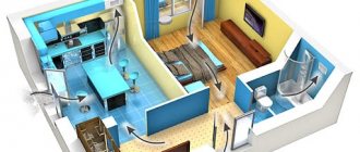
Why do you need virtual home designers?
First of all, builders, architects and interior designers use software designed for designing models of residential buildings, interior filling of rooms and arrangement of local areas. Program parameters for designing a convenient and comfortable home allow you to make changes, changing the building model, the location of rooms, and correcting defects; on paper this will be much more difficult. Other designer functionality includes:
- Selecting the optimal options for the location of the house on the site.
- Selection of the correct configuration and size of the roof, openings for doors and windows.
- Creation of a unique house model and interior space layout.
- Selection of building materials taking into account the climate, weather and characteristics of a particular region.
- Drawing up interior compositions that will suit all residents of the house.
- Correct location of swimming pools, gazebos, patios, and playgrounds in areas near houses.
- Quickly mastering the skills of working in the program allows novice designers and builders to understand the principles of drawing up drawings and planning rooms.
Using programs for virtual construction of a house model will allow builders who want to build their own housing to save money. Construction can be done by professionals, but it is specialized software that determines exactly what materials are needed for the foundation, walls, roof, and interior floors.
Adjusting results
In order to obtain a more accurate calculation, you need to take into account as many factors as possible that reduce or increase heat loss. This is what the walls are made of and how well they are insulated, how large the windows are and what kind of glazing they have, how many walls in the room face the street, etc. To do this, there are coefficients by which you need to multiply the found values of heat loss in the room.
The number of radiators depends on the amount of heat loss
Window
Windows account for 15% to 35% of heat loss. The specific figure depends on the size of the window and how well it is insulated. Therefore, there are two corresponding coefficients:
- ratio of window area to floor area: 10% - 0.8
- 20% — 0,9
- 30% — 1,0
- 40% — 1,1
- 50% — 1,2
- three-chamber double-glazed window or argon in a two-chamber double-glazed window - 0.85
Walls and roof
To account for losses, the material of the walls, the degree of thermal insulation, and the number of walls facing the street are important. Here are the coefficients for these factors.
Thermal insulation level:
- brick walls two bricks thick are considered the norm - 1.0
- insufficient (absent) - 1.27
- good - 0.8
Presence of external walls:
- interior space - no losses, coefficient 1.0
- one - 1.1
- two - 1.2
- three - 1.3
The amount of heat loss is influenced by whether the room is located on top or not. If there is a habitable heated room on top (the second floor of a house, another apartment, etc.), the reduction factor is 0.7, if there is a heated attic - 0.9. It is generally accepted that an unheated attic does not affect the temperature in any way (coefficient 1.0).
It is necessary to take into account the characteristics of the premises and climate in order to correctly calculate the number of radiator sections
If the calculation was carried out by area, and the ceiling height is non-standard (a height of 2.7 m is taken as the standard), then a proportional increase/decrease using a coefficient is used. It is considered easy. To do this, divide the actual ceiling height in the room by the standard 2.7 m. You get the required coefficient.
Let's do the math for example: let the ceiling height be 3.0m. We get: 3.0m/2.7m=1.1. This means that the number of radiator sections that was calculated by area for a given room must be multiplied by 1.1.
All these norms and coefficients were determined for apartments. To take into account the heat loss of a house through the roof and basement/foundation, you need to increase the result by 50%, that is, the coefficient for a private house is 1.5.
Climatic factors
Adjustments can be made depending on average winter temperatures:
- -10°C and above – 0.7
- -15оС — 0.9
- -20оС — 1.1
- -25оС — 1.3
- -30оС — 1.5
Having made all the required adjustments, you will receive a more accurate number of radiators required to heat the room, taking into account the parameters of the premises.
But these are not all the criteria that influence the power of thermal radiation. There are also technical subtleties, which we will discuss below. Date: September 25, 2022
What does thermal conductivity depend on?
Heat transfer depends on factors such as:
- The material from which the structure is constructed – different materials differ in their ability to conduct heat. Thus, concrete and various types of bricks contribute to large heat loss. Galvanized logs, timber, foam and gas blocks, on the contrary, with a smaller thickness, have lower thermal conductivity, which ensures heat retention inside the room and much lower costs for insulation and heating of the building.
- Wall thickness - the greater this value, the less heat transfer occurs through its thickness.
- Humidity of the material - the higher the humidity of the raw material from which the structure is constructed, the more heat it conducts and the faster it collapses.
- The presence of air pores in the material - air-filled pores prevent accelerated heat loss. If these pores are filled with moisture, heat loss increases.
- The presence of additional insulation - walls lined with a layer of insulation on the outside or inside have heat loss values that are several times less than those that are not insulated.
In construction, along with the thermal conductivity of walls, such a characteristic as thermal resistance (R) has become widespread. It is calculated taking into account the following indicators:
- thermal conductivity coefficient of wall material (λ) (W/m×0С);
- thickness of the structure (h), (m);
- presence of insulation;
- material moisture content (%).
The lower the thermal resistance value, the more the wall is susceptible to heat loss.
Thermal engineering calculations of enclosing structures for this characteristic are performed using the following formula:
R= h/ λ; (m2×0С/W)
Example of calculating thermal resistance:
Initial data:
- the load-bearing wall is made of dry pine beams 30 cm (0.3 m) thick;
- thermal conductivity coefficient is 0.09 W/m×0С;
- calculation of the result.
Thus, the thermal resistance of such a wall will be:
R=0.3/0.09=3.3 m2×0С/W
If the obtained value is equal to or greater than the standard value, then the material and thickness of the wall structures are chosen correctly. Otherwise, the building must be insulated to achieve the standard value.
If there is insulation, its thermal resistance is calculated separately and summed up with the same value of the main wall material. Also, if the material of the wall structure has high humidity, the appropriate thermal conductivity coefficient is used.
To more accurately calculate the thermal resistance of a given structure, similar values for windows and doors facing the street are added to the result obtained.