Why is the return hotter than the supply?
When heated, the liquid increases in volume, the excess enters the expansion tank. Since the heating system is completely filled with liquid, the hot coolant displaces the cold coolant, which returns to the boiler, where it is heated.
Interesting materials:
How long can stool be stored on Calprotectin? How long can flounder be stored in the refrigerator? How long can Nazivin drops be stored after opening? How long can crucian carp be stored in the freezer? How long can French fries be stored? How long can kefir be stored outside of the refrigerator? How long can bread be stored in the refrigerator? How long can bread be stored? How long can hops be stored? How long can Chinese tea be stored?
Heating system return and design methods
Radiators used in heating are made using excellent technologies from different materials, known varieties are steel panel, bimetallic (sectional) made of steel and aluminum, tubular, slightly reminiscent in appearance of old cast-iron radiators. For connection, three methods are used to connect their outlet pipes to pipes.
Lower
In modern cottage-type houses or dachas, it is fashionable to use heating of rooms with heated floors without the use of radiators that degrade the aesthetic appearance of rooms and take up a certain area. Most often, a combination of two methods of heating rooms using floors and radiators is used, while in order to level the floor levels on the entire floor, the pipeline leading to the radiators is placed in a screed. Pipe outlets are mounted from the floor or wall at a low height, to which the radiator is then connected using an N-shaped unit (binoculars). In addition to ease of connection, this liner has an aesthetic appearance, and when placed in the walls it creates additional advantages when cleaning rooms and washing floors.
A special bottom connection unit is used in one-pipe and two-pipe distributions; one of the single-pipe varieties, “Leningradka”, used for horizontal placement, has also become widespread.
Schemes with lower piping, despite their aesthetic appearance, have a significant drawback, which is weak heating of the upper part of the radiator and, accordingly, 20% less heat transfer. To eliminate this phenomenon, some lower connection units have an external bass-pass connected to the upper pipe - this is how more efficient carrier liner.
On our website there is a separate article about Connecting bimetallic heating radiators; there is a lot of useful information not only about bimetallic radiators
Rice. 11 Where is the supply and return in a heating system with bottom supply
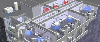
Connection diagrams for boilers, radiators, piping in home heating
You can make a heating system for your home yourself if you have the skills to do plumbing and construction work. In other words, you need to be able to solder pipes, cut them, connect them, and also tighten nuts, know the purpose and technical characteristics of the equipment used, have an understanding of hydraulics and heating engineering, and much more...
Then, using standard proven schemes and solutions, you can create a heating system for a small house only with your own hands.
But if you don’t have the skills to do the work, you will have to watch how specialists make the heating system. At the same time, it is also highly advisable to familiarize yourself with the basic rules for creating a system, equipment layout diagrams, etc., in order to monitor the progress of work and eliminate errors in a timely manner, if any are made.
Below are some nuances of creating a heating system in a private home, which you should always pay attention to first. Let's start with connecting the boiler, since many mistakes are often made in the boiler room.
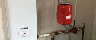
Connecting a wall-mounted boiler
Wall-mounted boilers are usually automated; they contain two important elements of the heating system:
- safety group, which usually consists of an air valve, pressure gauge, emergency overpressure valve;
- circulation pump, which ensures the movement of fluid in the heating system;
Therefore, connecting a wall-mounted boiler is the simplest; it should be done according to the following scheme (we consider the direction “from the boiler”):
Supply: – tap with American connection for connecting the boiler; - transition fitting for pipes - American.
The tap is required and is placed immediately in front of the boiler so that the boiler can be serviced without draining the system.
Return: - tap with American connection for connecting the boiler; — dirt filter; - tap; — a tee with an expansion tank, a shut-off valve, a drain and fill valve for the system. - transition fitting for pipes - American.
A dirt filter is a mandatory element of any heating system. It is installed with the sump facing down, or, in extreme cases, horizontally. Dirt from the system will accumulate in the filter and is periodically removed from the sump. When installing, you must observe the direction relative to the stream.
The taps near the filter are required; only by closing both taps can you service and clean the filter.
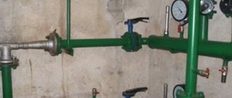
Next, let's look at the piping of a floor-standing boiler. It is more complicated, since a floor-standing boiler does not have a safety group and a pump. Therefore, they are installed independently, like elements of a boiler room.
Safety group, circulation pump, expansion tank
For the safety group, it is better to purchase a special tee and mount the devices listed above on it. It is important to select devices in accordance with the parameters of the heating system, usually the maximum pressure is 4 MPa, the operating pressure is 1.5 - 2.0 Atm.
The pump is purchased according to the characteristics of the system. For an ordinary small house (up to 150 sq. m.), a circulation pump with a pressure of up to 4 m (0.4 atm) will always be sufficient for the heating system (often for radiators up to 250 sq. m.)
Accordingly, the pump is marked 25 - 40, where the first number indicates the thread diameter of the connection pipes, in this case 25 mm - 1 inch, but it can be 32 mm or more. The second number 40 is a designation of the pressure created - up to 0.4 atm, and therefore, indirectly, the power of the pump.
Each circulation pump has a rotation speed adjustment in at least 3 positions, which will determine the volume of liquid pumped and the actual power consumption.
In the first adjustment position, the circulation pump 25-40 will consume no more than 30 W of electricity. More often, for a properly designed heating system in an insulated house up to 150 sq. m. There will be enough thermal energy that can be supplied by this pump at first speed.
Equipment with open gravity system
With an open gravity system, the entire load falls on the open expansion tank.
It performs the following functions:
- takes away excess amount of coolant;
- compensates for increased pressure;
- removes air and hot steam when the coolant boils.
The volume of the tank should not be less than 10 percent of the coolant volume. More is possible. Install it at the top point of the circuit, where the accelerating manifold ends. From the tank, the filling goes back to the heat exchanger, with a slope that ensures that air pockets are removed and the coolant moves by gravity.
Cold water is usually poured through an open expansion tank to compensate for evaporation.
Comparison results
Summing up, it becomes clear that a single-pipe distribution system with a return has the greatest prospects , especially for multi-storey buildings. Ease of installation, low cost and a small number of communications still have an advantage over a two-pipe with supply.
However, do not forget that using a two-pipe circuit, it is possible to regulate the heating temperature for each device separately.
Source
Horizontal intra-apartment wiring
In many new buildings it is possible to find a relatively exotic scheme: outlets from risers enter the apartment, allowing heating devices to be installed to suit any layout. Along with this, the diameter of the risers and outlets is selected so that the horizontal contour in your apartment does not set the heating parameters in the apartments higher or lower.
In addition to an arbitrary layout, a horizontal circuit with an output and one input allows for the establishment of thermal energy metering. As the price of heating per square meter increases, the installation of meters becomes more and more urgent.
How to correctly install heating in the horizontal circuit of a separate apartment?
According to the author’s humble point of view, the most reasonable thing would be to adapt the Leningrad or barracks wiring diagram to this situation.
Penalty for excess return flow Blog of a heating engineer
Hello, dear readers of the blog teplosniks.ru! On my blog I previously wrote about overheating of the heating return. The most unpleasant thing in such a situation is when you are given a specific bill for overheating in the return pipeline. No one wants to part with money, especially when the volume of heat consumption is calculated in the form of penalties. You have to pay the meter and more. So, how exactly does the energy supply organization calculate the fine?
The first point determines the contractual flow of network water through the heating unit. It is determined by the formula:
where Qdog is the heat load for heating under the contract (this figure must be in the contract, look). Let's take a specific figure of 0.332 Gcal/hour.
C—heat capacity of water, kcal/kg °C
t1 — supply temperature according to schedule, °C
t2 — return temperature according to schedule, °C
We substitute specific numbers. Usually the temperature graph is 150/70 °C (but it can also be 130/70 °C and 105/70 °C, etc.). In our case t1 = 150°С; t2 = 70°C. The heat capacity of water can be taken to be unity, C = 1. In fact, the heat capacity will be slightly different from unity, but we don’t need such super-precision. So, we calculate the figure, the consumption of network water, which should be according to the contract.
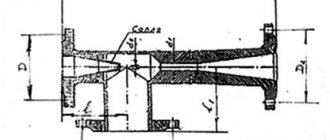
Terminology
First, to avoid confusion, let's define the terms.
In addition: the elevator unit brings the pressure and temperature of the coolant to optimal values for the operation of the heating system. Thus, the difference between the supply and return lines of the highway reaches 4 kgf/cm2, while at the same time, a difference of 0.2 kgf/cm2 is sufficient to circulate water through the batteries.
So, what specific wiring diagrams for heating systems can be used in multi-apartment buildings? What specific elements do they include?
All about plumbing
Tips for using your heating system
Navigation
Glossary of terms
Publication rating:
Hello. Today I want to talk about some details, ignorance of which can cause many problems.
So, after completing the installation of the heating system, first of all, try to carefully examine all the mounted components, radiators, and boiler. It often happens that we missed something, or made some mistake. If we notice something, it’s better to fix it right away, don’t wait for something to happen.
Powering the system
If everything is in order, then you can start powering the system. What's the best way to do this?
In general, it is correct to feed it through the return line (a pipe that removes cooled coolant from the radiators), which is what we will do. To do this, you need to close all the valves on the radiators, then gradually add water to the system, go to the end radiators (those that are the last or farthest from the boiler), and open the valve on the return line, while simultaneously opening the Mayevsky valve (air vent from the radiator). After water flows from Mayevsky’s tap, open the radiator supply tap (of course, before closing the air vent). Next, we repeat this procedure with the next radiator, moving towards the boiler.
When all the radiators are powered, we check that the air is vented at the top point of the system (there should be a safety group, or just an air vent, depending on the type of system), then we turn on the pump, and after 5-10 minutes, we go and go through each radiator, venting the air through the vent valve (before venting the air, be sure to close the supply valve, open it after venting), and refuel the system as necessary. This will have to be repeated until there is no air left in the radiators.
Risers
The distribution of coolant through heating devices in a private house is possible horizontally and vertically (stand-up). In multi-apartment buildings in different areas, these schemes are side by side: if the bottling is always a horizontal layout, then the riser is a vertical layout.
What is useful to know about risers in an apartment building?
- On no floor, except for the top floor in a house with bottom filling, should radiator inserts interconnect paired risers. If you insert a heating device between the supply and return risers on the fifth floor of a ten-story building, the inhabitants of the upper floors will freeze: the circulation above the insertion will actually stop.
- In buildings of new projects, one of the paired risers is often made idle (in other words, it is not connected to the batteries). The heating wiring diagram with single risers allows the transfer of paired risers from the basement, without the participation of residents. It is enough just to install a relief valve on the idle thread instead of a plug and move it to the discharge: the air plug will completely fly out at the water front.
- In stalinkas, two radiators are often connected to one riser in parallel, without changing the diameter. Along with this, the riser itself is a jumper between their connections. Such
The heating system wiring is fully operational, but only with a huge (DN25) diameter of the connections.
Practical consequence: if you want to replace the interior wiring yourself, either use heating pipes of the same diameter, or throttle the jumper. The instructions are due to the fact that with a jumper diameter of 25 mm and connections with a nominal diameter of 15-20, the batteries will simply be cold.
Example 5
The heating system is closed. Heat meter T21 Compact DN65 installed. The red graph is the coolant flow rate at the supply (channel V1). Control flow meter on the return (channel V2, green graph). The counter has been operational since March 20, 2013.
Problem: The error in some places goes beyond 5-10%.
Analysis: Probably the system is not closed, given the maximum error of the devices is 4%, the house consumes 1-5% of the flow. The graph shows mirror-symmetrical costs, which raises suspicion that the manufacturing plant’s engineers are already looking into this defect.