Creating artificial heating of a room to compensate for heat losses and maintain the temperature at a comfortable level is important not only for a country house, but also in urban environments.
Topping up the heating system is one of the most important measures to maintain the functionality of the equipment in use.
Operating principle of recharge
Operating principle of recharge
Makeup is needed to restore volume or pressure in the heating system. When the device adds working fluid, it automatically stops after the main indicators are equalized. Most often, the equipment is connected to a cold water supply, and liquids are drawn from there. Another option is a storage tank, where you have to manually replenish the supply, and it is usually intended for synthetic products.
Two types of heating make-up have been developed:
- Manual. Designed for small closed circuits where small pressure surges occur. A pressure gauge is used to detect leaks in a timely manner. When the pressure drops, by opening the corresponding tap, water is supplied, thereby replenishing the losses. The liquid flows between the pipes either independently or using a special pump. Budget solutions have an overflow pipe in the expansion tank; when the water reaches this mark, the liquid supply is stopped. The only disadvantage of such a device is the need for constant supervision and experience in performing the procedure.
- Automatic. The equipment independently processes data from the pressure gauge. When a critical point is reached, the working fluid supply valve opens. As with manual control, the pressure in the cold water supply is sometimes not enough, so pumps are installed. When water losses in the heating system are restored, the valve closes. The advantage over the manual method is the automation of the process. When you leave home for a few days, you don’t need to worry that the boiler will overheat or break down. The disadvantage is the increase in electricity costs.
The need for recharge does not always arise. To prevent the equipment from being idle, it can be used for other purposes. It is capable of filling the pipeline with water or synthetic coolant. The equipment will come in handy at the beginning of the heating season, when pressure testing of the entire system is carried out. The device is also suitable for flushing pipes, discharging water or filtering it from coarse particles.
Why do you need heating make-up?
The efficient operation of a modern heating system is based on maintaining a stable operating pressure of the coolant. Even in systems that have been tested for leaks, microscopic leaks that are invisible to the naked eye can be observed.
Among other things, a certain amount of coolant leaks from the heating system during the process of removing air bubbles using the Mayevsky tap, and can also seep through the seals of the installed circulation pumping equipment.
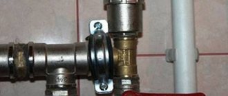
Thermal unit with make-up
A small part of the coolant is lost in the contour joints. General fluid losses can have a significant negative impact on the performance of the heating system.
Most often, tap water is used as a heat carrier, and recharging the operating heating system through the main water supply helps compensate for the loss of such liquid as effectively as possible.
Elements of the make-up device
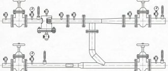
The recharge scheme for heating networks will depend on the hourly productivity of the standard recharge. For large main heating networks, in which the standard recharge is hundreds and sometimes thousands of cubic meters of water per hour, the complex includes: a water tank, chemical water treatment, automation, electric pump and shut-off and control valves. When performance decreases, the number of circuit elements can be significantly changed.
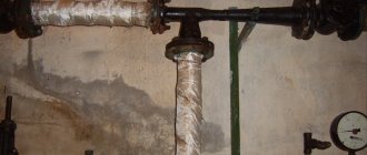
System recharge unit
Boiler gearbox
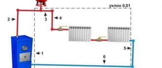
The reducer is installed on the return pipeline in front of the boiler to supply make-up water to the network circuit. Water from the city water supply flows through the valve when the pressure in the network pipeline drops due to leaks or release of an air lock. If the diagram provides for the installation of a circulation pump, then it is installed second. Otherwise, the operation of the entire heating system may be disrupted.
The gearbox operates automatically without maintenance personnel. Sometimes this is not always convenient, since it is impossible to control the leak, and its size can reach emergency proportions. Therefore, many users prefer manual recharge mode or install systems with alarms for high leakage levels.
Pump group
One or more pumps supply make-up water in front of the boiler units at a pressure higher than that in the return network water. The pump is activated by a pressure sensor and supplies water from the make-up water tank.
There are schemes with a submersible pump that can take water from a well or well. The pump group is calculated based on the hourly productivity of the standard make-up; the number of electric pumps must be at least 2, one of which is a reserve one.
Diagram of a heating system with make-up
Actuating mechanism
It is installed to control the valve on the make-up line. Usually it is included in the make-up unit, consisting of a shut-off and check valve. It has electrical contacts for sending a signal to control the pump. The mechanism is adjusted to the permissible operating pressure. The actuator is usually a valve with an electric motor.
When the pressure in the return drops below the permitted value by 10%, the electric motor begins to rotate, opening the make-up valve, water from the water tank or from the municipal water supply with a pressure higher than in the return flows into the internal heating circuit.
As it is filled, the pressure reaches the operating value, the sensor gives a signal to close the valve, the electric motor of which begins to rotate in the opposite direction.
2.6. Main and auxiliary equipment of heating plants
The water supplied to the heating network for the needs of consumers at the CHP plant is heated in network heaters of turbine units, in peak heaters and in peak water heating boilers, which belong to the main heating equipment of the CHP plant. Auxiliary heating equipment includes: heating network make-up unit, network pumps, storage tanks, recirculation pumps of hot water boilers, etc.
Peak water heating boilers (PHBs) are designed for installation at thermal power plants to cover peak heating loads.
Peak hot water boilers are usually installed in separate rooms at large CHP plants or in the main building at small CHP plants. The fuel for these boilers is mostly fuel oil or gas. Due to their low use throughout the year, peak boilers are simple in design and inexpensive. The building can be carried out only for the lower part of the boilers, while their upper part remains in the open air. Before the CHP plant is put into operation, hot water boilers can be used for temporary centralized heat supply to the area. The network water is heated sequentially in network heaters to 110÷120C, and then in the PVC to a maximum of 150C.
To avoid corrosion of the boiler metal, the temperature at its inlet must be no lower than 50÷60C, which is achieved by recirculating and mixing hot and cold water. The calculated efficiency of hot water boilers using gas and fuel oil reaches 91÷93%. Coal-based PVCs are produced and used. They have their own dust treatment, smoke exhausters and other equipment.
Steam-water heaters for heat treatment plants
are designed for heating network water with steam from turbines or boilers through reduction-cooling units (abbreviated ROU).
Network pumps
serve to supply hot water through heating networks and, depending on the installation location, are used as first lift pumps supplying water from the return pipeline to network heaters; second rise to supply water after network heaters to the heating network; recirculation installed after peak water heating boilers.
Network pumps must have increased reliability, since interruptions or malfunctions in the operation of pumps affect the operation of thermal power plants and consumers.
The main feature of the operation of network pumps is fluctuations in the temperature of the supplied water over a wide range, which in turn causes a change in pressure inside the pump. Network pumps must operate reliably over a wide flow range.
Typically, network pumps are centrifugal, horizontal, driven by an electric motor.
Manual recharge scheme
The simplest option for filling the system is implemented in 90% of double-circuit wall-mounted boilers, where a cold water supply pipe is a priori connected. A manual valve is installed inside the housing, connecting this line with the heating return line. Often, a boiler feed tap is found on solid fuel heat generators with and without a water circuit (for example, heating units of the Czech brand Viadrus).
Reference. On some models of gas heaters equipped with a DHW heat exchanger (in particular, Beretta), instead of a manual tap, manufacturers install an automatic make-up valve with an electromagnetic drive. If the coolant pressure drops below 0.8 Bar, the boiler itself draws water to the required level.
In wall-mounted double-circuit heat generators, the make-up valve is located at the bottom, where the pipelines are connected
. To assemble a classic make-up unit suitable for any type of system, you will need the following parts:
- tee with side outlet DN 15-20, corresponding to the material of the heating main pipe - fitting for metal-plastic, polypropylene, and so on;
- poppet (spring) check valve;
- ball valve;
- couplings, fittings.
The purpose of the check valve is to prevent water from the heating network from flowing back into the water supply system. If we are talking about pumping antifreeze using a pump, you cannot do without a valve. The fittings are installed in the order listed:
- The tee cuts into the heating return after the circulation pump.
- A check valve is connected to the outlet pipe of the tee.
- Next is a ball valve.
Advice. If there is no fine filter at the entrance of the water supply to a private house, it is advisable to provide one on the make-up line. The element will protect the heating system from the entry of fine sand and rust particles that accumulate on the check valve plate and in the seats of three-way valves.
The operating principle of the unit is simple: when the tap is opened, water from the centralized main flows into the heating pipelines, since its pressure is higher (4-8 Bar versus 0.8-2 Bar). The filling process of a closed system is monitored by a boiler or safety group pressure gauge. If you accidentally exceed the pressure, use the Mayevsky tap on the nearest radiator and bleed off excess water.
To control the amount of coolant in the expansion tank of an open heating network located in the attic of the house, the tank must be equipped with 2 additional tubes with a diameter of ½ inch:
- The control line, ending with a tap in the boiler room, cuts into the side wall at approximately half the height of the tank. By opening this valve, you can determine the presence of water in the tank without climbing into the attic.
During the replenishment process, air bubbles escape through the tank lid, the maximum level is monitored by the flow of water from the upper fitting through the pipe - The overflow tube is inserted 10 cm below the tank lid, the end is discharged into the sewer or simply onto the street under the roof overhang. Being in the furnace room and opening the feed tap, you should see this pipe; when water flows from there, filling stops.
Comment. If you are interested in calculating the minimum volume of the expansion tank, follow the dedicated link.
The circuit with a check valve and shut-off valve is also applicable for filling solar systems (solar collectors) and geothermal circuits of heat pumps with antifreeze. How to use the boiler make-up valve is described in the video:
Calculation of the heating network make-up deaerator.
rice. 2.6. Design diagram of a vacuum deaerator.
opodpvd
2.10.
Calculation of the HDPE system. 424 dr4525
dr5626 dr6727 dr7't Fig. 2.7. Design diagram of the HDPE system.
6t5tpsouupltdvut'prtnevozvtt7oetktoo
2.11. Determination of steam flow to the turbine and checking its power . 3. Thermal calculation of HDPE and optimization of its characteristics on a computer. Initial data for PND 4:
- heated water consumption Gw=0.84102=85.7 kg/s;
- inlet water temperature tв1=136 оС;
- heating steam pressure P=0.52 MPa;
- saturation temperature of heating steam tn=153 oC;
- temperature difference of the heater t=2 оС
- latent heat of vaporization r=2102 kJ/kg;
- average heat capacity of water av=4.19 kJ/kg oC;
- internal diameter of pipes din = 0.018 m;
- pipe thickness =0.001m;
- thermal conductivity of brass st = 85 W/m K;
- distance between partitions H=1 m;
- water speed c=2 m/s;
- price of a ton of standard fuel Ct.t.=60 $/t.t.e.;
- specific cost of the heater surface kF=220 $/m2;
- heat extraction coefficients j+1=0.4 and j=0.267;
- number of hours of use of installed capacity hsp = 6000 h;
- Boiler efficiency ka=0.92;
- Heat flow efficiency tp=0.98.
ooo Physical properties of water at tвf.
322
Physical properties of the condensate film at tn.
3222oooo2ntr
4. Determination of heat value coefficients. Calculation of power change factors. We will calculate the value coefficients of the heat of the extractions using the formula: Analysis of technical solutions using the CCT of extractions.
- Reducing the temperature pressure in HPH 6 by 1 °C.
- Installation of superheated steam cooler.
- Installing a drainage pump on HDPE 2.
- Installation of the expander.
- Increase in pressure loss in the extraction pipeline to HDPE 4 by 2 times.
ooo
- Installation
of drainage cooler on PVD 6.
5. Calculation of technical and economic indicators. 6.Selection of auxiliary equipment for turbine installation.
- We select feed pumps to supply feed water at the maximum power of the installation with a margin of 5%:
pnpv
- We select condensate pumps based on the maximum steam flow into the condenser with a margin:
knc
- We select drainage pumps without reserve (reserve - cascade drainage) type KS-32-150 (PND 6).
- We select low-pressure heaters of type PN-200-16-7 I in the amount of 4 pieces.
- Three high-pressure heaters, type PV-425-230-35-I.
- We select deaerators with a deaerator column type DP-500M2 and a deaerator tank type BD-65-1.
Conclusion.
o2
Literature.
2
Automatic make-up unit
If you are firmly confident in the reliability and quality of the system, you can install an automated circuit that adds water from the cold water pipe. What you need to buy:
- pressure reducing valve (simpler - reducer);
- 3 ball valves;
- 2 tees;
- pipe for the bypass device.
Important point. The water entering the reducer must be pre-cleaned with a coarse strainer, otherwise the valve will quickly become clogged. If such a filter is not provided at the entrance to the building, install it in front of the make-up unit.
In this diagram, the pressure gauge shows the pressure on the side of the heating network; bypass and taps are needed to service the recharge module
The main executive element of the circuit - the gearbox - consists of the following parts:
- fine filter on the inlet pipe;
- spring seat valve with rubber seals;
- pressure regulator handle with a printed scale, range – 0.5…4 Bar (or higher);
- manual shut-off valve;
- check valve at the outlet.
Note. There are more expensive models of make-up reducers with a built-in pressure gauge that measures the pressure on the side of the heating system. Since this device is already in the safety group or boiler, there is no point in spending extra money and duplicating it. The exception is the situation when the make-up is installed far from the heat source (read the next section).
As you can see, the pressure reduction machine already contains all the necessary elements - a filter, a check valve and a regulator. All that remains is to assemble a simple circuit with a bypass and service taps designed for removing and servicing the gearbox.
Operating the valve is simple - use the regulator to set the minimum pressure threshold in the heating network, open the direct line taps, and close the bypass.
Advice. If you plan to install a coarse filter in front of the gearbox, provide an additional service tap in order to clean the mesh without turning off the water in the entire house.
To organize the automatic addition of antifreeze to the system, you can adapt a “hydrofor” - a water station with an electric pump designed for water supply from a well. The pressure switch of the unit must be reconfigured to a minimum pressure of 0.8 Bar, a maximum pressure of 1.2...1.5 Bar, and the suction pipe must be directed into a barrel with non-freezing coolant.
The appropriateness of this approach is highly questionable:
- If the “hydrofor” works and starts pumping up antifreeze, you will still have to look for and eliminate the cause of the problem.
- If the owners are absent for a long time, replenishment will also not save the situation in the event of an accident, since the size of the container is limited. The pumping station will extend the heating operation for some time, but then the boiler will turn off.
- Placing a large barrel is dangerous - you could flood half the house with toxic ethylene glycol. Non-toxic propylene glycol is too expensive, as is spill cleanup.
Examples of organizing automatic refueling from containers of different capacities
. Conclusion. Instead of additional pumps and automatic gearboxes, it is better to purchase an electronic unit of the Xital type. After a relatively inexpensive installation, you will be able to control the heating operation via a cell phone or computer and quickly respond to emergency situations.
How is the make-up line installed correctly?
In private households, as a rule, a gravity heating system is installed, so the design feature of the make-up unit is the mandatory presence of elements presented:
- a ball valve involved in supplying water from the water supply to the heating system circuit;
- a purification filter for the coolant, represented by water, to remove major contaminants;
- a check valve that prevents the movement of liquid from the heating circuit into the water supply system.
It is important to remember that hot water from the heating system should not flow into a cold pipeline.
The movement of the coolant in the opposite direction is most often the result of insufficient pressure in the central water supply system or failure of shut-off valves.
How to connect to the heating system
With a closed circuit, there is not much difference where to connect the make-up pipeline - to the supply or return. We recommend using the classic proven method - the insertion point should be located on the return line next to the boiler, after the circulation pump and expansion tank. Causes:
- the unit is located in the combustion room, next to the equipment and instruments;
- pumping water into the return line is immediately reflected on the pressure gauge installed in the supply behind the boiler;
- the insert is located at the lowest point, the flow is distributed in 2 directions - into the boiler and radiators, the air is squeezed out evenly.
Classic scheme for inserting a recharge module
The piping of solid fuel units involves the installation of a condensation protection circuit with a three-way valve. You cannot make makeup in front of this valve - cold water will immediately close it and the boiler pressure gauge will begin to lag in readings. Cut inside the circuit, between the 3-way valve and the heat generator.
In a similar way, the make-up flows into the return line of the open system. The second option is to add coolant directly to the tank; the disadvantage of this method is to lay the supply pipe into the attic.
Recharge
As a rule, heating is fed by connecting to a cold water supply system, but in some cases, feeding is done using a storage tank.
In an open heating system
A decrease in the volume of coolant in an open heating system is signaled by an expansion tank, which is mounted at the top point of the installed structure.
The gravity system is recharged when the level of coolant in the tank decreases and there is no sufficient pressure inside the control pipeline.
Diagram of the heating system recharge unit
In order to prevent increased coolant consumption, it is necessary to install shut-off valves that are activated at the moment of control opening of the tap.
In closed heating circuit conditions
The best option for arranging a closed-type heating system is represented by the installation of an automatic feeding unit with various types of fittings. It is best to use a reducer that has a built-in filter, check valve, valve and pressure gauge that allows you to monitor pressure levels.
When using ordinary main tap water as a heat carrier, it is advisable to ensure the installation of a high-quality integrated filter device, which will extend the life of the entire heating system.
The feeding device is most often mounted on a bypass with all threaded connections packed and mounting taps soldered in, after which the fully assembled unit is installed.
Finally, about the safe addition of coolant
When filling water or partial replenishment, follow our recommendations:
- Replenish the heated system slowly by opening the valve a quarter of the lever stroke. In this way, it will be possible to avoid the formation of air locks and protect the boiler heat exchanger from temperature shock.
- Refill from scratch with the heat generator not working and the circulation pump turned off.
- Check the pressure in the expansion tank and go through all the radiators, opening the Mayevsky valves to release air.
- If your boiler is equipped with modern electronics, be sure to study the instructions regarding make-up. Often it is necessary to activate a special service mode in the unit.
- Excess pressure is easily released through the nearest air vent.
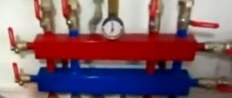
The complex system make-up module can be connected to a hydraulic separator and a comb
Reference. Cast iron heat exchangers easily crack from sudden temperature changes, and steel fireboxes become covered from the inside with condensation. The latter mixes with soot and forms a dense coating.
Injecting antifreeze with a hand pump does not have any pitfalls. Pressure testing units are equipped with their own pressure gauge, which allows you to monitor the current pressure at the insertion point.
Example of an automatic make-up system
Despite the rich selection of systems that really deserve the attention of device consumers, in fact, there are not so many. Any manufacturer in the accompanying documentation for the device indicates the recommended connection diagram for the feed valve.
Most often, the design of such a device is self-sufficient and includes a basic filter water treatment and a check valve, as well as a valve for manual replenishment.
Heating system with automatic control of the make-up valve
Despite the fact that an automatic heating system make-up valve can simply be installed in the area from the plumbing system to the heating circuit, it is advisable to separate it on both sides with standard shut-off valves, represented by ball valves.
This feature of the automatic replenishment system is due to the need to periodically inspect and maintain the unit during operation.
A definite advantage of the control unit is its user-friendly interface, convenient for all consumers, as well as the ability to manually recharge the system in the event of an emergency.
Underfloor heating is becoming increasingly popular. Connection diagram for a heated floor to a heating system - an overview of important points.
Why you need a distribution comb in a heating system, you will find out by reading this material.
Installation features
The direction of the water must coincide with the direction of the arrow on the body of the device.
The valve is placed on the pipe so that the direction of the liquid coincides with the direction of the arrow. The filter plug is directed downward, and the adjustment screw must be accessible for use. The pressure gauge dial rotates to make it easy to read the values.
The winding material is used rationally so that excess does not fall into the lumen of the gearbox. Boiler feed in the form of a valve should not depend on main loads (compression, torsion, bending, vibration). For this purpose, additional supports or compensators are installed.
The mismatch between the axes of the pipelines should not be more than 3 mm for a length of 1 m. For longer lengths, 1 mm is added for each linear meter. The make-up circuit is connected to the pipeline near the expansion tank.
Why make up the heat supply system?
Even in the most advanced heating systems with high-quality piping of the boiler and heating network, it is impossible to completely avoid water leaks from the system.
Therefore, a make-up unit is installed, and the owner of the boiler needs to know in what case it is permissible to use ordinary tap water to feed water-heating boilers.
The main reasons for reducing the volume of water in the internal circuit of the boiler can be called:
- Technological discharge of coolant during the process of heating the boiler from a cold state caused by thermal expansion of water and the need to reduce pressure.
- Operation of Mayevsky cranes.
- Carrying out emergency or preventative repairs.
- Emergency leaks from the boiler due to rupture or corrosion damage to the internal heating surfaces.
- Safety valve leaking during emergency water release.
- Violation of the boiler maintenance schedule.
- Poor water quality and scale formation in pipes.
- Poor quality of installation of the heating circuit.
Boilers are fed with raw water using a special unit, which usually comes with the boiler. If it is not available, the manufacturer must provide information to the buyer about the required piping scheme, calculation of the minimum equipment performance and the necessary equipment specifications.
A normal leak in a closed system is 0.75% of the actual volume of water in the network, heating devices and boiler circuit, and in open systems 1.2 of the calculated hourly volume for DHW needs is added to this value. For a powerful hot water and steam boiler, the makeup water must undergo preliminary chemical treatment.
Recharge calculation
The calculation of the required volume of added water is carried out in accordance with SNiP 41-02-2003 “Heating networks”.
In closed heating circuits, a coefficient of 0.075 is used to the total volume of energy in the networks and pipelines connected to them.
A multiplier of 0.05 is applied to the volume to calculate the make-up of areas that are more than 5 km from the boiler house, in open and closed systems.
In open pipelines, a coefficient of 0.12 is taken to the average liquid flow rate for hot water supply and the actual volume of energy carrier in the pipes is added with a multiplier of 0.075.
Operating principle and types of node control
The most important task of the make-up unit is the ability to supplement the missing part of the coolant into the heating system, which will normalize the operating pressure.
Today, there are a couple of options for replenishing the volume of lost thermal fluid:
- Manual control is most convenient when servicing a small heating system, in which it is possible to independently control the pressure level in strict accordance with the pressure gauge. In this case, the supply of coolant occurs by gravity or using make-up pumping equipment.
- The automatic make-up mode automatically turns on when the pressure level inside the system drops below the established limits. In this case, the valve is activated to replenish the heating system and the flow hole is opened with a forced supply of coolant. After equalizing the pressure indicators, the valve closes, and the standard shutdown of the pumping equipment is performed.
Despite the convenience of the second option, it is very important to remember that the automatic recharge mode requires the mandatory inclusion of an additional element in the system that requires electrical supply. In case of frequent power outages, it is advisable to duplicate the automatic control of the manual recharge lever.
The simplest gravity installation in the manual version carries out the usual supply of tap water until the excess comes out of the overflow pipe on the expansion tank, and the advantage of automation is the almost complete absence of the need to control the process of replenishing the system.
Current advice on configuration and maintenance
Whatever power supply you choose, remember, first of all, it should be safe and easy to use, made of high-quality materials. If the heating system is small, give preference to a device with the simplest possible design. The central support with moving parts and the internal compensation piston must be made of materials with a low adhesion coefficient: the risk of lime formation in the unit must be minimized. It is no secret that they are the main reason for the poor performance of the device.
Please note whether the product has a replaceable cartridge: this will greatly facilitate and speed up the process of inspecting the unit for you.
Periodic maintenance of the make-up device will help avoid malfunctions in the entire heating system.
To clean or replace the entire cartridge, proceed as follows:
- Insulate the installation.
- Unscrew the control knob located at the bottom.
- Unscrew the adjustment screw until it stops and remove the cover.
- Remove the cartridge with pliers.
- After the necessary manipulations, reassemble the device.
All that remains is to set up the equipment again and continue to enjoy the uninterrupted operation of the heating system in your home!
Make-up control
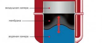
In a small-volume heating system, pressure level differences, as well as a decrease in the total amount of coolant, can usually be compensated by means of membrane tanks.
It is for this reason that adding liquid to the system is a relatively rare occurrence.
Simplification of the design involves manually turning on the pumping equipment, as well as opening and closing the make-up line. In this case, monitoring the pressure level must be systematic.
Controlled heating is more complex, but extremely efficient. It is in the automatic mode that a direct refusal to work on the “direct action” principle is assumed. There is no need to regulate the operation of the source of all generated thermal energy, or to add or subtract the resources used. This option is based on the use of a control module.
Thus, the automatic control mode is based on selecting the most comfortable temperature conditions and is more convenient, and also allows for significant savings in energy consumption.
The Italian brand of heating boilers “Beretta” has earned popularity in our country. Beretta gas boiler - types of equipment and an overview of popular models.
How to calculate heat loss at home and why it is needed, you will find out here.
The piping diagram for a solid fuel boiler is presented at the link. We will also talk about the importance of proper strapping.
Heating system make-up valve which make-up valve is needed for CO
The make-up heating system is considered the main point in the entire mechanism. To eliminate a variety of troubles, you should definitely study the device, understand the whole essence of the activity and understand the fuel substances.
Any heat supply basically begins with a boiler plant, in other words, a place where heterogeneous fuels are burned. After which the generated heat is supplied by the heat carrier through the pipes. It should be noted that coolants can be designated into more than ten types:
Water, by its very nature, is the most popular coolant.
However, the substance in question is endowed with the ability to quickly freeze when the temperature decreases.
That is why a specialized liquid called antifreeze is very often used, which, when diluted with water, significantly reduces the adverse effects on the pipeline. Coolants for centralized heating can be directed through a conventional or pumping system. The habitual direction system has the simplest structure. The pumping system is more complex. It is mostly used in closed heating.
Make-up production
The heating system's make-up valve is designed to ensure that leaks do not occur when pipe connections become loose. Due to this, constant checks, replenishment, monitoring of pressure and water volume are strictly necessary.
By following all the rules, you don’t have to think about possible accidents and other troubles.
The charging valve for the heating system will operate in automatic mode. If we look at it schematically, the structure becomes extremely clear. The make-up pump includes a specialized valve, which has a built-in membrane fabric and a spring. The spring, for its part, is held in place by this membrane tissue. At the moment of pipe pressure, these two elements are lowered, creating a specific hole that allows water to pass through. After some time, the pressure is restored again, and the membrane tissue returns to its original position.
In addition, the automatic replenishment of the heating system includes in its own structure special filters that do not allow the passage of dirty water. Each such filter has a pressure measuring device that indicates the total pressure. Likewise, the degree of contamination in the pipes can be easily determined.
The filling valve for the heating system should be installed next to the expansion tank. This is where it will have a chance to work correctly, with an accuracy comparable to a pharmacy scale.
You need to know that calculations of the distance between the boiler and the make-up must be as correct as possible.
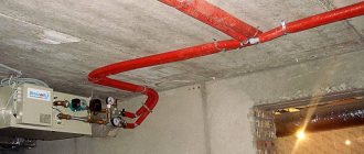
Installation of an automated heating system
Automatic recharge of the heating system and its design have a specific method of operation, which consists of several fundamental stages:
- At the moment the pressure drops to a level below the operating level, a specialized valve opens, in which the heat supply is again replenished with coolant;
- When the operating required value of the valve pressure is reached, the pumping system is switched off.
The scheme in question is very simple. The most commonly used system is the electrical system.
System simplification
The charging valve for the heating system greatly facilitates the process of filling the device. In terms of its own structural part, the mechanism under consideration has several main elements:
- A pressure reducer that maintains constant system pressure in the range from one to three atm;
- Reducing valve that perceives liquid pressure;
- A tap with a round hole, endowed with a diameter of 0.5;
- Bypass line speeding up the filling process;
- Pre-filter installed at the nodal inlet;
- Return line connecting an already assembled unit;
- Heating boiler.
The price for the heating system feed valve is set depending on the selected option. In many cases, the selected models are equipped with check valves, mesh filters, and also manual filters.
Also, the cost price is also influenced by the maximum pressure in good condition and the highest operating temperature range.
In addition, it is necessary to note the installation pressure range, which can vary in a wide variety of parameters.