The operating costs of waste oil heating boilers are among the lowest, often even lower than the cost of gas. The process of installing heating equipment is also cheap, and boilers operating on exhaust gas are comparable in reliability to their gas or diesel counterparts.
However, they still have not gained wide popularity due to the high initial cost (usually from 100 thousand rubles), the need for constant daily care, and less functional automation and controls (with the exception of extremely expensive models). However, if you understand all the advantages and disadvantages of oil boilers, the choice may well be justified.
Features of heating boilers operating on fuel oil
Such heat generators are similar in degree of automation to gas ones, but fuel for them is as common as for coal or wood ones. The combination of these qualities makes this equipment in demand in areas where centralized energy supply is represented only by the electrical network.
Oil heaters are used mainly in industrial boiler houses. Models for private homes are still much less common than diesel models.
Features of the units:
- Energy dependence.
- Electronic automation.
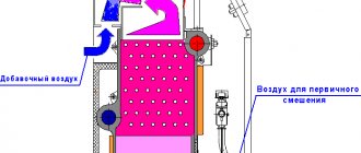
- Turbocharged combustion chamber without communication with the room. Air is sucked into the firebox by a fan from the street through the internal channel of the coaxial chimney.
- Forced exhaust removal, which allows the pipe to be positioned horizontally.
- Work only with closed heating systems equipped with circulation pumps.
Application of single-pass gas-oil boilers PKZ of the KV-GM series
This series of boilers is widely used in the reconstruction of old or construction of new boiler houses, especially in those regions where there is no natural gas. (Boilers up to 6 MW can be equipped in block-modular boiler houses.)
Boiler houses with single-pass PKZ boilers of the KV-GM series are used for heat supply to various consumers:
- Residential buildings in microdistricts and city districts
- Manufacturing enterprises.
- Oil and gas enterprises.
- Mining enterprises.
Design specifications
The parameters of the liquid fuel boiler are:
- heat performance;
- volume of the boiler tank (heat exchanger);
- maximum pressure of the working medium;
- type of fuel;
- electrical power consumption;
- efficiency;
- dimensions and weight.
The efficiency of an oil-fuel boiler is 75–85%.
The efficiency of such installations is in the range of 75–85%.
Functions
The unit heats the coolant circulating in the liquid heating system. 2-circuit models additionally provide hot water supply.
Thanks to the electronics, the following functions are available:
- programming;
- control from a smartphone;
- work with weather-dependent automation.
Operating principle
Fuel is supplied under pressure into the nozzle and is sprayed out of it to form small particles. They quickly evaporate, mix with air and ignite.
The heat from the fire and the hot exhaust heat the water in the boiler tank. Thanks to the pressure created by the circulation pump, it moves along the circuit and imparts the resulting energy to the air in the rooms through radiators.
The fuel in the boiler is atomized into small particles.
The operation of the boiler consists of alternating 2 modes:
- heating;
- expectations.
The first one ends at the moment when the sensor detects an excess of the coolant temperature and sends the controller a command to stop supplying fuel. The flame dies out and the device goes into standby mode.
After the coolant has cooled by 5°C, a start command is received and the supply of fuel oil to the nozzle is resumed.
At the same time, the electronic ignition device generates a spark, causing the fuel to ignite.
Device
The main component of the heat generator is the burner. It turns the fuel oil flow into a fuel-air mixture, which then burns here.
The burner is equipped with a normally closed solenoid valve. It is held in working position by the field created by the coil when current flows through it.
The power supply stops and the valve closes in the following cases:
- the flame has gone out and cannot be rekindled;
- there is no draft in the chimney;
- The coolant has heated above the set temperature.
Construction of a fuel oil boiler.
The heat exchanger is a structure of tubes and plates. This device ensures maximum absorption of the generated energy.
An integral part of the boiler room is the fuel supply system.
It includes the following elements:
- Insulated fuel oil storage tank.
- Pump.
- Coarse and fine filters.
- Heating unit.
- Fuel supply line.
A container for storing diesel fuel is often buried in the ground, where it does not take up useful space and is protected from the cold.
Operating principle of PM
According to the principle of operation, PMs are classified as recuperative shell-and-tube heat exchangers of the “pipe-in-pipe” type, which are a housing called a casing, inside of which several dozen tubes of smaller diameter are placed, assembled into a tube bundle. The steam coolant moves in the inter-tube space, the fuel oil moves in the heat exchange tubes. Heat exchange between steam and fuel oil occurs through the heat-conducting walls of the tubes due to the temperature difference.
In Fig. Below is a drawing of a typical fuel oil heater:
- pos. A – pipe for fuel oil inlet;
- pos. B – pipe for fuel oil outlet;
- pos. B – pipe for heating steam;
- pos. G – condensate outlet pipe;
- pos. D – fitting for air suction;
- pos. E – air vent;
- pos. F – drain plug.
Through pipe A, fuel oil is supplied to the PM pipe system. In the process of moving inside the heat exchange tubes, the fuel oil is heated to a given temperature and leaves the heater through pipe B. Live steam for heating the fuel oil is supplied through pipe B into the interpipe space in the casing, transfers its thermal energy to the fuel oil and cools, condensing on the outer walls of the pipes and the inner surface of the casing. The resulting condensate is removed from the PM through pipe G. To increase the efficiency of heat exchange, the fuel oil mass makes 12 strokes in the heat exchange tubes before it is heated to the required temperature. The air accumulated in the volume of the casing is discharged through fitting D.
Performance characteristics of fuel oil as a fuel
This type of fuel is obtained in 2 ways:
- direct distillation of oil;
- cracking - heat treatment of intermediate fractions.
Fuel oil is obtained by direct distillation of oil or heat treatment.
The product is a mixture of components:
- hydrocarbons with a molecular weight from 400 to 1000 (99%);
- petroleum resins;
- asphaltenes;
- carbenes;
- carboids;
- organic compounds, including bismuth, nickel, iron and other metals, as well as sulfur.
There are several brands of heating oil.
They are divided into 3 types:
- lungs – F5 and F12;
- medium – M40 and M40B;
- heavy - M100 and M100B.
The first type is used mainly on ship installations.
The operational characteristics of fuel oil include:
- Specific heat of combustion – 39.4–40.7 MJ/kg.
- Viscosity – 8–80 mm²/s.
- Pour point – -5…+40°С.
- Density – 0.89–1 g/cc.
- Sulfur content – 0.5–3.5%.
- Factory retail price – 20 thousand rubles/t, wholesale – 11.5.
The specific heat of combustion of fuel oil is 39.4–40.7 MJ/kg.
The cost of kWh obtained by burning fuel oil is 1.35–1.80 rubles.
For other types of fuel this figure is equal, rub.:
- main gas – 0.5;
- LNG – 2.5;
- firewood – 0.9;
- pellets – 1.33;
- coal – 1.6;
- diesel fuel – 2.8;
- electricity - 3.5.
Due to its high viscosity and pour point, fuel oil must be heated before feeding into the burner to:
- +80…+120°С – if it is under pressure in tanks or coils;
- 10°C below the flash point when kept in open containers (for different brands it is +90...+150°C).
When fuel is burned, sulfur dioxide is formed. This substance is harmful to humans - it causes a sore throat, inflammation or burn of the mucous membranes.
Preference should be given to products with minimal sulfur concentration.
Fuel oil may contain liquid. It reduces the heat of combustion and causes corrosion of metal surfaces. The water is separated by settling, which takes from 4 to 8 days.
Instructions for making a simple potbelly stove with your own hands
Sometimes situations arise when it is necessary to heat a small space (garage, workshop or warehouse) as efficiently and quickly as possible without significant material costs. An excellent solution to the problem would be a compact potbelly stove made by yourself, the creation of which requires ingenuity, desire, tools and metal.
- 1 Introductory video on the operation of the furnace
- 2 Rectangular stove with reflector
- 3 Simple potbelly stove from a can 3.1 Video - another option for making a stove
A simple potbelly stove can be built from materials that are at hand. You can use a regular can or a thick-walled barrel. Many years of practice have shown that very thick metal (over 8 mm) is too difficult to heat. Thus, the efficiency decreases and most of the heat is not used for heating.
If the metal is too thin, under the influence of high temperatures it will begin to deform and quickly lose its original shape. The best option is walls of about 3-4 mm.
If the metal is too thin, under the influence of high temperatures it will begin to deform and quickly lose its original shape. The best option is walls of about 3-4 mm.
Schemes of potbelly stoves
The main advantage of a rectangular stove
, unlike oval products made from pipes or gas cylinders, lies in a larger heated surface area, so its efficiency will be much greater. The optimal size for a potbelly stove is 800x450x450 mm. A stove of this size will not take up much space and will easily fit even in a small room.
Types of burners for oil boilers
The main part of the heater is:
- hinged (removable);
- built-in
The main part of the heater can be removable.
In the first case, it is possible to replace it, for example, with a gas one.
There are these types of burners:
- Mono-fuel. Designed only for 1 brand of fuel oil.
- Multi-fuel. Can be reconfigured for any type of liquid fuel - different brands of fuel oil, diesel fuel, used machine oil.
- Combined. They work with liquid fuel and gas, incl. in the form of a mixture.
The first type, in comparison with the other 2, has the following advantages:
- low cost;
- simple design;
- unpretentiousness in maintenance.
Combination burners are used mainly in industrial installations.
They are distinguished by:
- complex design of nozzles;
- the need for high-precision dosage of mixed components due to their different combustion rates.
According to the method of spraying fuel oil and forming a fuel-air mixture, burners for household boilers are of the pneumomechanical type. They are equipped with chambers for preheating fuel to +80...+120°C.
Combination burners are used in industrial boilers.
Those are:
- rotational;
- steam-mechanical.
Heating leads to a decrease in fuel viscosity.
Depending on the ability to regulate power, burners are divided into:
- 1-stage. Operate at constant power. The boiler performance is regulated by periodically turning off the burner.
- 2-stage. They operate in 2 modes - 50% and 100% of rated power. They allow the boiler to smoothly reach maximum performance and turn off less frequently, thereby extending the service life of the device.
- Modulated. Smoothly change power in the range from 10% to 100%. The boiler operates continuously, which eliminates temperature fluctuations and thereby extends its service life to the maximum.
1-stage burners are the cheapest, modulating burners are the most expensive.
Fuel kerosene
Kerosene is a flammable liquid, a mixture of hydrocarbons, boiling away in the temperature range of 150-2500 C. Kerosene is produced by rectifying oil. It is used as a solvent, rocket fuel and for cutting metal. Heating and lighting equipment runs on kerosene.
The advantage of kerosene as a fuel is its excellent combustion, almost similar to gasoline, but less explosive. Disadvantages include a significant amount of soot and difficulty in transportation. Its difficult transportation is explained by its phenomenal ability to leak even from a tightly closed container.
The most popular products in the section: EVAN Standard C2 - 3 (220/380 V) electric boiler Article: -| (16) |
EVAN Standard C2 - 3 (220/380 V) electric boiler RUB 10,315. per pieceIn stock-+Add to cartAdded EVAN Standard S2-30 (380 V) electric boiler Article: —
| (2) |
EVAN Standard S2-30 (380 V) electric boiler RUB 34,668. per pieceIn stock-+Add to cart
Protherm Cheetah 12 MTV Article: —
| (30) |
Protherm Cheetah 12 MTV Coaxial gas boiler RUB 49,572 per pieceIn stock-+Add to cart
Protherm Cheetah 23 MTV Article: —
| (42) |
Protherm Cheetah 23 MTV Gas boiler RUB 53,153 per pieceIn stock-+Add to cartAdded All products in this section
Criteria for choosing a unit for a private home
The heater is selected according to the following parameters:
- rated power;
- efficiency;
- maximum pressure in the boiler tank;
- heat exchanger material.
The heater is selected according to its rated power and efficiency.
The first one is the main one. The rated power should compensate for the heat loss of the house during the coldest period.
This value is determined by a complex calculation that takes into account a number of factors:
- temperature difference between inside and outside;
- the thickness of the enclosing structures and the thermal conductivity of the materials from which they are made;
- area and type of glazing;
- air exchange rate.
For a rough estimate, you can use a simplified formula:
W=0.1*S, where
- W – rated power, kW;
- S – heated area, sq.m.
This ratio is valid for houses with the following characteristics:
- ceiling height – up to 3 m;
- windows - with double glazed windows;
- thermal resistance of enclosing structures corresponding to the recommended SNiP “Building Climatology” for the given region.
Residents of northern latitudes add 20%. If the house is additionally insulated, the calculation result is multiplied by a factor of 0.8.
Efficiency means the efficiency of fuel combustion. The higher this indicator, the lower heating costs.
Heat exchangers for oil-fired boilers are made of steel.
The maximum permissible pressure of the working medium in the boiler tank must exceed the value developed by the circulation pump or created by the water column in multi-story buildings.
Heat exchangers are made from the following materials:
- cast iron;
- become.
The first option is more durable, which is explained by the absence of weak points in the design and resistance to corrosion.
Disadvantages include:
- high price;
- heavy weight (only floor installation is allowed);
- impossibility of repair.
Steel heat exchangers last less and, due to the presence of welded seams, are inferior to cast iron in reliability.
But then they:
- cheap;
- light weight (wall installation possible);
- repairable.
When choosing a boiler, other criteria are also taken into account.
Heat generation method
There are 2 types of heaters:
- traditional;
- condensation
The condensing boiler absorbs the energy of water vapor.
The latter absorb additional energy contained in water vapor. It condenses in a special chamber. The efficiency of such installations reaches 95%, while for traditional ones this figure is 75–85%.
But condensing heaters can only work with low-temperature systems - “warm floors” and heating panels.
Single or double circuit
The choice depends on the purpose of the device. If it is additionally assigned the function of supplying hot water, a 2-circuit model is needed. The required power is 20% more than calculated based on heat loss.
According to users, buying a 2-circuit boiler with a capacity of less than 20 kW does not make sense. Hot water flows in a thin stream, it is only enough to wash your hands. In this case, it is better to purchase a model with a built-in boiler.
Automation
The operation of the boiler is controlled electronically.
Minimum features:
- maintaining the coolant temperature within the limits set by the user;
- power supply is interrupted when the draft is disrupted and the flame goes out.
Automation allows for remote control.
Automation in the most expensive boilers provides the following capabilities:
- Programming. The user creates a schedule of changes in the temperature of the coolant or air in the room for each day of the week or month.
- Remote control. The heater is started, turned off or programmed via SMS messages.
- Weather dependent control. Using a remote sensor, the boiler analyzes the temperature outside and, depending on this, selects the optimal operating mode.
Type of coolant
The following types of working media are used in liquid heating systems:
- water;
- antifreeze.
The second type does not freeze in winter, which allows you to leave the house for a long time without emptying the circuit. But antifreeze has an aggressive effect on materials and has a lower heat capacity than water. Therefore, not all boilers can work with such liquid.
Oil farming
The oil farm consists of an open oil warehouse and a hardware room. An oil warehouse usually has above-ground metal tanks mounted on foundations of individual reinforced concrete posts. The open oil warehouse is fenced off from the rest of the territory by an earthen rampart 1.2 m high with a continuous sod. To drain surface water and drain oil in the event of a tank failure, the surface of the warehouse has a slope towards the sewer wells, from which it is planned to release water or oil beyond the TPP site. The oil facility must have four turbine oil tanks and four insulating oil tanks. The capacity of each tank is no less than the capacity of a railway tank - 70 m3, in addition, the permissible minimum capacity depends on the capacity of the oil system of the turbine unit and transformer. For emergency drainage of turbine oil, a special tank is provided at the power plant.
Rice. 9.6. Scheme of a vortex furnace with intersecting jets: 1 - cold radiation surface; 2 - firebox surface covered with refractory coating; 3 - fuel supply
Popular makes and models
Fuel oil boilers are produced by many domestic and foreign companies.
The following brands received the highest ratings from users:
- "KV Boiler". The Russian manufacturer offers installations for industrial boiler houses with a capacity of up to 3 MW. The smallest unit costs 1.2 million rubles and is designed for a heated area of 25 thousand square meters. m.
- Buderus. German company, a world leader in the production of heating equipment. It offers several liquid fuel models, among them the G125 SE-25 at 25 kW for 136 thousand rubles. and G125 SE-32 at 32 (kW) for 151 (thousand rubles)
- Protherm. A manufacturer from Slovakia has combined oil heaters into the “Bison” series. Their cost is 36–55 thousand rubles. The burner is not included in the price; it must be purchased separately.
- De Dietrich Thermique. The product range of this company from France includes the GT line of liquid fuel units. All are made of high-quality corrosion-resistant cast iron. Their cost is 70–90 thousand rubles, the burner must be purchased additionally (for 35–38 thousand rubles).
- Unical. The Italian brand actively cooperates with leaders in the production of burner devices - companies FBR (Italy) and SAACKE (Germany). Produces various diesel and fuel oil boilers, incl. Trypass 12/15 series with reduced emission of substances harmful to the environment. Minimum power – 64 kW, cost – from 200 to 360 thousand rubles.
"Kotel KV" is a Russian manufacturer of fuel oil boilers.
SAACKE burners operate efficiently even with dirty fuel and do not require frequent cleaning.
Boiler house building
2.1.1. The category of the boiler room in terms of explosion and fire hazard is determined in accordance with the “List of premises and buildings of energy facilities of the USSR Ministry of Energy indicating the categories of explosion and fire hazard”.
2.1.2. Boiler rooms must have natural or forced ventilation and lighting that meet the requirements of the “Sanitary Standards for the Design of Industrial Enterprises.”
2.1.3. (Deleted. Change No. 2)
2.1.4. The walls inside production premises must be smooth and painted with waterproof paint in light colors.
2.1.5. The floor of the boiler room at the service level and below must have an easily washable coating.
Operating rules for oil boilers
The following requirements apply to oil heaters:
- Appliances with a power of up to 60 kW are located inside the house, separating the furnace room from the others with a partition made of non-combustible material; more productive ones are located in a separate building. The boiler room must have windows with ventilation and supply and exhaust ventilation.
- Containers with fuel are located in another room, separated by a partition with a fire resistance of at least 50 minutes. The minimum distance to the unit is 5 m (for industrial boiler houses – 9).
- In the combustion chamber, containers with a volume of no more than 5 cubic meters are installed.
- In the event of a power outage, the heater and fuel supply system are connected to an uninterruptible power supply. The battery capacity must ensure autonomous operation for 12 hours.
- In places where the chimney passes through building structures with flammable materials, a fire-proof cut with heat-insulating padding is installed.
- No flammable substances are stored in the boiler room, incl. oily rags and petroleum products, except fuel for the unit.
- A gas sensor is installed in the room with the heat generator. It warns of high concentrations of vapors and, as a result, of the danger of explosion.
- The device is heated only with those types of fuel that are indicated in the passport. Failure to comply with this rule increases the harmful effects of exhaust on the environment.
- The burner nozzles are regularly cleaned of dirt, the combustion chamber and chimney are cleaned of soot. If this is not done, the soot may ignite, leading to a fire. A specialist is invited for service.
- At the beginning of each season, a test run of the device is performed. The meter determines fuel consumption per hour. If the indicator exceeds the passport data by more than 10%, the boiler is configured and adjusted.
Petroleum products other than fuel are not stored in the boiler room.
Boiler plant
2.3.1. The design of the boiler furnace and the placement of burners in it must ensure the possibility of maintaining a stable combustion process and monitoring this process and exclude the possibility of the formation of stagnant and poorly ventilated zones.
2.3.2. The introduction of recirculating gases into the combustion chamber should not disrupt the stability of the combustion process.
2.3.3. For newly designed boiler plants with a steam capacity of at least 60 t/h, equipped with explosion safety valves, the frames and metal structures of the firebox and gas ducts must be designed for pressure inside the firebox and gas ducts exceeding atmospheric pressure by at least 200 kgf/m2 (2000 Pa). The frames of the firebox and flue ducts of newly designed boilers with a steam capacity of 60 t/h and above, the equipment of which with explosion safety valves is optional, must be designed for internal pressure exceeding atmospheric pressure by at least 300 kgf/m2 (3000 Pa), for installations operating under vacuum, and internal pressure exceeding the maximum operating pressure by at least 300 kgf/m2 (3000 Pa), for units operating under pressurization.
2.3.4. Lookouts must be installed in the boiler firebox to allow observation of combustion and eliminate the possibility of flame emission. The doors of manholes, hatches and peepholes in the furnace and gas ducts of the boiler must be tight and have strong locks that prevent their spontaneous opening.
2.3.5. Gas ducts on the combustion products exhaust line and gas ducts for recirculating combustion products into the boiler furnace must not have unventilated areas in which flammable gas could linger or accumulate.
2.3.6. The boiler air path from the air heater to the burners must be designed in such a way that it can be completely ventilated by blowing into the firebox.
2.3.7. On boilers, the volume where the collectors and boiler hangers are located (“warm box”) must be ventilated.
2.3.8. The areas for servicing fuel oil nozzles, as well as above the exhaust openings of the explosion safety valves of the furnace and gas ducts must be solid.
2.3.9. At boiler plants with a steam capacity of less than 60 t/h, except for boilers made of membrane gas-tight panels and boilers with single-pass gas movement, explosion safety valves are installed in cases provided for by the current “Rules for the design and safe operation of steam and hot water boilers.”
In boiler installations with a steam capacity of 60 t/h and above, explosion safety valves in the furnace and throughout the air and gas ducts up to the chimney may not be installed unless this is provided for in the boiler design.
Gas ducts from the boiler to the chimney must be designed for operating pressure (vacuum).
2.3.10. Boilers must be equipped with means for cleaning convective heating surfaces and air heaters.
2.3.11. Air heaters of boilers must be equipped with fire extinguishing means. Water should be used as the main fire fighting agent. To extinguish a fire in the convection shaft of a boiler with a tubular air heater, it is allowed to use superheated or dry saturated steam instead of water.
2.3.12. The pilot burners of operating boilers must be equipped with ignition protection devices. The remaining burners of operating boilers must be equipped with ignition (IPD) or ignition-protective devices (IPD).
All burners of newly commissioned boilers must be equipped with an emergency protection system.
2.3.13. A looker should be installed on each burner, allowing you to observe the torch of a given burner and the condition of the nozzle.
2.3.14. It must be possible to turn off the fuel supply to the burner manually from the maintenance platform.
2.3.15. The attachment of the nozzle to the block must ensure a tight connection and quick removal and installation of the nozzle. The use of a gasket in the connection between the injector and the block is not recommended.
Advantages and disadvantages
The strengths of oil-fired boilers are:
- High degree of automation.
- Work with minimal human intervention.
- Regulation of heat transfer over a wide range.
- Widespread availability of fuel.
- Versatility. Most models can be easily and inexpensively converted to use gas.
- Easy installation. There is no need to obtain permission or order a project.
- There are no requirements for the height and diameter of the chimney. The pipe can be laid horizontally and brought outside through the wall.
- Functional automation.
There are also disadvantages:
- High costs of heating a home.
- The need to frequently clean the burner device.
- Noise.
- Unpleasant smell.
- Dependence on electricity supply.
- Relatively low reliability due to the complex design, which includes the fuel supply system.
Topic 10. Preparation of liquid fuel for combustion.
Schematic diagram of the fuel oil economy of the boiler room. Preparation of fuel oil for combustion (heating temperature, use of additives).
Schematic diagram of the fuel oil economy of the boiler room.
When operating boiler plants, fuel oil is used as: the main and only type of fuel; reserve and emergency fuel, when the main fuel is gas; kindling fuel, when the main one is solid fuel burned in pulverized form.
Fuel oil is usually delivered by rail in tanks. Fuel oil is supplied to installations located a short distance from oil refineries through pipelines.
Fuel oil facilities for the delivery of fuel oil by rail consist of the following structures and devices: a drain rack and an intermediate tank; fuel oil pumping station with pumps for pumping fuel oil; fuel oil storage facilities with reinforced concrete or metal tanks; fuel oil pipeline systems between fuel oil tanks, fuel oil pumping and boiler plants; devices for heating fuel oil and wastewater treatment; installations for receiving, storing and introducing liquid additives into fuel oil; fire extinguishing systems.
The diagram of the fuel oil facility is shown in Fig. 10.1. From the railway tanks located on the overpass during the draining period, fuel oil flows through a portable drain tray into the drain chute and then through the outlet pipe into the receiving tank. From it, fuel oil is pumped into fuel oil storage tanks (as a rule, at least two tanks are installed). From it, as necessary, through coarse and fine filters and heaters, fuel oil is supplied by pumps to the burners of boiler units. Part of the heated fuel oil is sent through the recirculation line to the fuel oil storage facility to heat the fuel oil located there. To avoid freezing in the pipes, fuel oil continuously circulates in them - after passing along the boiler room, it returns to the fuel oil storage site. Steam lines are laid together with fuel oil lines and provided with general insulation.
Rice. 10.1. Fuel oil preparation scheme: 1 - tank; 2 — channel (tray); 3 — receiving tank; 4 - transfer pump from the receiving tank; 5 - main tank; 6, 10 — coarse and fine filters; 7, 11 — pumps of stages I and II; 8 — fuel oil heater; 9 – fuel oil pumping pump recirculation line; 12 - emergency valves; 13 — fuel oil pressure regulator; 14 - fuel oil consumption; 15 — boiler nozzles; 16 - recirculation fuel oil pipeline from the boiler room to the fuel oil pumping station
Fuel oil filters are designed for coarse and fine cleaning (the number of holes on the mesh is 5 or 40 per 1 cm2) of fuel oil from solid residues of oil fractions and mechanical impurities.
Preparing fuel oil for combustion.
To reduce the amount of bottom sediments during long-term storage, reduce the amount of soot formed during combustion and reduce contamination of the boiler heating surfaces, liquid organic or water-soluble mineral additives (0.5 - 2 kg/t), for example, the VNIINP series, are added to the fuel oil.
Heating of fuel oil is necessary to ensure its fine atomization under conditions of combustion intensification. M40 grade fuel oil should be heated to a temperature of 80 - 100 °C, M100 grade - 100 - 120 °C, M200 grade (the most highly paraffinic) - not lower than 135 °C.
To heat drain trays and heat fuel oil in receiving and main tanks to 70 °C, steam with a pressure of 0.6 - 1.2 MPa or hot water with a temperature of up to 150 °C is usually used.
User reviews
Vasily, 41 years old, Tver region:
“I was choosing between a long-burning solid fuel boiler and an oil boiler. I leaned towards the second option, since such equipment, if there is a supply of fuel, operates without human intervention. At first the coaxial chimney was simply brought out through the wall, but then they built a tall one: the unpleasant smell from the exhaust bothered me.”
Grigory, 54 years old, Ivanovo region:
“We haven’t installed gas yet, so we installed an oil boiler. I recommend choosing clean fuel, otherwise the injector will quickly clog. In winter, due to strong winds, there are problems with electricity, so I bought a diesel generator.”
Lighting up the stove
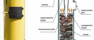
When lighting the stove during testing, it is necessary to inspect the chimney and lower container each time for the presence of water in them. If it is not there, then you can add oil (usually about 2-3 liters). Ignition must be carried out with a lit wick, which is inserted into the container through the hole. The oil usually reaches operating temperature in no longer than 5 minutes, but there are cases when the temperature is reached faster.
To speed up this process, you can add about 100 ml of kerosene to the used oil. The hole in the lower container should be left open literally a couple of centimeters, and later, by pushing the damper in or out, you can regulate the combustion process.
Receiving and draining device
The receiving and drainage device consists of a railway trestle with a drain tray, outlet trays, a tank service trestle and an intermediate tank (Fig. 5.15). A railway unloading platform for receiving railway tanks with fuel oil is constructed in the form of two longitudinal walls, between which a drain tray is installed. The walls are made of concrete blocks. Depending on the height of the overpass wall and the load-carrying capacity of the tanks, reinforced concrete belts are made along the bottom and top of the walls.
When supplying fuel oil in tanks with a lifting capacity of 50-60 tons, the trestle with a drain tray can be made of a lightweight design without installing a reinforced concrete bottom. A more advanced overpass has also been developed with a drain tray made of reinforced concrete I-beam elements 5.6 m long, weighing 12.5 tons each, representing the walls of the overpass (Fig. 5.16). The lower bars of the walls are connected by loop joints, which are monolid and form the bottom. The walls along the top in the longitudinal direction are connected by loop joints. To avoid freezing of the base, slag filling is carried out under the bottom of the tray. The fuel oil drain tray has a longitudinal slope of 0.01 towards the center of the overpass, from where the fuel oil is drained into an intermediate container. Outlet trays are made of structures similar to those of a railway overpass.
The receiving capacity of the main fuel oil facility must be designed for at least 15% of the capacity of tanks installed for unloading. Typically, the receiving tank consists of two underground tanks with a capacity of 600-1000 m 3 each. To service the tanks, a special overpass is constructed from prefabricated reinforced concrete elements.