An axonometric heating diagram is performed for a graphical representation of the intra-house piping of radiators of an individual heating system. This includes all structural components: thermal energy source, pipelines, pumps, mud traps, air vents, shut-off and control valves.
Such a graphic document must contain the main characteristics of all elements of the system. Without knowledge of heating engineering and drawing and drawing skills, it is quite difficult to perform an axonometry of the heating distribution, since it will be necessary to take into account many interrelated points, and in addition make thermal engineering calculations. For large multi-storey heating facilities, such schemes should be designed by highly specialized thermal power engineers.
Displaying communications in a drawing
When working with a project for internal water supply and sanitation, general drawings are prepared that combine water supply and sewerage.
In axonometric diagrams, these networks are always separated. Horizontal sections of networks are transferred horizontally to the projection. On the plan, risers are located near the group of devices being serviced and are indicated by large dots. In the diagram they are built vertically. The riser furthest from the input is shown in full. The remaining elements are performed partially, indicating their brand. Vertical drawing of risers allows you to display the valves installed on them. System parts displayed vertically on the design plan are drawn at an angle of 45°. According to the tracing, the cold water supply is laid 0.3 m above the floor, located with a slope of 0.002 towards the riser. This position is necessary for liquid drainage. The connection to the water fittings is made vertically.
All elements and components of the pipeline have their own markings and serial numbers on the drawing. Symbols show shut-off valves, taps, plumbing fixtures, and water meters. When making axonometry, the height standards for installation of water consumption points are applied:
- sink and sink faucet – 1.1 m;
- bathtub faucet – 0.8 m;
- connection to the water heating column - 0.8 m;
- connection to the flush tank - 0.65 m;
- fire hydrant – 1.35 m.
To shut off the flow of water in the event of an emergency and for preventive maintenance of the system, shut-off valves (taps, valves) are installed. They are located in key places:
- at the base of the risers (in a building of 3 floors or more);
- on entrances to apartments, connections to tanks, water heaters, showers;
- at the point of connection to the street network;
- on watering valves;
- at the water metering station.
Ground floor plan
This plan shows the risers of sanitary units located in the grooves of the main walls: water supply (StV1-1...StV1-3), sewer (StK1-1...StK1-3) and hot water supply (StV1-1...StV1-3). The diameters of these pipeline systems are also indicated.
Fragment of the ground floor plan
The designed pipeline networks, which are plotted on the plans, are the basis on which axonometric diagrams of plumbing systems are made. These diagrams provide a clearer picture of how the various elements of a building's piping systems are positioned in relation to each other.
Features of sketch design
Here attention is focused on the reflection of instruments. If one element climbs onto another, and this happens in most cases, then a dotted line is drawn indicating the displacement of the plumbing element for the purpose of a better visual effect
The axonometric diagram of the water supply system must include readings of all pipe diameters. If the toilet bowl is not marked on the outlet, then take a diameter of 50 mm; if there is one, the minimum diameter should be 100 mm
These numbers are important to remember. For risers, in 90% of cases, an indicator of 100 mm is used
Slopes in a similar diameter will be equal to 0.02; with an indicator of 50 mm, the slope angle is set to 0.03.
If you have already applied all the elements, mark the outlets whose diameter is larger than that of the risers; the slope is taken to be 0.02.
At the last stage of drawing up the axonometry, special notes are made based on the characteristics of the site and the construction plan. Here they note the level of soil freezing, the location of the foundation, as well as other factors that influence the corrections.
Designations
Each element of the heating system and circuit has its own marking.
- P – supply systems, system installations, exhaust systems;
- B – installation of systems;
- U - air curtains;
- A – heating units;
These were markings that related to a mechanically driven heating system.
For a heating system with forced impulse, other symbols on heating drawings are typical:
- St – heating system riser;
- GST – main riser of the heating system;
- GV – horizontal branch;
- K – compensator.
Heating drawings for a private house with such markings are presented in Figure 15.4.1. On the plan diagram, the installation of heating systems is depicted by points with diameters of 1-2 mm.
Sections of heating systems and their plans are carried out on the scales presented below:
For ventilation and heating installations:
- Layout diagram, plan – 1:400, 1:800;
- Sections and plans – 1:50, 1:100;
For ventilation and heating systems:
- Sections and plans – 1:100, 1:200;
- Fragments of sections and plans – 1:50, 1:100;
- Knots – 1:20, 1:50;
- Schemes – 1:100, 1:200;
The same data, but in a detailed type image - 1:2, 1:5, 1:10.
Maintenance of heating systems requires that the sections and plans of heating systems indicate such indicators as: the alignment axes of the building and the distance between them, marks of the main platforms and clean floors on the floors, sections of pipelines and air ducts, the number of radiator sections, the length and number of finned pipes type, and other details.
The naming of plans in a drawing such as an axonometric diagram of a heating system is done according to the type “Plan for the island.” If two or more plans are made at different levels, but within the same floor, then they must be named as follows: “Plan 2-2”, “Plan 3-3”.
If the pipelines are too long or the pipelines or air ducts have too complex an arrangement, then they will be shown on the diagram with breaks. An example of such a diagram is Figure 15.4.8.
An example of the design of heating system diagrams will be presented in Figure 15.4.8, and Figure 15.4.9 will show an example of a heating system installation diagram.
If the building is residential, then usually the heating concept is carried out only for its underground part. For a part of an above-ground building, a schematic diagram of the riser heating system and, if necessary, wiring in the attic of the building are issued.
Schematic diagram of heating
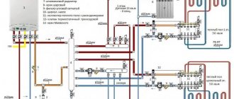
Figures 15.4.2 - 15.4.4 show the number of sections and diameter dimensions for calculating air temperature for buildings that have two floors or more.
Drawing of the heating section and ventilation system
A drawing of a private home heating system and heat supply installations usually depicts details such as:
- axonometry of the heating system components helps to manage the heating system and heat supply installations. This diagram is shown in Figure 15.4.10.
- You can specify one or another specification for the node diagram. The name of the control nodes may contain the node number. The components of the heating system diagrams and heat supply diagrams of installations are presented in Figure 15.4.11.
Diagrams of air conditioning and ventilation systems indicate the following information:
- Air ducts, their diameters, the amount of air that passes through them, and more;
- Hatches that are necessary to reveal the air parameters and the level of cleaning of the blowers. The diagrams also indicate the brands of hatches.
Also, the drawing of the heating system must include all the data that is needed during various works.
Drawing diagram of the air conditioning and ventilation system
If two heating systems are installed in the building at once, the number of the heating system will be indicated in the name of the scheme. Figures 15.4.14 and 15.4.15 show descriptions and examples of design of systems such as ventilation systems.
Drawing of the main ventilation units
The executive heating diagram and drawings, which indicate the rules for installing heating systems, represent not only installation plans, but also their sections. These cuts are made on the diagram in a simplified version, without unnecessary complicating details. Figure 15.4.17 shows a general diagram.
https://youtube.com/watch?v=Ef4t5uo2KAk
Hydraulic calculation of cold water supply
The hydraulic calculation of the cold water supply network begins after the constructive solution of the entire cold water supply system diagram, drawing an axonometric design diagram of the supply pipelines of the entire design building and quarter.
The purpose of the hydraulic calculation of internal cold water supply is to determine the estimated flow rates, pipe diameters and pressure losses in the calculated areas and throughout the system in such a way as to ensure uninterrupted water supply to all consumers in the building with the required pressure.
Hydraulic calculation is carried out in the following sequence:
A dictating point is selected taking into account the distance and height of the water fittings, as well as the amount of free pressure
for sanitary appliances.
The network is divided into design sections. Calculated
called the area where water flow is
permanent: pipeline sections between connection points of water fittings
to apartment wiring, apartment wiring to risers, risers to: highways. The breakdown into calculated sections is carried out against the direction of water movement, starting from the dictating point.
The number of devices served by the design area is determined. In this case, watering taps are not included in the calculation.
At each site the estimated water consumption is determined, l/s:
,
(4.4.1)
Where –
maximum second consumption of cold water, l/s, related to one device. Its value is determined by the device whose flow rate is the largest. Consumption per device
determined in accordance with clause 3.2.
a
is
a value determined depending on the total number of devices N in the design area and the probability of their action
P c .
Its value is determined from the table. 2 adj. 4 .
Probability of device action P c
for different sections of the network is determined immediately for the entire building as a whole (since the ratio
U N
= const).
(4.4.2)
where U –
number of residents in the house;
N –
number of all water fittings;
– rate of cold water consumption by one consumer per hour of greatest water consumption, l/h (Appendix 3).
(4.4.3)
– O
general rate of water consumption by the consumer at the hour of greatest water consumption, l/h (Appendix 3);
– rate of hot water consumption by one consumer per hour of greatest water consumption, l/h (Appendix 3).
Pipe diameters are selected from the table. for hydraulic calculation of water pipes based on calculated flow rates and permissible speeds. It should be borne in mind that the speed of water movement in the pipelines of internal water supply networks should not exceed 3 m/s. When selecting the internal diameters of cold water supply pipelines, you should focus on economical water speeds, which for pipes d 40 mm –
within 0.9...1.2 m/s.
Pressure loss, m, in sections of pipelines of cold water supply systems should be determined using the formula:
h =
i - l -( l + k l ),
(4.4.4)
where i –
specific pressure loss due to friction, mm/m;
/ –
length of the design section, m;
k–
coefficient taking into account pressure losses in local resistances.
In networks of utility and drinking water supply systems of residential buildings, k t =0.3 is assumed.
Along the main path from the dictating point to the city water supply, the amount of pressure loss is calculated.
It is convenient to perform hydraulic calculations in tabular form.
If there are risers on the axonometric diagram with different loads (number of devices), doubt may arise as to the correct choice of the dictating point. Therefore, to accurately find the dictating point, it is necessary to find the vanishing point (see Table 4.4.1.) of different risers (usually on the main line) and relative to it find the sum of pressure losses on one and the other branches, taking into account the difference in the geometric height of the installation of different devices (if dictating points adopted by different devices) and the required pressures necessary for their normal operation. Large losses determine the dictating riser and the location of the dictating point. Such a calculation is also necessary for drawing up a specification of materials and equipment for the entire house, since it is necessary to determine the diameters of all risers and sections of the main line. In this case, the table will look like:
(
);
Values are compared
And
. A riser is selected as the dictator, meaning
on which there is more.
Note:
It should be remembered that the section from the central heating point to the city water supply
(takeover) should be calculated at
And
.
List of requirements
The axonometric diagram of the ventilation system should include the following elements and symbols:
Figure 1. Table of symbols of devices for designing ventilation systems.
- All air ducts must have their specifications. To do this, draw an extension line with a shelf, on top of which indicate the diameter of the channel or its dimensions if it is of rectangular cross-section. At the bottom of the shelf they write the air flow rate in this duct, expressing it in m.
- The heights at which the air ducts will be laid must be indicated. If they are round in shape, then they indicate the mark of the channel axis, and if they are rectangular, they indicate its lower plane.
- Fans and additional equipment must be depicted with symbols or outlines. Some symbols of equipment that are most often found on diagrams are shown in Figure 1.
- If the ventilation scheme contains local hoods in the form of umbrellas, then the latter are depicted with symbols, and, if necessary, the contours of the equipment itself from which local suction is required are drawn.
- Local hoods (suction units) must be marked by making callouts and indicating the designations of the suction unit and its document. If local suction is included with the technological equipment, this need not be done.
- Hatches for measuring air speed in air ducts are shown in the places where they are installed, and a callout is made with a shelf, at the top of which the brand of the hatch is indicated, and at the bottom - the designation of its documentation.
- In the same way, additional equipment for adjusting and distributing air is marked by applying it using symbols.
- If some ventilation system ducts are subject to insulation or fireproof coating, this must be graphically indicated in these areas.
Table of device symbols for designing ventilation systems.
In complex and extended networks, air ducts cross building structures and floors. Load-bearing partitions on layouts are always marked with a digital or letter axis, and ceilings have their own finished floor marks. The axonometric diagram should display all this information, that is, the places where the channels intersect the floors should be conditionally shown on the diagram with the mark of this floor. The intersection of load-bearing partitions or external walls is depicted indicating the axis by which this structure is designated.
Ventilation systems must have their own designations, which consist of a letter and a number. The letter indicates the type of system - supply (P) or exhaust (V). The number that follows the letter indicates the serial number of the system. They are numbered according to their purpose, that is, serial numbers are assigned to the exhaust and supply networks separately. If the building has 3 exhaust and 2 supply systems, then their serial numbers will be B1, B2, B3, P1, P2. The fan involved in each of them is designated in the diagram, like the system itself - P1, B1.
What to pay attention to when creating a sketch
Before reflecting the axonometric diagram of heating a room in paper or electronic form, a number of calculations are carried out. The diagram itself is compiled based on the collected data:
- heat demand values for building rooms;
- typologies of heating devices, their quantities for each room;
- basic decisions regarding the entire engineering network: the use of risers, calculation of hydraulic branches and circuits, the order of connecting elements of the heating system;
- characteristics of pipeline sections: diameters and lengths of pipe fragments, shut-off valves, thermal controllers, hydraulic regulators.
Having received the appropriate calculations, their indicators are entered into the diagram. The axonometric diagram of the heating system necessarily contains the technical characteristics of each of the network nodes (boilers and pumps used), the length and diameter of the pipes, heat consumption and information about other thermal properties of heating devices, such as radiators, convectors, registers.
When starting to work on an axonometric drawing, first of all, the main ring of coolant movement is determined - the path to the most distant element from the boiler and back.
To summarize what has been studied, we will say that axonometry is mandatory, regardless of the type of communication system for structures of any type of purpose. Having a graphical drawing in front of their eyes, installers quickly determine how much work needs to be done and what exactly the network looks like.
If a specialist understands the axonometric heating diagram, and the drawing itself is executed correctly without any errors, then during the implementation of the project it is possible to eliminate the occurrence of any difficulties associated with the installation of elements of the heating system, pipelines and other utility networks.
In order for the design, and then the installation of the water supply system, to be successful, it is necessary to correctly visualize the building itself and the communication branches inside it on a sheet or in electronic form. In this case, the graphical component of the project includes:
- general plan of the building;
- situational diagram;
- facade;
- plans for each floor;
- roof plan;
- axonometric diagrams: ventilation, heating, water supply;
- sections and other schematic diagrams.
Remember that when working with correctly designed axonometry, problems with the installation of utility networks do not arise in 99.9% of cases. That is why this stage is so important in designing a future house or high-rise building.
Heating schemes for private houses vary. For example, single- or double-circuit, with natural or forced circulation of the coolant, but when the phrase “axonometric diagram of the heating system” is uttered, many people wonder what kind of diagram this is. To know what an axonometric heating diagram is, you need to understand what axonometry is in principle.
An example of an axonometric heating diagram
Treatment plants
Various devices can be used as treatment facilities:
- cesspool;
- septic tank;
- biological treatment station.
Each device has its own positive and negative qualities. A cesspool is better suited for small houses or cottages where people appear seasonally. Biological treatment stations are quite expensive, but demonstrate very good performance. A septic tank is an optimal design that can be made with your own hands or purchased ready-made.
Conclusion
There are different schemes of sewer networks. The selection of elements for the sewer system is a personal matter for each homeowner. It is enough to know the basic rules by which a sewerage system diagram is created and to carry out all the work correctly. The created structure will ensure the removal of wastewater from the building and provide a certain degree of living comfort in a private house.
How to reflect structural elements in electronic form
The fastest way to build a drawing is by cloning the entire diagram. To do this, select the “Insert” command, after which the integrated image is flipped. For the function to be executed, it is given a value equal to 45 degrees (the number is written in the program).
Having prepared the basis in the electronic version, where the risers are marked on the plan, they put symbols in the form of dots. To reflect all floors in the building, a vertical line is drawn. For the purpose of better perception, the diagram shows the floor panels.
Important! Don't make the slabs too long. Take advantage of the gap
A special feature of the axonometric sewerage diagram is the reflection of all elements of sanitary facilities: urinals, toilets, sinks, drains and other devices for carrying out hygienic procedures.
Design work
The general scheme of a sewerage system is an assembly of pipelines connected to plumbing on one side and to treatment facilities on the other. However, for the installation of a specific section of a drainage system, a detailed and accurate drawing is required. When calculating the project, it is necessary to ensure the requirements of SNiP, as well as sanitary standards for the placement of elements. Basic requirements for a drainage project:
- sufficient capacity with some reserve in case of extreme discharge of wastewater;
- correctly calculated configuration, maintained pipe slope;
- the route should be as straight as possible, without sharp turns;
- in the direction of flow of drains, pipes of smaller diameter should be connected to pipes of larger size, and not vice versa;
- the route must be equipped with the required number of inspection wells or inspection elements.
The scheme of the sewerage system is drawn up taking into account its size, purpose and specific use. The compiler’s task includes competent tracing, excluding sudden changes in the direction of the line. In addition, it is necessary to provide for the technologically correct arrangement of pipes and the appropriate position of the plumbing outlet elements. In the process of creating a project, an axonometric diagram of the sewerage system of a residential building is often used. It gives an idea of the spatial position of elements and pipelines. For complex structures with a multilayer structure, this version of the drawing is much more convenient and clearer.
Axonometry of water supply, heating, sewerage
According to GOST 2.317-2011, all axonometric diagrams related to sanitary systems of water supply, sewerage, and heating are constructed in frontal dimetric (oblique) isometry with a left coordinate system.
Accordingly, the dimensions along the z and x axes will be without distortion, and the dimensions along the y axis will be two times smaller.
You may ask, what does this drawing have to do with pipes and plumbing installation? Now imagine that the planes along the axonometric axes are the walls of your house or apartment. Plumbing pipes, water supply routes, sewerage and heating pipes run along the walls, vertically or horizontally. This means we can draw pipe routes in axonometry without showing the walls themselves.
This will give very clear drawings of how and where the plumbing wiring needs to be installed. Moreover, plumbing fixtures are marked on the axonometric diagram with symbols, pipe diameters are marked, explanations are made, and tables on materials and equipment are compiled for the diagrams. As a result, you have in your hands a detailed guide on how to install plumbing in a house (apartment), virtually eliminating installation errors.
Wikonanny rules
An example of the principle diagram for installing a ventilation system.
Ventilation schemes are usually drawn from the frontal isometric projection (axonometry). This design allows you to create the entire range of wind pipelines in three dimensions, so that, based on the plans or sections, the axonometric coordinate system contains a third of the whole, on which the height values are placed and. Current design programs provide the ability to clearly and quickly draw axonometric diagrams. Although it is not accessible to the skin, the result still needs to be seen on a paper nose. Therefore, such a diagram can be drawn in the hand from a sketch, a design, following a number of rules for drawing axonometric diagrams. By following them, you see a complete picture of the tide or exhaust system on the paper.
In accordance with the rules, it is necessary to choose the angle from which the façade will be, which is laid out on the plan below, the outer wall of which façade is designated by the first letter of the whole. If you are drawing a simple sketch of one location, then you can draw it out as carefully as possible, but remember that during the official preparation of documentation the chair will have to be reworked. The system's conductors should be applied according to the following principle:
- If the channel runs parallel to the façade specified for the design, it should be applied as a horizontal line;
- the wind duct perpendicular to this façade is drawn on the diagram at 45 degrees to the horizontal according to the same scale;
- vertical plots are marked with vertical lines.
Determination of axonometric heating diagram
Axonometry is one of the sections of applied drawing that studies, examines and provides the opportunity to obtain fairly accurate images of any objects in two or three projections. A rectangular axonometric projection is when the straight lines that project the image of an object are located perpendicular to the axonometric plane of projection. Rectangular projection includes isometric and dimetric. If the projection angle is not equal to 90°, then such a projection is called oblique axonometric. It also includes frontal dimetric and trimetric projections.
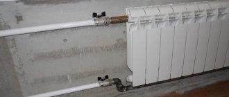
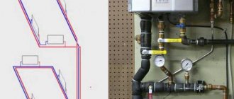
Manifold wiring in oblique axonometric projection
It follows that an axonometric heating diagram is any diagram of any heating of a multi- or low-story building, made in axonometry, and not in one plane. This helps to more clearly imagine the wiring and other elements of the heating system in real terms. With this approach to displaying heating elements, the projection of each object is performed as follows:
- The element is located on the diagram according to all three coordinate axes;
- The “picture plane” is defined – the element will be projected onto it. In this case, the “picture plane” should not run parallel to any of the coordinate axes;
- The projected node or element is completely transferred to the diagram.
Requirements for drawing up drawings of heating and other systems of a residential or industrial building are defined in GOST 21.602-2003. All heating elements and components according to GOST have their own designations: this is the marking and serial number included in the drawing. The following notations are used:
| Element or node | Marking |
| Heating riser | St |
| Main heating riser | Gst |
| Compensator | TO |
| Horizontal piping | GW |
| Thermometer | T |
| Pressure gauge | R |
Fragment of GOST 21.206-93 on designations of pipes and pipeline connections
According to GOST 21.206-93, pipeline systems are designated graphically. This applies to the following nodes:
- Common pipeline;
- Vertical riser directed downwards;
- Vertical riser directed upward;
- Flexible pipeline;
- Pipe crossing without connection;
- Simple connection of the pipeline or its elements;
- The connection of the pipeline or its elements is flanged;
- Coupling threaded connection;
- The coupling connection is quick-release;
- Socket connection.
The designations of shut-off valves, radiators and other elements are displayed in GOST 21.205-93. For example, such as:
- Wash basin;
- Foot bath;
- Toilet;
- Heating thermostat;
- Shower net;
- Air Dryer.
Fragment of GOST 21.205-93 on the designation of shut-off valves
Any axonometry cannot be displayed using standard means allowed in GOST, and for this there are additional requirements and permits. For example:
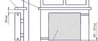
- Elevation and level marks can be moved outside the element or indicated directly on the contours of objects;
- An axonometric drawing of a heating circuit with bottom wiring or any other circuit can be made on a scale of 1:50, 1:100 or 1:200.
Technical organization of the air exchange system
There are different concepts and principles for arranging ventilation and airing systems. In the most optimized version, this will be a set of grilles with direct air exhaust channels that ensure the supply of street air. Standard home air circulation systems involve the organization of horizontal and vertical shafts. This infrastructure is carried out using metal or plastic air ducts of different sections. These can be rectangular and round, flexible and rigid structures, which are usually installed according to the principles of hidden installation.
List of equipment and parameters on the diagram
The heating diagram of any floor should indicate:
- Pipe distribution indicating all pipe diameters;
- Pipe insulation areas - length and thickness. Such thermal insulation is indicated graphically;
- Piping axes relative to zero level;
- Slope angles of bottlings;
- If there are gaps in the horizontal sections of the bottlings, then the dimensions of these sections are indicated;
- Supporting and hanging elements, compensators.
Mandatory requirement: it is necessary to indicate the type and main characteristics of these elements:
- How many sections does the heating radiator contain?
- How many sections or pipes are in the heating register, its diameter and total length;
- For other heating devices (convectors, radiators) – type of device;
- Designations of thermal installations (boilers, heating furnaces and heat exchangers, circulation and heat pumps, elevators, etc.);
- Mortgage equipment;
- Measuring instruments.
Heating diagram to scale
Heating equipment and calculations
All equipment used in the heating system is divided into auxiliary and main. The main one is a boiler or other heating device, the auxiliary one is radiators and distribution pipes with the accompanying fittings. To calculate the parameters of the required heating equipment, the specific power of the boiler is required, which varies depending on climatic zones:
- For regions of the Far North - 1.5-2.0 kW;
- For temperate climate zones and central regions - 1.2-1.5 kW;
- For southern zones - 0.7-0.9 kW.
Based on these amendments, the power of the heating device is calculated using the formula:
W boiler = S x W / 10;
Where W is the design power of the heating device (boiler, convector, etc.);
S – total area of the heated object.
Axonometric diagram of boiler equipment with two burners
Pumps are either heat or circulation pumps. In most cases, except for low-rise buildings with natural coolant circulation, it is impossible to do without pumping equipment, so these devices are present in almost all diagrams. Pumps must meet certain technical requirements, including the following:
- Ease of installation, dismantling, ease of operation and maintenance;
- Low noise and economical device;
- Reliability and durability.
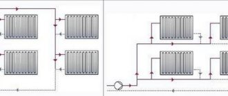
In low-rise residential buildings, three types of heating systems are used:
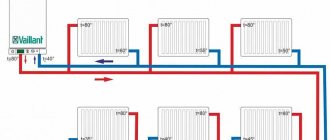
- The classic two-pipe scheme, according to which hot water is supplied through one pipe and returned through the second. In this scheme, the pump is mounted on the return line;
- Scheme with a vertical riser. In this scheme, hot water is also supplied to the radiators through one pipe and returned through the second, but a circulation pump is installed on the outlet pipe to supply hot coolant. Thus, hot water first passes through the upper radiators and then moves to the lower radiators of the system;
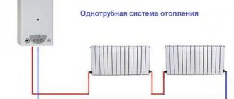
- The single-pipe scheme involves the movement of coolant sequentially from radiator to radiator with return to the boiler. This is the simplest scheme, but due to its low efficiency it is used in small one-story buildings.
Simplified axonometric two-pipe diagram
Calculations when drawing up a heating scheme should take into account:
- Heat consumption in each room;
- Type and number of radiators;
- The number of risers, if any, as well as the total number of branches and circuits;
- Connection diagram for heating devices;
- Parameters of pipes and shut-off valves.
After completing the calculations of the heating system, they must be indicated on the diagram. The main purpose of an axonometric heating diagram is a graphical display of all parts and elements, but, in addition, the diagram must also display the technical characteristics of the heating equipment. The diagram must also include calculations for the heat supply to each room of the house, including utility rooms.
Regulatory Requirements
They are comprehensively set out in GOST 21.602-2003, which regulates the rules for drawing up documentation for building engineering systems (including heating). Let us highlight from the text of the document the main points that are directly related to our topic.
General provisions
Elements of heating systems are assigned designations consisting of markings and a serial number within a given diagram. What designations are used?
| An object | Designation |
| Heating riser | St |
| Main heating riser (vertical filling part) | Gst |
| Compensator | TO |
| Horizontal branch (lezhnevka) | GW |
| Temperature measuring device (thermometer) | T |
| Pressure measuring device (pressure gauge) | R |
For some graphic symbols, the document refers to related GOSTs:
- Pipelines should be designated according to GOST 21.206 - 93.
- Designations of check valves, throttles, gate valves, radiators, etc. can be found in GOST 21.205-93.
Fragment of the designation table from GOST 21.205 – 93.
In addition, among the general provisions there are a number of additional requirements for drawings.
- Elevations are indicated on extension lines or element outlines.
- The axonometric heating diagram can be made on a scale of 1:50, 1:100 and 1:200.
List of designated equipment and parameters
The diagram drawn up by yourself should indicate:
- Pipelines with diameters indicated.
- Thermal insulation of pipeline sections. It is depicted graphically.
- Levels of the axes of all pipelines relative to the zero mark.
- Filling slopes (of course, where they are needed - in gravity systems and upper filling houses).
In the gravity system, filling slopes are indicated.
- If there are gaps in the horizontal sections of the bottlings, the sizes of the sections.
- Supports, compensators and suspensions.
- Shut-off valves. And in this case, a remote shelf is used, above which the type and diameter (DN) of the reinforcement is indicated. Below is the designation of the item according to the catalog.
- Risers and benches (horizontal sections) with symbols.
- Radiators, convectors and other heating devices.
Their type and main parameters must be indicated:
- Number of sections of a sectional radiator.
- The number of sections (pipes) of the register and its length.
- Number and length of finned tubes.
- For other heating devices - their type.
- Designations of installations (boilers, furnaces with heat exchangers, heat pumps, elevator units, circulation pumps for heating, etc.).
- Embedded devices (oil cups for temperature control and taps for installing control valves that allow pressure to be measured).
- The instruments themselves for measuring system parameters and heat metering.
Specifications
The standard sets out a number of requirements not only for the drawings themselves, but also for the specifications for them.
The elements listed in the specifications must be entered in them in the following sequence:
- Heating equipment (boilers, radiators, etc.).
- Shut-off and control valves (valves, gate valves, throttles, check valves).
- Other elements of heating systems (sump traps, discharges).
- Embedded structures (oil cups and bends for control valves).
The photo shows a real elevator unit in the basement of an apartment building. Anything that can be stolen is removed.
- Pipelines (bottlings, risers, connections).
- Thermal insulation.
Pipelines are entered into the specification for each diameter (usually by increasing diameter). Various bends, flanges, crosspieces for welding and bolts are not included in the specification.
An example of a specification for a drawing of a heating manifold.
What is manifold piping
With manifold heating distribution, heating pipes are supplied to heating radiators from a single distribution unit. The dispensing unit (manifold) is a device with one input and several coolant outlets. Each coolant (water) outlet is independently closed with a shut-off valve. That is, if necessary, you can separately turn off any radiator of the heating system, regardless of the others.
For heating distribution from the collector to the heating radiators, it is carried out using plumbing pipes suitable for heating systems. For heating the following are used:
- steel heating pipes,
- metal-plastic pipes,
- polyethylene and polypropylene pipes (hot water supply),
- copper pipes.
Heating pipes are connected by special devices called fittings. Heating pipes can have one or two types of connection. This is how metal-plastic pipes are connected using crimp fittings and press fittings. Polypropylene pipes are connected using welding fittings. Copper pipes are connected using press fittings and crimp fittings. Steel pipes are connected using a classic threaded connection using cast or brass fittings.
Installation algorithm
Installation of a two-pipe heating system, regardless of its characteristics, requires the use of the following tools, devices, materials and equipment
:
- tape measure, pencil/marker, building level, plumb line;
- electric drill;
- screwdriver;
- tool for pipeline installation (depending on the selected type of pipe);
- adjustable and gas wrenches;
- pipes (to choose from: metal-plastic, steel, copper, polypropylene);
- heating devices;
- air vents (manual for each battery, automatic for the entire circuit);
- expansion tank;
- boiler piping elements;
- drain valve and check valve for recharging the system, etc.
At the project preparation stage, it is necessary to perform a thermal calculation of the premises in order to determine the optimal power of heating devices. The type of radiators and pipes is also selected. Polypropylene is growing in popularity - such pipes do not corrode and do not overgrow, are suitable for hidden installation, are easy to install, and are affordable. The diameters of polypropylene pipes for a two-pipe system are determined depending on the thermal load and the length of the supply pipeline. The return line is mounted from pipes of the same section.
Features of drawings
When drawing up an axonometric diagram, pay attention to the following points:
- Plumbing and other fixtures connected to risers and the distribution network are reflected only when the necessary diagrams are not included in the attached documentation.
- The zero mark (first floor level) is shown on the risers by drawing a thin horizontal line. In the case of detailing the project, each of the nodes of the drawing is considered separately, reflecting it on an enlarged scale.
- If necessary, symbols of shut-off and control valves, watering taps and other system elements are added to sketches of diagrams and drawings of water supply networks and sewerage systems.
Compound
The diagram consists of a drawing and a table with symbols. The drawing must contain a sufficient amount of information to understand the operation of the ventilation system.
Legend
There are two types of schematic diagram - floor and cross section. The first one reflects the top view within one floor, the second one is an analogue of axonometry.
Each diagram necessarily includes symbols:
- Air ducts, connections between branches.
- Connection points for fans and air ducts.
- Air intake and supply points.
- Other equipment (recuperators, heaters).
All elements of the ventilation system contain callouts that briefly describe the model or name of the equipment.