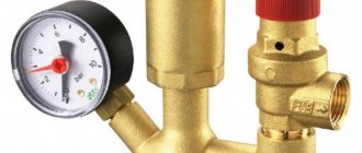
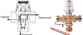
The bypass valve normalizes the pressure in the pipeline. The control valve redirects the energy carrier to an additional main circuit (bypass). The pressure of gas or liquid is maintained at the same level after automatic release of excess working fluid. The valve shutter opens when the pressure increases above the required value and closes when the pressure decreases.
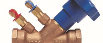
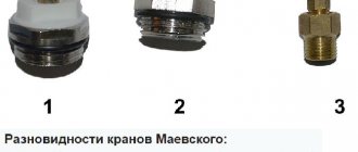
Bypass valve with fittings
Bypass valve and its role in the operation of the heating network
Heating systems and water heating devices experience constant changes in pressure and temperature during operation. Overheating or a sharp increase or decrease in the pressure of the working medium can cause breakdown of equipment or a pipeline unit and even a utility accident. To make the operating conditions of heating devices optimal and protect the heating network, devices are used that allow you to regulate the pressure of the coolant and maintain it at the required level - bypass valves.
What is the purpose of a bypass valve in a pipeline?
During operation of heating or water heating systems, the volume of the working medium may change. An increase or decrease in coolant pressure negatively affects the performance of the heating circuit: it can lead to uneven heating, airing of system components, and breakdowns. A change in the pressure of the working environment also affects comfort: the temperature in the rooms changes uncontrollably, and the pipes begin to hum and vibrate. To prevent this from happening, it is important to maintain a pressure balance in the pipeline.
It is not difficult to constantly monitor the pressure, bleed or add coolant manually, but it is better to entrust this routine work to automation.
There are several types of control valves that cope with this task better than a person.
The bypass, or overflow, valve allows you to stabilize the pressure in the pipeline by redirecting the working fluid through an additional branch of the pipeline, called a bypass.
Regulation does not occur by one-time or periodic bleeding of excess coolant, but in portions, due to which the pressure of the liquid or gas is constantly maintained at the same level.
Note! The bypass valve controls the pressure automatically, does not require human intervention and, unlike manual adjustment, does not air the system.
The device can and should be equipped with pipelines of any complexity, but most of all they need pressure adjustment:
- multi-circuit heating systems - if one of the circuits is turned off, coolant consumption decreases and pressure increases, which can cause pipeline breaks, overload the pump and heat-generating device - to avoid this, you need to reduce the pressure and maintain it at the required level;
- heating systems equipped with thermostats and hot water supply systems - when setting the temperature, the volume of coolant consumed changes, and it is necessary to quickly restore the pressure balance in the circuit;
- water supply systems equipped with storage-type water heaters - in the boiler and pipeline the water is under high pressure, and since the volume of supplied liquid changes jerkily due to constant adjustment and frequent turning on and off of water, it is especially important to regulate the pressure of the working medium so that an accident does not occur and The water heater is broken.
Product functions
The functions of such a device are to promptly discharge excess coolant volumes and thus reduce its pressure level. The general requirements for such nodes are that they must:
- help reduce pressure by promptly discharging excess coolants.
- have precise settings, and for heating systems in residential premises it is desirable that the settings be manual.
- have high strength and reliability.
- ensure the safe operation of heating systems thanks to the reliability of its own design.
Types of bypass valve designs
The bypass valve for heating systems can be of two types, characterized by operating principles. The most common is the spring version, but the lever-load version is mainly used in large highways. The principle of operation of the spring device is that during movement the coolant presses on a special valve, which is restrained by a spring.
When the pressure level is equal to the compression force of the spring, the safety rod opens and excess liquid begins to be discharged using the outlet pipe. After the situation returns to normal, the spring returns the valve to its original position, and the coolant continues to move without restrictions.
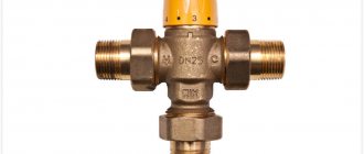
Heating system bypass valve
Spring devices are used in systems in which the pipe diameter does not exceed 200 millimeters; in other cases, a lever-load design is used. Its difference from the lever one, first of all, lies in the fact that in the absence of a spring, the rod is fixed using an additional weight, the weight of which can vary. In this case, the critical indicator is adjusted with a certain error, and the adjustment itself is performed by changing the weight of the load.
Operating principle
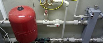
The bypass valve in the heating system is installed on the bypass - an additional pipeline line located after the pump or accelerating manifold and connecting the supply pipe to the return pipe.
If the boiler is part of a water heating system, then excess water can also be transferred in the opposite direction, but if the water heater is autonomous, the excess is discharged into the sewer.
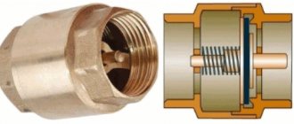
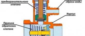
The design of the bypass valve is simple:
- inside the metal case there is a damper and a spring connected to it;
- an adjustment handle may be located on the outer part of the housing, allowing you to set the maximum pressure;
- Additionally, temperature and pressure sensors, a coolant make-up and discharge unit can be installed.
When there is excess pressure, the damper presses on the spring, opening the passage hole in the housing. Part of the flow from the coolant supply line is redirected to the outlet line. As a result, the pressure of the working medium is equalized to the required level and maintained in this state.
It is important! The greater the pressure of the liquid or gas in the pipes, the more the spring is compressed, the wider the housing opening opens and the more coolant is redirected to the additional circuit.
When the pressure of the coolant weakens, the spring expands and moves the damper back, closing the throughput hole and stopping the supply of the working medium to the additional circuit - the pressure in the pipeline is equalized.
What is it and why is it needed?
The volume of coolant changes during operation. A change in pressure impairs the performance of the heating main. The pipes heat up unevenly, air accumulates in certain areas, and components become unusable. The pressure balance is maintained manually, but it is better to entrust the change in the amount of fuel to automation, which requires a valve in the system.
Device specifications:
- DN is the nominal diameter of the connection pipes. The value is used in the case of standardization of standard sizes of collector fittings. Actual DN may vary slightly upward or downward. A similar characteristic was used in the post-Soviet period to indicate the diameter of the nominal bore - Dn.
- PN is the nominal pressure of liquid or gas at a temperature of +20°C. The pressure increase in the system remains within standard limits, ensuring operational safety. The characteristic was used in a similar designation Ru automation in the post-Soviet period.
- Kvs is the coefficient of ability to pass a volume of liquid when the coolant is heated to +20°C. The reduction in pressure in the automation shows 1 bar. The coefficient is used in calculations of hydraulic systems to identify pressure losses.
- Setting range is the difference in pressure change maintained by the automatic device. The indicator depends on the degree of elasticity of the spring.
Difference from other control devices
A bypass valve is often confused with a safety valve and a pressure relief valve. However, despite the general similarity in appearance and functions performed by these devices, there are differences in the mechanism of pressure reduction and the frequency of action.
| Device type | Pressure reduction mechanism | Frequency of action |
| bypass valve | excess working medium is diverted into an additional branch of the pipeline, the pressure of the liquid or gas passing through the main branch is regulated, while the valve is located on the additional | constantly as long as necessary |
| safety valve | excess coolant is released into the external environment or sewerage by opening the valve | occasionally due to pressure changes |
| pressure reducing valve (pressure reducer) | installed on the main branch and regulates the pressure of the working medium by decreasing and increasing its throughput, controls the pressure in the part of the pipeline located after the device | constantly |
Direct and indirect acting valve
Pressure control valves are divided into direct and indirect acting devices.
- The first type of valve has a simple design: a spring is driven by a shutter, which is directly pressed by the coolant. Such devices are inexpensive, easy to operate, reliable, insensitive to dirt, but not very accurate in settings.
- Indirect-acting devices, also called pulse devices, have a piston-actuated main valve, a smaller pulse valve, and a pressure transducer. When the pressure changes, the small valve presses on the piston, which moves the main valve, which regulates the throughput of the device. Thus, flow control occurs indirectly, in an indirect way. Valves of this type are less reliable due to the larger number of parts and are expensive, but they can be adjusted more accurately.
How to choose a valve for a boiler and bypass
In the factory configuration, boilers and bypasses are either equipped with the simplest bypass valve or do not have a device for redirecting the flow.
In the first case, you can not interfere with the design of the water heater or bypass element and install them in their existing form.
In the second case, it is necessary to purchase and install bypass valves. A bypass without this device will only allow the flow of the working medium to pass when the heating circuit is turned off, but will not be able to regulate the pressure. A boiler that is not equipped with a bypass valve is susceptible to overheating and may break down, since the water in it will boil and turn into steam, further increasing the pressure on the pipes and the heating unit itself.
The choice of device depends on the heating or water heating device: the fuel it uses, the maximum permissible pressure specified in the technical documentation.
Note! It is also important to consider your own capabilities to manage the pressure regulation process - whether you have the skills to configure the operating parameters of the bypass valve.
The price of the product in this matter can only play a role when choosing between similar devices from different manufacturers.
Different types of heating devices require valves of different designs:
- Systems running on electricity, gas or diesel fuel are undemanding - to regulate the pressure in them, a simple bypass valve that does not have additional elements is sufficient.
- Solid fuel does not stop burning immediately, therefore it is impossible to immediately turn off the solid fuel boiler or smoothly adjust the heating temperature. Therefore, in solid fuel heating systems it is important not only to regulate the pressure, but also to cool the heat-generating unit. Bypass valves are installed on bypasses and boilers, which respond to both an increase in pressure and an increase in the temperature of the coolant. Such devices are equipped with a temperature sensor, a coolant discharge and replenishment system and are connected to a sewerage system and a cold water supply system.
- A bypass valve with a control handle should only be installed if the homeowner already knows how to set the pressure limit. If you try to acquire this skill in practice, you can break the device, cause an accident, or get burned.
- For open-type thermal circuits, bypass valves are not required - the compensation tank copes with the task of regulating pressure without them.
- The technical characteristics of the bypass valve must correspond to the parameters of the heat source: the control valves must be set to the same maximum pressure as the heat-generating device and have a flow capacity no lower. It is also important to match the dimensions of the connecting pipes - if this condition is not met, you will have to use fittings for connection, which will make the system more vulnerable.
Specifications
Each bypass valve is characterized by several parameters, which should also be taken into account when choosing a product:
Source
Tips for choosing
Bypass valves correspond to the performance of heat generators, have the appropriate throughput and permissible pressure value. The pipes are connected without fittings; for this purpose, their diameter is selected so as not to increase the vulnerability of the pipeline.
Overflow valves are sometimes sold complete with a water heater or heating unit, or the device is purchased additionally and depends on the type of fuel and technical characteristics. The user’s ability to configure automation and set operating parameters is taken into account. Price plays a role only when choosing a model of devices of the same type with equal parameters, but differing in cost.
Purpose and areas of application
Bypass valves are installed in liquid and gas pipelines in which pressure may regularly increase for various reasons. The task of this device is to maintain operating pressure in the system. When the pressure increases in the section of the line in front of the installed valve, it releases part of the working medium into the bypass circuit, thereby reducing the pressure in the main system.
These devices are used in systems:
- cold and hot water supply,
- heat supply from any sources,
- cooling,
- conditioning.
A separate area is the automotive industry. They are installed in cooling and fuel supply systems. Bypass valves in turbocharged automobile engines regulate the air supply to the turbocharger.
Automotive engine turbine bypass valve
Causes and Effects
Often, an increase in the pressure level in such systems is associated with the normal functioning of thermal valves that are installed on radiators or a thermal head. When the maximum temperature set in manual mode is reached, the supply of hot coolant to one or another radiator is reduced, which ensures an increase in pressure, and in some cases even the whistle of the radiator shut-off valves.
Of course, this affects, in addition to the level of comfort in the room, also the performance and durability of the heating system and its individual components. To avoid such situations, professionals recommend equipping heating systems with thermostatic valves.
Design and principle of operation of any bypass valve
Its body is made of steel or brass. The main element of the internal mechanism is a shutter (flap) that closes the passage opening. The bolt is held closed by a spring. In some models, its role is played by a membrane or diaphragm. The spring force is regulated by an adjustment lever located on the outer surface of the housing.
Valve design diagram
The hydraulics of operation are based on the pressure of the working fluid flow in the pipeline on the valve located inside the housing. As long as the force is less than the lever set by adjustments, the drain hole remains closed. As soon as the pressure becomes greater than the setting pressure, the pressure on the spring leads to its compression. As a result, the drain hole becomes slightly open, and part of the flow is bypassed into the bypass circuit, reducing the pressure in the main hydraulic system.
Then the reverse process occurs - a decrease in pressure leads to the spring expanding and the valve closing, and the valve is again ready for the next reset. Pressure equalization occurs constantly, automatically. When the system operates in the “closed water valve” mode, the bypass channel remains constantly open, ensuring constant recirculation of the media flow through the bypass circuit.
Cross-section of the bypass device
Principle of operation
The coolant, water, and gaseous medium, moving through the pipeline, exert pressure on the valve, which is held in place by a spring. As soon as the pressure force reaches a predetermined level, the valve opens and the excess volume of the working medium is discharged through a special branch into another circuit of the system.
After the level drops to normal, the spiral returns the valve to its original position and the contents of the pipeline continue to circulate.
With a membrane mechanism, the passage for the coolant under the influence of pressure is opened by the membrane. When the pressure returns to normal, the membrane returns to its original place.
In a car, the turbine bypass assembly has a damper, the full opening or closing of which depends on the activator lever. The length of its pull can change over time under the influence of various factors. Therefore, this is monitored and the traction is adjusted.
Differences from other types of safety valves
Other valves installed for the safe operation of pipelines have a similar device and principle of operation. But they differ in purpose and requirements.
| Valve type | Mechanism of action | Principle of operation |
| Bypass | Installed in a bypass circuit and redirects part of the flow into it | Constantly working as needed |
| Safety | Reduces pressure in the system, throwing part of the media out | In case of emergency pressure increase |
| Reducing | By changing its throughput, it regulates the pressure in the part of the main circuit located after its installation site | Full time job |
The bypass valve reduces the load on the system pumps without changing the amount of media in it.
Where to mount and why
The thermostatic valve is mounted by inserting it into the system at a short distance from the liquid supply pump, between the return and supply circuit. The mode for setting the maximum permissible pressure limit of the working medium allows the owner to make the settings manually.
Currently, the range of these products offered by the retail chain is quite large.
But as practice shows, it is better to pay attention to such well-known brands as Mankenberg, Valtec, DANFOSS. They have proven in practice efficiency, reliability and durability in operation.
Purpose
Regulating thermostatic bypass valves are designed to ensure a stable pressure difference between the return and supply pipelines in closed heating systems. When the heat load decreases, the thermostatic radiator valves close. This leads to an increase in the pressure drop between the return and supply pipelines.
Using a bypass valve offers the following advantages:
- reduces the load on the pump;
- protects the boiler from rust;
- prevents the occurrence of noise unnatural for normal operation;
- increases the temperature of the working medium in the return pipeline.
By closing the thermostatic valves on the radiators, we will increase the resistance of our heating system (increase in the pressure difference between the return and supply pipelines). This will increase the load on the pump and lead to noise.
If the pressure reaches the maximum level, which corresponds to the settings of the bypass valve, it opens, forming an adjustable bypass. Also, a bypass valve is installed behind the circulation pump between the return and supply pipelines.
Specifications
The main quantities that determine the operation capabilities of bypass devices in the system:
- Passage diameter. Internal cross-section of the carrier passage through the valve. May differ from the diameter of the main circuit of the system.
- Bandwidth. Characterizes the volume of the working medium capable of passing through the valve per unit time at a nominal pressure of 1 atm. Measured in cubic meters/hour.
- Ultimate pressure. The maximum value of excess pressure for which the device is designed to operate. Exceeding this parameter in the system leads to displacement of the valve rod and the beginning of media bypass. Determined at a carrier temperature of 20 °C.
- Setting range. The limits of the possibility of adjusting the excess pressure at which the valve begins to open. The unit of measurement is bar.
Adjustment scale with tuning slider
Tips for setup and maintenance
Installing a valve with adjustment of the excess pressure range is worth it to those who already have experience in calculating the required value. The opening of the drain hole begins at the pressure selected by the setting. But it usually opens completely at a pressure exceeding the initial value by 20%. But the calculation cannot be based only on this indicator, because such a decrease in the operating pressure in the system is nonlinear. Relieving part of the carrier already leads to a reduction in the load on the valve shutter. Therefore, to accurately calculate the throughput of devices, they are guided by the diagrams given in the data sheet.
It should be taken into account that the setting error of most regulators is 10%. For initial adjustment and subsequent monitoring, it is recommended to install pressure gauges before and after the bypass point.
The adjustment itself is carried out either by moving the slider along the scale or by rotating the adjusting screw. After setting and checking the required value, the screw is secured with a clamping nut.
Routine maintenance of the bypass valve consists of monthly monitoring of the initial response pressure and its opening speed. You also need to monitor the condition of the filters.
If the valve does not operate correctly, it should be dismantled, disassembled and all parts washed. Perhaps the malfunction is caused by a simple clogging of the mechanism.
Types of bypass valves
Although the operating principle and performance characteristics are similar, the devices have additional differences.
Connection method
On small diameter pipelines (up to 150 mm), the inlet and outlet pipes are usually made with a threaded connection. Options - external or internal thread of the pipe. For large cross-section pipelines, connections are made by welding or using flange connections.
Large Diameter Flanged Valves
Flow direction
The valve installed in the main flow usually has an angular shape for connecting the outlet circuit. Valves included in the bypass line can also be direct-flow.
Direct Flow Bypass Valve
Active element
Typically, the outlet is blocked by a shutter or damper. But in some designs, the locking element is a diaphragm connected to a rod. The use of diaphragm options is recommended in pipelines with a working medium containing solid particles in addition to liquid or gas.
Mechanism of action
The difference in the method of influencing the shut-off element led to the emergence of two types of valves.
- Direct action. A simple mechanical device in which the coolant directly acts on the active element of the valve. Inexpensive and relatively easy to maintain.
- With elements of indirect influence. It actually consists of two valves. The small diameter valve works as a pressure sensor and, when activated, controls the main valve rod, which opens the drain into the bypass channel. Characterized by more precise adjustment of the response threshold.
Mechanism
The design includes a metal body (cast iron, bronze, brass), inside of which there is a damper and a spring that activates it. The valve can be a spool valve, a plate, etc. Another option is a shut-off membrane with a rod. A handle is built into the body, which is used to adjust the device.
Devices used in large networks and large-diameter pipelines may contain a lever-load mechanism in their housing.
Bypass valve design:
Device selection criteria
Bypass valves are required in the following types of pipelines:
- Boiler storage systems. The water in them is under pressure, and periodic switching on/off leads to sudden changes in the volume and pressure of the flowing liquid.
- Continuous hot water supply systems equipped with temperature control devices. When the temperature changes, the volume of the medium in the line also changes. Constant adjustment and smoothing of pressure differences is required.
- Multi-circuit heating systems. When any of the circuits is turned off, the pressure in the remaining parts increases. Bypass devices minimize load changes on the system pumps.
- Solid fuel heating devices are not capable of sharply reducing the temperature of the medium after shutdown. Bypassing the flow line, the cooling time can be reduced.
When selecting a suitable bypass type safety device, the following parameters must be taken into account:
- Diameter and connection method allowing it to be included in a regulated line.
- The throughput must correspond to the calculated media outlet in case of maximum load.
- Operating temperature of the device and material of its manufacture.
- The need to adjust the valve actuation point. Its range should be within the planned pressure changes.
Focusing on products from a well-known manufacturer is also important.
Selection tips and approximate prices
When choosing a bypass device, the consumer must be aware that it is designed to ensure normal operation of the system and constantly maintain stable pressure inside it.
Such a device must meet the following requirements:
- help reduce pressure, quickly redirect excess coolant volume to another circuit;
- have a sufficient range of adjustment;
- be suitable for the method of connection to pipes, for example, have a threaded connection for pipes with a diameter of ½′′.
The throughput device is selected, first of all, based on the type of working medium of the pipeline: gas, steam, water.
Next, they are guided by certain criteria.
Criteria
The main ones are:
- features of the actuator;
- pipeline type and configuration;
- valve material;
- device diameter (DN), which should not be less than the cross-section of the supply pipe;
- range of pressure drops supported by the device;
- damper capacity, characterized by maximum and minimum Kvs values;
- operating and maximum media temperature.
The specific operating pressure to which the valve must be adjusted is specified in the data sheet.
It is important to provide for correct installation, for which everything must be correctly calculated taking into account the parameters and configuration of the system. For example, in a complex heating structure, it is better to install an overflow regulator behind all pumps, and additionally use check valves to protect them
The approximate price for bypass valves for domestic use varies from 1,700 to 5,200 rubles. Industrial designs equipped with measuring instruments, flanges, and a wide range of settings are much more expensive.
Thus, the overflow angle valve shown in the photo with DN ¾”, designed for 0.06-0.36 bar, with an adjusting head, will cost 1,680 rubles. It is installed to ensure normal operation of the pump. Drains excess coolant when the pressure in the radiators is exceeded into the return line.
If you have to purchase a bypass device for a car, you must take into account all the features of the previous one, and do not chase after cheap fakes.
Installation features
The specific installation location of the bypass device depends on the layout and type of pipeline. The valve can be integrated into an additional diverter circuit. For closed-cycle heating systems, excess pressure is released into the return pipeline. It can also be used as a safety valve, adjusted to emergency pressure and with liquid discharge into the sewer system.
In a single-circuit heating main circuit, the bypass valve is installed in the bypass outlet after the injection pump.
Bypass valve for local heating system. Installation diagram.
For greater safety and security of the entire heating circuit, it is advisable to install additional ones in addition to the bypass device:
- check valve to prevent reverse flow direction,
- air vent valve for bleeding air pockets,
- drain valve to completely drain the media from the system,
- for small-diameter cottage-type systems - mesh filters.
In multi-circuit systems, bypass valves are installed in each circuit.
Pumping and mixing unit VALTEC COMBIMIX. Ideology of basic regulations
- Technical support
- Articles
- Pumping and mixing unit VALTEC COMBIMIX. Ideology of basic regulations
#warm floor #built-in heating #design #installation #adjustment
The VALTEC COMBIMIX (VT.COMBI) pump and mixing unit is designed to maintain a given temperature of the coolant in the secondary circuit (due to mixing from the return line). Using this unit, it is also possible to hydraulically link an existing high-temperature heating system and a low-temperature underfloor heating circuit. In addition to the main control elements, the unit also includes the entire necessary set of service elements: an air vent and a drain valve, which simplify the maintenance of the system as a whole. Thermometers make it easy to monitor the operation of the unit without the use of additional devices and tools.
It is permissible to connect an unlimited number of heated floor branches with a total power of no more than 20 kW to the VALTEC COMBIMIX node. When connecting several branches of a heated floor to a node, it is recommended to use VALTEC VTc.594 or VTc.596 collector blocks.
The main adjustment elements of the pumping and mixing unit:
1. Secondary circuit balancing valve (position 2
on the diagram).
This valve ensures mixing of the coolant from the return collector of the heated floor with the coolant from the supply pipeline in the proportion necessary to maintain the specified temperature of the coolant at the outlet of the COMBIMIX unit.
The valve setting is changed using a hex wrench; to prevent accidental rotation during operation, the valve is secured with a clamping screw. Kvτ capacity values
valve from 0 to 5 m3/h.
Note: Although the valve capacity is measured in m3/h, it is not the actual coolant flow rate passing through this valve.
2. Balancing shut-off valve of the primary circuit (pos. 8
)
Using this valve, the required amount of coolant is adjusted that will flow from the primary circuit to the unit (unit balancing). In addition, the valve can be used as a shut-off valve to completely shut off the flow. The valve has an adjusting screw with which you can set the valve capacity. The valve is opened and closed using a hex key. The valve has a protective hex cap.
3. Bypass valve (pos. 7
)
During operation of the heating system, a mode may arise when all control valves of the heated floor are closed. In this case, the pump will operate in a muted system (without coolant flow) and will quickly fail. In order to avoid such modes, there is a bypass valve on the unit, which, when the valves of the underfloor heating system are completely closed, opens an additional bypass and allows the pump to circulate water through a small circuit in idle mode without loss of functionality.
The valve is activated by the pressure difference created by the pump. The pressure difference at which the valve opens is set by turning the regulator. There is a scale on the side of the valve with a range of 0.2–0.6 bar. Pumps recommended for use with COMBIMIX have a maximum pressure of 0.22 to 0.6 bar.
After the heating system is completely assembled, pressure tested and filled with water, it should be adjusted. The adjustment of the control unit is carried out together with the commissioning of the entire heating system. It is best to adjust the unit before starting to balance the system.
Algorithm for setting up the control unit:
1. Remove the thermal head (1
) or servo drive.
To ensure that the control valve actuator does not affect the assembly during adjustment, it must be removed.
2.
Set the bypass valve to the maximum position (0.6 bar).
If the bypass valve is triggered while the unit is being configured, the setup will be incorrect. Therefore, it should be set to a position in which it will not work.
3.
Adjust the position of the secondary circuit balancing valve (item
2 in the diagram).
The required capacity of the balancing valve can be calculated independently using a simple formula:
t 1
–
coolant temperature on the supply pipeline of the primary circuit;
t 11
–
temperature of the coolant on the supply pipeline of the secondary circuit;
t 12
–
coolant temperature in the return pipeline (both circuits are the same);
Kvτ
is
the control valve capacity coefficient; for COMBIMIX it is assumed to be 0.9.
Obtained Kv
set on the valve.
Calculation example
Initial data: design temperature of the supply coolant
– 90 °C; design parameters of the heated floor circuit are 45 – 35 °C.
Kv value is set on the valve.
4.
Set the pump to the required speed.
To do this, you need to calculate the water flow in the secondary circuit and the pressure loss in the circuits after the unit using the formulas:
G2 = 3600 Q
/
s
(
t
11 –
t
12), kg/h;
ΔP _
n= Δ
P
s + 1, m aq. Art.,
where Q
– the sum of the thermal power of all loops connected to COMBIMIX;
c
– heat capacity of the coolant (for water – 4.2 kJ/kg °C; if a different coolant is used, the value should be taken from the data sheet of this liquid);
t
11,
t
12 – temperature of the coolant on the supply and return pipelines of the circuit after the COMBIMIX unit.
Δ P
с – pressure loss in the design circuit of the heated floor (including collectors). This value can be obtained by performing a hydraulic calculation of the heated floor. To do this, you can use the calculation program VALTEC.PRG.
Using the pump nomograms presented below, we determine the pump speed. To determine the pump speed, a point with the corresponding pressure and flow rate is marked on the characteristic. Next, the nearest curve above this point is determined, and it will correspond to the required speed.
Example
Initial conditions: underfloor heating with a total power of 10 kW, pressure loss in the most loaded loop of 15 kPa (1.53 m of water column).
Water flow in the secondary circuit:
G 2
= 3600 · Q / s · ( t 11 – t 12 ) = 3600 · 10 / 4.2 · (45 – 35) = 857 kg/h (0.86 m3/h).
Pressure losses in the circuits after the
COMBIMIX with a reserve of 1 m of water.
Art.: Δ P n = Δ P s
+ 1 = 1.53 + 1 = 2.53 m water.
Art. The selected pump speed is
MED at the point (0.86 m3/h; 4.05 m water column):
If it is not possible to calculate the pump, then this step can be skipped and immediately proceed to the next one. At the same time, set the pump to the minimum position. If during the balancing process it turns out that there is not enough pump pressure, you need to switch the pump to a higher speed.
5.
Balancing the branches of the heated floor.
Close the balancing shut-off valve of the primary circuit. To do this, open the valve cover and use a hex wrench to turn the valve counterclockwise until it stops.
The task of balancing heated floor branches comes down to creating the required coolant flow in each branch and, as a result, uniform heating.
The branches are balanced with each other using balancing valves or flow regulators (not included in the COMBIMIX kit; flow regulators are included in the VTc.596.EMNX manifold block). If there is only one circuit after COMBIMIX, then nothing needs to be linked.
The balancing process is as follows: balancing valves/flow regulators on all branches of the heated floor are opened to the maximum, then a branch is selected in which the deviation of the actual flow from the design one is maximum. The valve on this branch closes to the required flow rate. Thus, it is necessary to adjust all the branches of the heated floor.
When adjusting the VT.FLC15.0.0 flow regulators, you simply need to set the desired flow rate on the scale in l/min by turning the knob. If it is not possible to use a flow indicator, then you can balance the branches approximately by heating the floors or by the temperature of the return coolant.
If during the balancing process it was not possible to obtain the required flow rate through the branches even with the valves open, this means that the hydraulic calculation was performed incorrectly and the pump should be switched to a higher speed.
Setting the primary circuit balancing valve
The balancing valve of the primary circuit is adjusted together with the balancing of the rest of the heating system. The essence of balancing a heating system is to adjust the coolant flow through each heating device, including COMBIMIX, exactly according to the design. If heating systems are not balanced correctly, the system may operate when some of the heating devices are overheated and some are not warmed up enough.
Consider the following diagram of a heating system with a connected COMBIMIX node. This is a two-pipe dead-end heating system with horizontal wiring.
Below the diagram is a piezometric graph. The graph shows the pressure drop in the heating system with green slanted lines. The device located closest to the boiler (or individual heating point) has a greater pressure drop between the forward and return pipelines (vertical lines) than the device located at the end of the system. The orange color on the vertical lines shows the pressure drop across the devices without taking into account the balancing valves, the green color shows the pressure drop that must be created across the valve in order to balance the system. The higher the pressure drop across the device, the greater the flow rate passes through it at the same throughput. In order to equalize the coolant flow in the system, it is necessary to add resistance to devices that are closer to the boiler using balancing valves or control valves. The closer the device is to the boiler, the more resistance must be added using the valve (more valve closing). The graph shows that the valve of the first device is closed so much that its resistance is several times higher than the resistance of the radiator. With the latter device, the valve is practically open and its resistance is low.
Balancing, as a rule, comes down to finding the desired setting of the balancing valves. There are three main ways to perform balancing.
The calculation method consists in the fact that when hydraulically calculating a heating system, a similar piezometric graph is drawn up for the designed heating system. During the hydraulic calculation, the required pressure loss at each balancing valve is determined. Next, the following formula determines the valve capacity:
k v = V
/√Δ
P,
m3/h,
where V
– volumetric coolant flow rate, m3/h;
Δ P
– required pressure loss across the valve, bar.
After calculating the capacity according to the recommendations of the balancing valve manufacturers, the adjuster sets the design capacity value on each valve. Hydraulic calculations must be carried out by a qualified specialist manually or using specialized programs, for example the VALTEC.PRG engineering systems calculation program.
Example
First, let's determine the required coolant flow in the primary circuit. To do this, you can use the following formula:
G 2
= 3600 · Q / s · ( t 1 – t 2 ),
where Q is the sum of the thermal power of all devices connected after COMBIMIX; c – heat capacity of the coolant (for water – 4.2 kJ/kg °C; if a different coolant is used, the value should be taken from the data sheet of this liquid); t1, t2 – temperature of the coolant in the supply and return pipelines of the primary circuit (the temperatures of the coolant in the return pipeline of the primary and secondary pipelines are the same).
For a heated floor with a total power of 10 kW with a design temperature of the supply coolant of 90 °C, design parameters of the heated floor circuit of 45–35 °C, the coolant flow in the primary circuit will be as follows:
G 2
= 3600 · Q / s · ( t 1 – t 2 ) = 3600 · 10 / 4.2 · (90 – 35) = 155.8 kg/h.
When calculating, the designer determined that the pressure loss on the balancing valve of the unit should be 9 kPa (0.09 bar), in order for the coolant flow in the primary circuit to be 0.159 m3/h, the kv of the valve should be:
kv= 0.159 /√0.09 = 0.53 m3/h.
Next, according to the characteristics of the balancing valve of the primary circuit given below, the number of turns of the adjusting screw is determined.
To determine the number of revolutions, you can not count kv but use the nomogram given below. To do this, plot the required flow through the primary circuit and the required pressure loss across the valve on the graph. The nearest inclined line will correspond to the required setting (number of revolutions). To improve accuracy, you can interpolate the obtained values.
The first line of the table indicates the position, the second line of the table indicates the number of turns of the adjusting screw. (In this example, 2 and ¼.) The third line shows Kv for this setting, as you can see it practically coincides with the calculated one.
Setting the valve speed:
The correct adjustment of the valve should start from the position of the valve being fully closed; using a thin flat-head screwdriver, tighten the adjusting screw until it stops and put a mark on the valve and on the screwdriver.
Using the valve setting table, turn the screw the required number of revolutions. To fix the speed, use the marks on the valve and screwdriver. (following the example, you need to make 2 and ¼ turns).
Using a hex key, open the valve until it stops. The valve will open exactly as much as you turn the screwdriver. After setting the valve, you can open and close it using a hex wrench, while maintaining the capacity setting.
In the same way, all other balancing valves of the heating system are calculated. The number of valve revolutions (or the setting position is determined according to the methods of balancing valve manufacturers).
Second balancing method
system is that the settings of all valves are set “in place”. In this case, the setting values are determined based on the actually measured coolant flow rates for individual branches or systems.
This method is used, as a rule, when setting up large or critical heating systems. During balancing, special devices are used - flow meters, with which you can measure flow in individual directions without opening the pipeline. Balancing valves with fittings and special pressure gauges are also often used to measure the pressure drop, which can also be used to determine the flow rate in individual areas. The disadvantage of this method is that instruments designed to measure flow are too expensive for one-time or infrequent use. For small systems, the cost of the devices may exceed the cost of the heating system itself.
When balancing using this method, COMBIMIX is configured as follows:
Fix the flow meter on the pipeline through which COMBIMIX is connected to the heating system. Calibrate and configure the flow meter according to the instructions for the flow meter.
Then smoothly open the balancing valve using a hex wrench, while recording the change in coolant flow. As soon as the coolant flow corresponds to the design, fix the position of the valve using the adjusting screw.
Example
As for the previous example, the coolant flow rate is first calculated.
For a heated floor with a total power of 10 kW, a design temperature of the supply coolant of 90 °C, and design parameters of the heated floor circuit of 45–35 °C, the coolant flow in the primary circuit will be as follows:
G2 = 3600 · Q /c · (t1 – t2) = 3600 · 10 / 4.2 · (90 – 35) = 155.8 kg/h (0.159 m3/h).
Close the balancing valve completely using the hexagon:
Smoothly open the valve using a hexagon and record the flow rate on the flow meter until the flow rate reaches the design value (in the example, 0.159 m3/h).
After the coolant flow has been established, fix the position of the shut-off valve using the adjusting screw (tighten the adjusting screw clockwise until it stops).
After the adjusting screw is fixed, the valve can be opened and closed using a hexagon, the setting will not be lost.
For small systems
In the absence of a project and complex measuring instruments, the following balancing method is acceptable:
In the finished system, turn on the boiler and central pump (or other heat supply source), then close all balancing valves on all heating devices or branches. After this, the heating device that is installed furthest from the boiler (heat supply source) is determined. The balancing valve in this device opens completely; after the device has completely warmed up, it is necessary to measure the temperature difference of the coolant before and after the device. Conventionally, we can assume that the temperature of the coolant is equal to the temperature of the pipeline. Then we move on to the next heating device and smoothly open the balancing valve until the temperature difference between the forward and return pipelines coincides with the first device. Repeat this operation with all heating devices. When the turn comes to the COMBIMIX unit, its adjustment should be carried out as follows: If the coolant temperature in the supply pipeline is equal to the design one, then the balancing valve of the primary circuit should be smoothly opened until the readings on the thermometers of the supply and return pipelines of the secondary circuit are equal to the design ± 5 °C.
If the temperature of the coolant in the supply pipeline during setup of the system differs from the design one, then the following formula can be used for recalculation:
where temperatures with index "P" –
design, and temperatures with the index “H”
are
adjustment (used for adjustment) values.
Example
Consider the following heating system:
To begin with, all balancing valves are closed.
The heating device that is furthest from the boiler is selected. In this case, it is the rightmost radiator. The radiator balancing valve opens completely. After the radiator has warmed up, the temperature of the forward and return pipelines is recorded.
For example, after opening the valve, the temperature in the supply pipeline was 70 °C, the temperature in the return pipeline was 55 °C.
Then a second device is taken at a distance from the boiler. The balancing valve on this device opens until the temperature in the return pipeline is equal to the temperature of the first ±5 °C.
COMBIMIX setting: design temperature of the supply coolant – 90 °C; design parameters of the heated floor circuit are 45–35 °C. Actual readings taken from thermometers: supply coolant temperature – 70 °C.
Using the formula, we determine the temperature of the coolant in the supply pipeline of the secondary circuit:
We determine the temperature of the coolant in the return pipeline of the secondary circuit:
We open the balancing valve of the secondary circuit until the temperatures on the
COMBIMIX coincide with the calculated ones
± 5 ° C.
Fix the position of the shut-off valve using the adjusting screw (tighten the adjusting screw clockwise until it stops).
After the adjusting screw is fixed, the valve can be opened and closed using a hexagon, the setting will not be lost.
Next, configure all remaining balancing valves in the same way.
Bypass Valve Setting
There are two ways to set the bypass valve:
- If the resistance of the most loaded branch of the heated floor is known, then this value should be set on the bypass valve.
2. If the pressure loss on the most loaded branch is unknown, then the bypass valve setting can be determined from the pump characteristics.
The valve pressure value is set to 5–10% less than the maximum pump pressure at the selected speed. The maximum pump pressure is determined by the pump characteristics.
The bypass valve should open when the pump approaches a critical point, when there is no water flow and the pump works only to build up pressure. The pressure in this mode can be determined from the characteristic.
An example of determining the setting value of a bypass valve.
In this example, it can be seen that the pump, in the absence of water movement at first speed, has a pressure of 3.05 m of water.
Art. (0.3 bar), point 1
;
at average speed - 4.5 m water. Art. (0.44 bar), point 2
;
and at a maximum of 5.5 m water. Art. (0.54 bar), point 3
.
Since the pump is set to medium speed, we select the setting on the bypass valve 0.44 - 5% = 0.42 bar.
6.
Final stage
After setting up all the components of the COMBIMIX unit, you should put the thermal head of the control valve back on and make sure that the control valve is working. Close the cover of the primary circuit balancing valve. The unit is ready for use.
Setting up heating systems is one of the most difficult engineering tasks. The VALTEC COMBIMIX pump and mixing unit allows you to simplify this task. This unit is a ready-made comprehensive solution for organizing a heated floor circuit in heating systems. A well-thought-out configuration of the unit allows you to eliminate errors when designing a particular system. The flexibility of the unit setup allows you to set up underfloor heating systems without the use of special devices.
Print the article: Pumping and mixing unit VALTEC COMBIMIX. Ideology of basic regulations
“twist
© Copyright holder Vesta Regions LLC, 2010 All copyrights reserved. When copying an article, a link to the copyright holder and/or to the website www.valtec.ru is required.