Heating systems and water heating devices experience constant changes in pressure and temperature during operation. Overheating or a sharp increase or decrease in the pressure of the working medium can cause breakdown of equipment or a pipeline unit and even a utility accident. To make the operating conditions of heating devices optimal and protect the heating network, devices are used that allow you to regulate the pressure of the coolant and maintain it at the required level - bypass valves.
What is a bypass for heating systems?
This is the name of a section of pipe installed in such a way as to open an additional path for coolant circulation. A bypass in a heating system can direct water bypassing a certain section of the main line or parallel to the pipe. The bypass section can be equipped with equipment, one end connected to the inlet pipe, the other to the outlet pipe.
The bypass valve is supplemented with shut-off valves to shut off the coolant supply through the bypass passage and regulate the flow of water to radiators and pipeline branches. To make it easy to disconnect part of the system, a battery or a certain area from the flow of coolant, a ball valve is installed on the outlet pipe. Installation area - the area between the bypass valve and the outlet hole on the heating boiler, central riser or other device.
When using a bypass device:
- in the process of piping radiators when installing single-pipe circuits;
- when pumping equipment is installed in an autonomous heating system;
- at the installation point of the mixing unit, when the heated floor contour is formed;
- in the process of arranging a small coolant flow circuit when piping a solid fuel boiler.
Why do you need a bypass in the heating system of a private house and residential complexes?
In a two-pipe system, a bypass is necessary to direct the heating source to other radiators. Using a jumper, you can regulate the microclimate of a private home, leaving the necessary heat in the required rooms.
Using a bypass you can control the microclimate of a private home
Nuances:
- When the electric pump is turned off, heating will stop.
- Bypass can save a difficult situation.
- By turning off the pump tap and running the coolant through the jumper, you can activate natural circulation without stopping the heating system.
If an emergency leak occurs in the radiator, you simply need to turn off the taps on the jumper. Water will bypass the system and it will be possible to dismantle the circuit element and replace it without complications. Weather conditions often bring surprises. In autumn and spring, the pipeline supplies excessive amounts of heat. In this case, you can shut off the unit, stopping the access of hot water to the radiators, regulating the comfortable conditions in the room.
How to choose a valve for a boiler and bypass
In the factory configuration, boilers and bypasses are either equipped with the simplest bypass valve or do not have a device for redirecting the flow.
In the first case, you can not interfere with the design of the water heater or bypass element and install them in their existing form.
In the second case, it is necessary to purchase and install bypass valves. A bypass without this device will only allow the flow of the working medium to pass when the heating circuit is turned off, but will not be able to regulate the pressure. A boiler that is not equipped with a bypass valve is susceptible to overheating and may break down, since the water in it will boil and turn into steam, further increasing the pressure on the pipes and the heating unit itself.
The choice of device depends on the heating or water heating device: the fuel it uses, the maximum permissible pressure specified in the technical documentation.
The price of the product in this matter can only play a role when choosing between similar devices from different manufacturers.
We recommend that you read: Which heating is better and how to install it in a private house
Different types of heating devices require valves of different designs:
Systems running on electricity, gas or diesel fuel are undemanding - to regulate the pressure in them, a simple bypass valve that does not have additional elements is sufficient. Solid fuel does not stop burning immediately, therefore it is impossible to immediately turn off the solid fuel boiler or smoothly adjust the heating temperature
Therefore, in solid fuel heating systems it is important not only to regulate the pressure, but also to cool the heat-generating unit. Bypass valves are installed on bypasses and boilers, which respond to both an increase in pressure and an increase in the temperature of the coolant. Such devices are equipped with a temperature sensor, a coolant discharge and replenishment system and are connected to a sewerage system and a cold water supply system.
A bypass valve with a control handle should only be installed if the homeowner already knows how to set the pressure limit. If you try to acquire this skill in practice, you can break the device, cause an accident, or get burned. For open-type thermal circuits, bypass valves are not required - the compensation tank copes with the task of regulating pressure without them. The technical characteristics of the bypass valve must correspond to the parameters of the heat source: the control valves must be set to the same maximum pressure as the heat-generating device and have a flow capacity no lower. It is also important that the dimensions of the connecting pipes match - if this condition is not met, you will have to use fittings for the connection, which will make the system more vulnerable
Such devices are equipped with a temperature sensor, a coolant discharge and replenishment system and are connected to a sewerage system and a cold water supply system. A bypass valve with a control handle should only be installed if the homeowner already knows how to set the pressure limit. If you try to acquire this skill in practice, you can break the device, cause an accident, or get burned. For open-type thermal circuits, bypass valves are not required - the compensation tank copes with the task of regulating pressure without them. The technical characteristics of the bypass valve must correspond to the parameters of the heat source: the control valves must be set to the same maximum pressure as the heat-generating device and have a throughput not lower
It is also important that the dimensions of the connecting pipes match - if this condition is not met, you will have to use fittings for connection, which will make the system more vulnerable
Specifications
Each bypass valve is characterized by several parameters, which should also be taken into account when choosing a product:
| Characteristic name | What does it mean |
| throughput | volume of coolant consumed per unit time at unit pressure |
| nominal pressure | maximum excess pressure of the working environment, maintained at 200 degrees |
| nominal diameter | the internal cross-section of the connecting pipes may have a slight deviation from the actual size |
| setting range | limits of the maximum pressure adjustable on the valve |
Selection tips and approximate prices
When choosing a bypass device, the consumer must be aware that it is designed to ensure normal operation of the system and constantly maintain stable pressure inside it.
Such a device must meet the following requirements:
- help reduce pressure, quickly redirect excess coolant volume to another circuit;
- have a sufficient range of adjustment;
- be suitable for the method of connection to pipes, for example, have a threaded connection for pipes with a diameter of ½′′.
The throughput device is selected, first of all, based on the type of working medium of the pipeline: gas, steam, water.
Next, they are guided by certain criteria.
Criteria
The main ones are:
- features of the actuator;
- pipeline type and configuration;
- valve material;
- device diameter (DN), which should not be less than the cross-section of the supply pipe;
- range of pressure drops supported by the device;
- damper capacity, characterized by maximum and minimum Kvs values;
- operating and maximum media temperature.
The specific operating pressure to which the valve must be adjusted is specified in the data sheet.
It is important to provide for correct installation, for which everything must be correctly calculated taking into account the parameters and configuration of the system. For example, in a complex heating structure, it is better to install an overflow regulator behind all pumps, and additionally use check valves to protect them.
You should pay attention to the reliability of suppliers so as not to run into counterfeit products.
The approximate price for bypass valves for domestic use varies from 1,700 to 5,200 rubles. Industrial designs equipped with measuring instruments, flanges, and a wide range of settings are much more expensive.
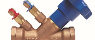
Thus, the overflow angle valve shown in the photo with DN ¾”, designed for 0.06-0.36 bar, with an adjusting head, will cost 1,680 rubles. It is installed to ensure normal operation of the pump. Drains excess coolant when the pressure in the radiators is exceeded into the return line.
If you have to purchase a bypass device for a car, you must take into account all the features of the previous one, and do not chase after cheap fakes.
Bypass installation
Knowing how the bypass works in a heating system and why it is needed, you can move on to specific examples. Most often it can be found in single-pipe schemes of multi-storey buildings. But besides this, it is widely used in autonomous systems of private houses. For proper installation, it is necessary to calculate the heating bypass and select components for it.
Bypass in the radiator trim
Bypass in the heating radiator
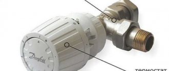
The organization of a bypass channel in the radiator piping is done not only in one-pipe, but also in two-pipe schemes. With its help, you can regulate the flow of coolant and perform repair and maintenance work without stopping the boiler or disconnecting from the central heating.
How to make a bypass to the heating system yourself? First, you should make preliminary calculations and select the right components. It is recommended to use pipes made of the same material as for the entire line. The difference will only be in the cross section. Without fail, the diameter of the bypass in the heating system must be 1 size smaller than the cross-section of the main pipe.
Before installing it yourself, please read the following recommendations:
Ball valves must be installed as shut-off (shut-off) valves. With their help, you can quickly redirect the coolant to the bypass; Installation of a mixing valve is not rational. It effectively mixes cold and hot water in collector systems, where the coolant flow rate is initially normalized. For pipelines, and even more so for central heating, this is impossible to achieve; Arrangement of a bypass in a one-pipe heating system is mandatory
It is important to pre-coordinate the installation with the management company.
Bypass installation diagram
To install a parallel pipeline, consumables are purchased. Let's consider, using the example of a metal-plastic highway, the optimal set of components. Why is a bypass needed in the heating system in this case? It will act as a bypass circuit to repair or replace the radiator, as well as to regulate the flow of water into the battery section. First, the distance between the forward and return radiator pipes is measured. Before making a bypass into the heating system, the pipe is cut to the dimensions obtained. The most common pipe size in autonomous heating is ½. Based on this, components will be selected, the characteristics and costs of which are presented in the table.
| Name | price, rub. | Qty | Sum |
| Metal-plastic pipe, m.p. | 23 | 0.5 m | 12 |
| Tee | 75 | 2 pcs. | 150 |
| Male thread adapter | 50 | 2 pcs. | 100 |
| Control valve | 448 | 1 PC. | 448 |
| Ball valve | 137 | 2 pcs. | 274 |
| Total | 984 |
Before the bypass in the heating system starts working, you should check the reliability of all connections. To do this, pressure testing of this section of the pipeline is performed, preferably hydraulically. Only after this can the pipes be filled with coolant.
Bypass for installing a circulation pump
Types of heating pump units
Unlike radiator piping, the purpose of a bypass in a forced-type heating system is to minimize hydraulic losses. To do this, the pump is not installed on the return pipe, but directly on the bypass.
What is a bypass in the heating system in this case? It performs the same functions as when piping the radiator. A distinctive feature is the installation of a check valve on the pipe. It is necessary to prevent a change in the direction of coolant flow when the pump is turned off.
In addition, during installation you need to take into account the following features:
- A bypass is required in an autonomous heating system with forced circulation. Without it, when there is a power outage, the speed of movement of the coolant will sharply decrease;
- The optimal diameter of the bypass in the heating system for piping the pump is 2 sizes smaller than the cross-section of the main pipe;
- A strainer is installed in front of the pump to prevent debris from entering its mechanism.
Air and its release from the heating system
Air congestion is a fairly common occurrence, but an unpleasant one. Characteristics that indicate that there is air in the radiator and bleeding is required:
- presence of noise during operation;
- corrosion.
Pressure plays an important role in any system. There are a number of reasons that can affect pressure changes. One of the most common reasons for an increase in pressure is the formation of an air lock.
Air may appear in the system and require bleeding due to several factors:
- the presence of dissolved air in the water, which, when heated, accumulates in the upper part of the pipe;
- accidental air release during installation;
- when filling the system with water, they did not adhere to certain rules: slowly filling the pipes with coolant;
- air could be sucked in through poor sealing at the joints of the structure.
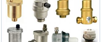
The heating system air bleed valve is an important and mandatory element in every design. The best way to eliminate air is a multi-stage deaeration system. Air drain elements are installed not in one place, but in several. If started correctly, the air bleeding stage will not be difficult.
The air bleed element is:
- manual;
- auto.
The presence of several drain valves does not imply their simultaneous opening. If this is a multi-story building, then all the air will accumulate in one place and, due to pressure, go to the neighbor. When the bleeder valve opens, a hissing sound is heard, which means that air is escaping from the radiator.
The drain valve must not be opened completely and one at a time
It is important to carry out the air descent slowly, gradually. After a hissing sound, water will begin to drip from the drain valve.
It is important to continue and open the drain element until the water does not drip, but flows in a trickle. This means that the air has escaped.
How is the heating system automatic make-up valve used?
Since the main coolant in heating systems is water, during operation the liquid gradually loses its volume, that is, its quantity decreases.
When coolant volumes reach a critical value, the balance of the heating system is disrupted.
The operation of the heating system becomes more controlled and balanced if an automatic replenishment valve for the heating system is installed. After all, constantly using the valve to normalize the pressure in the heating system is too labor-intensive, and the user simply forgets about such types of adjustment, so it would be preferable to install an automatic make-up valve.
- The pressure in the circuits is constantly monitored,
- The coolant enters the system in portions, without placing additional load on the heat exchanger,
- No air leaks into the system.
More on this topic on our website:
- I choose floor heating radiators - water with a fan
- The floor design of heating equipment has its own subtleties, as well as a number of negative and positive aspects, which you should learn about in more detail.
Inverter for heating boiler - which one to choose, pros and cons
- Electrical energy is actively used during the operation of the heating system; it is thanks to it that the coolant receives the required temperature and distributes it through the pipelines. Developments aimed at significantly increasing productivity.
Safety valve in the heating system - why and how to install it
- Due to constant changes in coolant temperature in heating circuits, an involuntary increase in the volume of water in the system occurs, and a special valve will provide reliable protection against this phenomenon. Let's try.
How to choose an electric boiler for heating your home
- Definitely, starting with simple words, we can say something like this - an electric boiler is extremely necessary today. The reason, which is also an explanation, is very simple and lies in.
Principle of operation
The coolant, water, and gaseous medium, moving through the pipeline, exert pressure on the valve, which is held in place by a spring. As soon as the pressure force reaches a predetermined level, the valve opens and the excess volume of the working medium is discharged through a special branch into another circuit of the system.
After the level drops to normal, the spiral returns the valve to its original position and the contents of the pipeline continue to circulate.
With a membrane mechanism, the passage for the coolant under the influence of pressure is opened by the membrane. When the pressure returns to normal, the membrane returns to its original place.
In a car, the turbine bypass assembly has a damper, the full opening or closing of which depends on the activator lever. The length of its pull can change over time under the influence of various factors. Therefore, this is monitored and the traction is adjusted.
Installation steps for a bypass valve (for radiators and with a circulation pump)
Installing a bypass valve with your own hands
Installing a bypass in a heating system equipped with a circular pump is done as follows:
- excess liquid is drained from the common pipe;
- a section of pipe measuring 40 cm is removed from the coolant;
- holes of the required diameter are cut at the ends of the pipe to connect the bypass;
- a filter is installed on the cut areas;
- then the bypass valve is installed;
- the hydraulic pump crashes.
Installation of a bypass in a heating system
For heating batteries, the following installation scheme applies:
- the diameters of the bypass and main pipes are checked;
- the following are mounted at the connecting ends: single-pipe jumpers and an adjustment valve;
- Next, the valve is installed at the closest possible distance from the heating radiator.
Necessary tool
You can install the bypass line yourself using installation tools, the list of which consists of the following items:
- tape measures for measuring the length and volume of a pipe;
- level for adjusting heating devices and water supply slope;
- pliers for removing and maintaining individual parts of the heating system;
- adjustable wrenches for joining the structure;
- a set of keys for installation (regular);
- metal cutter;
- screwdrivers: Phillips and flathead;
- pipe cutter (for large diameter pipes);
- welding machine;
- a grinding machine for leveling the corners of pipes and pipes;
- hammer drill;
- gas burner.
For a one-time job, it is not necessary to purchase all the tools, but you can rent them.
Recommendations and common mistakes
The insertion of the bypass valve should be done according to the rules of SNIP and the recommendations below:
- Before installation, it is advisable to install filters (mesh type).
- Installing monomers will help control water pressure.
- Do not twist, compress or stretch the pipes during installation.
- The average size of pipe joints should not exceed 5 DN before and 10 DN after the bypass.
The bypass valve can be mounted on horizontally and vertically directed sections of pipes, in accordance with the installation instructions.
Types and designs
According to the operating principles, bypass valves are distinguished with spring and membrane designs. Spring mechanisms prevail in systems where the pipeline cross-section is no more than 200 mm; in other water supply and heating networks, the lever-load principle is used.
Membrane units are increasingly used when working with liquid media that contain solid particles.
Depending on the pipeline environment, bypass devices are intended for:
- gas;
- pair;
- liquids.
According to the purpose of the system, they are used for pipelines:
- cold water supply,
- hot water supply,
- heating,
- cooling,
- conditioning.
In heating and water supply systems, bypass valves are distinguished according to their purpose:
- for radiators;
- for boiler and bypass;
- for automatic replenishment;
- for low or high pressures.
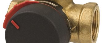
This photo shows an overflow valve with a setting scale. Made of bronze and brass, designed for installation in central heating systems.
Along with bypass regulators, the following is installed in the heating design:
- air vent to prevent air locks in pipes;
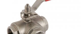
- three-way valve for mixing or separating hot and cold water flows;
- reverse, preventing backflow in the pipeline.
For industrial and utility networks, designs with a nominal diameter DN of up to 500 mm and a flange connection are used.
In the car there are access devices for:
- turbines;
- fuel supply mechanism;
- engine cooling systems.
The turbine bypass unit discharges the exhaust gases, reducing the pressure force in the manifold. Thus, it protects the engine from overheating.
Mechanism
The design includes a metal body (cast iron, bronze, brass), inside of which there is a damper and a spring that activates it. The valve can be a spool valve, a plate, etc. Another option is a shut-off membrane with a rod. A handle is built into the body, which is used to adjust the device.
Devices used in large networks and large-diameter pipelines may contain a lever-load mechanism in their housing.
Bypass valve design:
How is the heating system automatic make-up valve used?
Since the main coolant in heating systems is water, during operation the liquid gradually loses its volume, that is, its quantity decreases.
When coolant volumes reach a critical value, the balance of the heating system is disrupted.
To prevent such deviations in the operation of heating circuits, a special valve is used that normalizes the operating pressure and ensures stability.
The operation of the heating system becomes more controlled and balanced if an automatic replenishment valve for the heating system is installed. After all, constantly using the valve to normalize the pressure in the heating system is too labor-intensive, and the user simply forgets about such types of adjustment, so it would be preferable to install an automatic make-up valve.
In addition, when using a valve, there is a real risk of increasing differentiated pressure, which will lead to an emergency and damage the heating equipment. And another negative phenomenon when using a manual increase in coolant supply is air bubbles that leak into the heating system.
- The pressure in the circuits is constantly monitored,
- The coolant enters the system in portions, without placing additional load on the heat exchanger,
- No air leaks into the system.
The heating system design must include not only heating equipment, but also additional elements that can ensure uninterrupted and stable operation.
How does a heating meter work?
Bypass in the heating system
Device selection criteria
Bypass valves are required in the following types of pipelines:
- Boiler storage systems. The water in them is under pressure, and periodic switching on/off leads to sudden changes in the volume and pressure of the flowing liquid.
- Continuous hot water supply systems equipped with temperature control devices. When the temperature changes, the volume of the medium in the line also changes. Constant adjustment and smoothing of pressure differences is required.
- Multi-circuit heating systems. When any of the circuits is turned off, the pressure in the remaining parts increases. Bypass devices minimize load changes on the system pumps.
- Solid fuel heating devices are not capable of sharply reducing the temperature of the medium after shutdown. Bypassing the flow line, the cooling time can be reduced.
When selecting a suitable bypass type safety device, the following parameters must be taken into account:
- Diameter and connection method allowing it to be included in a regulated line.
- The throughput must correspond to the calculated media outlet in case of maximum load.
- Operating temperature of the device and material of its manufacture.
- The need to adjust the valve actuation point. Its range should be within the planned pressure changes.
Focusing on products from a well-known manufacturer is also important.
Installation features
The specific installation location of the bypass device depends on the layout and type of pipeline. The valve can be integrated into an additional diverter circuit. For closed-cycle heating systems, excess pressure is released into the return pipeline. It can also be used as a safety valve, adjusted to emergency pressure and with liquid discharge into the sewer system.
In a single-circuit heating main circuit, the bypass valve is installed in the bypass outlet after the injection pump.
Bypass valve for local heating system. Installation diagram.
For greater safety and security of the entire heating circuit, it is advisable to install additional ones in addition to the bypass device:
- check valve to prevent reverse flow direction,
- air vent valve for bleeding air pockets,
- drain valve to completely drain the media from the system,
- for small-diameter cottage-type systems - mesh filters.
In multi-circuit systems, bypass valves are installed in each circuit.
Operating principle
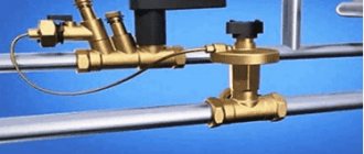
The bypass valve in the heating system is installed on the bypass - an additional pipeline line located after the pump or accelerating manifold and connecting the supply pipe to the return pipe.
If the boiler is part of a water heating system, then excess water can also be transferred in the opposite direction, but if the water heater is autonomous, the excess is discharged into the sewer.
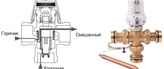
The design of the bypass valve is simple:
- inside the metal case there is a damper and a spring connected to it;
- an adjustment handle may be located on the outer part of the housing, allowing you to set the maximum pressure;
- Additionally, temperature and pressure sensors, a coolant make-up and discharge unit can be installed.
When there is excess pressure, the damper presses on the spring, opening the passage hole in the housing. Part of the flow from the coolant supply line is redirected to the outlet line. As a result, the pressure of the working medium is equalized to the required level and maintained in this state.
It is important! The greater the pressure of the liquid or gas in the pipes, the more the spring is compressed, the wider the housing opening opens and the more coolant is redirected to the additional circuit.
When the pressure of the coolant weakens, the spring expands and moves the damper back, closing the throughput hole and stopping the supply of the working medium to the additional circuit - the pressure in the pipeline is equalized.
Differences from other types of safety valves
Other valves installed for the safe operation of pipelines have a similar device and principle of operation. But they differ in purpose and requirements.
| Valve type | Mechanism of action | Principle of operation |
| Bypass | Installed in a bypass circuit and redirects part of the flow into it | Constantly working as needed |
| Safety | Reduces pressure in the system, throwing part of the media out | In case of emergency pressure increase |
| Reducing | By changing its throughput, it regulates the pressure in the part of the main circuit located after its installation site | Full time job |
The bypass valve reduces the load on the system pumps without changing the amount of media in it.
What is it and why is it needed?
A bypass valve, also known as an overflow valve, is a device that regulates the pressure in the system by bypassing or draining an excess volume of the working medium (gaseous or liquid) into another circuit. The peculiarity of the unit is that it is capable of doing this continuously, which differs from its safety analogue, which reduces the pressure in the pipeline by one-time or periodically removing the medium from it.
A similar pressure reducer, in contrast to the overflow unit, maintains a stable pressure of liquid in the flow following from it, while the overflow unit maintains a stable pressure before itself.
For systems with solid fuel boiler
When used in combination with solid fuel heating equipment, the bypass allows the formation of a small circulation circuit. To do this, the bypass pipe is installed in the supply, where there is a coolant heated to the limit, and is connected to a three-way valve located on the opposite side of the structure.
Thanks to the valve, hot water from the bypass and cold water coming from the return circuit are mixed. As a result, a coolant whose temperature exceeds 50 degrees is returned to the boiler for the subsequent heating cycle.
Fuel pump hp-Technik UHE series with bypass valve and bypass
Fuel pump hp-Technik UHE series - with bypass valve and bypass.
Fuel pumps are used in oil burners and pumping stations to create the pressure necessary for equipment operation and pump fuel.
Areas of application for hp-Technik fuel pumps:
Combustion systems
Boiler burners, closed circulation pipelines, pumping all types of liquid boiler and marine fuels EL, L, M, S, ES, coal tar and coal oil, tar, kerosene, etc.
Mechanical engineering
Hydraulic pumps for control units of hydraulic systems, lubrication pumps for pumping lubricating oils and greases, pumps for water cooling systems for supplying oil-water emulsion.
Oil industry Feed (pressure) pumps for oils, mineral lubricants, tar, resins, tar, bitumen, etc.
Shipbuilding Lube oil pumps and booster pumps for supplying marine lubricants, diesel fuel, fuel oil and heavy viscous oils.
Advantages of hp-Technik fuel pumps:
Self-priming, self-lubricating, vibration-free, silent, maintenance-free, with hermetically sealed shaft.
Instructions for the fuel pump hp-Technik UHE series
| Direction of shaft rotation: I – Reverse direction (counterclockwise). | ||||||||||||||
| UHE series pump models | Working fluid viscosity, cSt: 6.0 at 20 °C | Gear rotor, F | Val,F | Threaded connection for (S/A/R) | Pressure meter connection (M1/M2) | Max. shaft rotation speed, rpm | Weight, kg | |||||||
| Flow, l/h at 1400 rpm | Flow, l/h at 2800 rpm | |||||||||||||
| Art. No. I | 9 bar | 30 bar | 40 bar | Art. No. I | 9 bar | 30 bar | 40 bar | |||||||
| UHE-A2-PZ | 05110542 | 200 | 155 | 140 | 05130542 | 500 | 380 | 330 | 38 | 12 | G 1/2″ | G 1/4″ | 3500 | 4,4 |
| UHE-A3-P | 05110543 | 300 | 260 | 240 | 05130543 | 700 | 600 | 550 | 38 | 12 | G 1/2″ | G 1/4″ | 3500 | 4,6 |
| UHE-A4-M | 05110544 | 450 | 425 | 390 | 05130544 | 900 | 850 | 800 | 38 | 12 | G 1/2″ | G 1/4″ | 3500 | 4,8 |
| UHE-A5-GZ | 05110545 | 550 | 500 | 450 | 05130545 | 1300 | 1150 | 1050 | 38 | 12 | G 1/2″ | G 1/4″ | 3500 | 5,0 |
| Shaft rotation direction: D – Direct direction (clockwise). | ||||||||||||||
| UHE series pump models | Working fluid viscosity, cSt: 6.0 at 20 °C | Gear rotor, F | Val,F | Threaded connection for (S/A/R) | Pressure meter connection (M1/M2) | Thermal power H1, W at 220 V, 50 Hz | Torque, M (Nm) | |||||||
| Flow, l/h at 1400 rpm | Flow, l/h at 2800 rpm | |||||||||||||
| Art. No. D | 9 bar | 30 bar | 40 bar | Art. No. D | 9 bar | 30 bar | 40 bar | |||||||
| UHE-A2-PZ | 05120542 | 200 | 155 | 140 | 05140542 | 500 | 380 | 330 | 38 | 12 | G 1/2″ | G 1/4″ | 110 | 1,6 |
| UHE-A3-P | 05120543 | 300 | 260 | 240 | 05140543 | 700 | 600 | 550 | 38 | 12 | G 1/2″ | G 1/4″ | 110 | 1,6 |
| UHE-A4-M | 05120544 | 450 | 425 | 390 | 05140544 | 900 | 850 | 800 | 38 | 12 | G 1/2″ | G 1/4″ | 110 | 1,6 |
| UHE-A5-GZ | 05120545 | 550 | 500 | 450 | 05140545 | 1300 | 1150 | 1050 | 38 | 12 | G 1/2″ | G 1/4″ | 110 | 1,6 |
