Heaters have high performance, so with their help you can heat even very large rooms in a fairly short time. Many models of these devices operating on the basis of different coolants go on sale.
To choose the best option, you need to calculate the heater, which can be done either manually or using an online calculator. We will help you figure out the issue of calculations - in this article we will give an example of the calculations that will be needed when choosing a suitable device for heating air.
We will also consider the design features of various types of air heaters, the advantages and disadvantages of a heating system using such devices.
Calculation of heater power
The calculation of the heater power depends on the required performance and the planned temperatures at the inlet and outlet of the ventilation system. For example, for Moscow the average temperature difference in winter is 44°C (from -26°C to 18°C). The table below shows the gradation of the heater power according to its performance for heating the passing air by 44°C.
| Heater power | Performance |
| 1.2 kW | 80 m³/h |
| 2.4 kW | 160 m³/h |
| 3.6 kW | 240 m³/h |
| 4.8 kW | 330 m³/h |
| 7.5 kW | 510 m³/h |
| 10.8 kW | 730 m³/h |
| 15.0 kW | 1020 m³/h |
| 22.5 kW | 1520 m³/h |
| 30.0 kW | 2030 m³/h |
As can be seen from the table, the calculation of the power of air heaters depends on the volume of air passing through it.
Mixing unit
You can control the operation of the heater in two ways:
- quantitative - by adjusting the volume of coolant at a constant temperature
- high-quality - regulating the temperature of the coolant, but maintaining a constant flow
The qualitative method is considered safer in terms of the risk of heater freezing. Ready-made mixing units are expensive and designed for large flows. I was interested in making the mixing unit myself. The main source of information was the forums forum.abok.ru/. The masters at my.mastergrad.com acted as serious critics.
Final scheme:
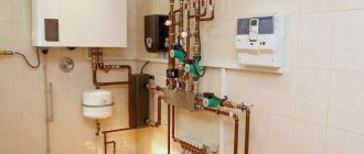
- three-way valve 1 is connected as a mixing element; it is installed so that output C (which always has a supply) faces the heater 3 . The remaining two inputs are connected to the external circuit 9 and the internal circuit 10 through a check valve 11 . Valve 12 allows the valve to be operated in two-way mode.
- circulation pump 2 is installed in a small circuit on the return line. To minimize the impact on the heating network, the weakest Grundfos COMFORT 15-14 was chosen. There were doubts about the performance, but in the end, it was able to provide the 0.1 - 0.2 m3/hour required by the heater.
- to balance the internal circuit, I added a bypass 4 with a check valve 5 and valve 6
- in order not to stop the external circuit, I added a bypass 7 with valve 8
- shut-off valves installed at both ends 13
- to control the flow through the heater, I installed a regular water meter
The photo shows the final result:
- The second photo shows the moment of operation at an outside temperature of -25 °C. In this case, the three-way valve is open approximately halfway, the supply water temperature is +75 °C, the return water temperature is +50 °C.
Selecting an air handling unit
To select an air handling unit, we will need the values of three parameters: overall performance, heater power and air network resistance. We have already calculated the performance and power of the heater. The network resistance can be found using the Calculator or, for manual calculation, taken equal to the typical value (see section).
To select a suitable model, we need to select ventilation units whose maximum performance is slightly greater than the calculated value. After this, using the ventilation characteristic, we determine the system performance at a given network resistance. If the obtained value is slightly higher than the required performance of the ventilation system, then the selected model is suitable for us.
As an example, let’s check whether a ventilation unit with the ventilation characteristics shown in the figure is suitable for a cottage with an area of 200 m².
The estimated productivity is 450 m³/h. Let us take the network resistance to be 120 Pa. To determine the actual performance, we must draw a horizontal line from the value of 120 Pa, and then draw a vertical line down from the point of its intersection with the graph. The intersection point of this line with the “Performance” axis will give us the desired value - about 480 m³/h, which is slightly more than the calculated value. So this model suits us.
Note that many modern fans have flat ventilation characteristics. This means that possible errors in determining the network resistance have almost no effect on the actual performance of the ventilation system. If in our example we had made a mistake in determining the resistance of the air supply network by 50 Pa (that is, the actual network resistance would not have been 120, but 180 Pa), the system performance would have dropped by only 20 m³/h to 460 m³/h, which had no effect would be the result of our choice.
After choosing an air handling unit (or a fan, if a dial system is used), it may turn out that its actual performance is noticeably higher than the calculated one, and the previous model of the air handling unit is not suitable because its performance is not enough. In this case we have several options:
- Leave everything as is, but the actual ventilation performance will be higher than the calculated one. This will lead to increased energy consumption spent on heating the air during the cold season.
- “Strangle” the ventilation unit using balancing throttle valves, closing them until the air flow in each room drops to the calculated level. This will also lead to excessive energy consumption (although not as much as in the first option), since the fan will work with excess load, overcoming the increased network resistance.
- Do not turn on maximum speed. This will help if the ventilation unit has 5–8 fan speeds (or smooth speed control). However, most budget ventilation units have only 3-step speed control, which most likely will not allow you to accurately select the desired performance.
- Reduce the maximum productivity of the air handling unit exactly to a specified level. This is possible if the automatic ventilation unit allows you to adjust the maximum fan rotation speed.
Extreme operation -25 °C
January 2013 ended, meter readings for the month:
- water - 2215 kWh, including batteries
- electricity for supply - 48 kW*hour
On the coldest days (-25 °C), daily consumption was 120 kW (batteries + air supply). In January I saved 3,500 rubles on electricity (compared to January 2013). I was also pleased that even on the open parts of the air ducts there was no condensation, only frost.
On the coldest day of January, the protection worked for the first time. In the evening I come home from work, it’s -25 °C outside, the air supply is turned off. I started to figure it out.
- I looked at the list of accidents in the controller - the capillary heater protection thermostat had tripped.
- damper closed, fan off
- water pressure is normal - 8 atm, no water leaks
- The water meter shows that the water circulation is normal - 200 l/hour.
- but the water temperature at the inlet dropped sharply to +55 °C (and in the morning it was +75 °C)
I decided to experiment:
- I turn on the Controller. The heater warms up and the damper opens, the fan turns on.
- the air temperature in the channel begins to slowly fall (the supply water temperature of +55 °C is not enough).
- after 1 minute, the temperature in the channel according to the air sensor reaches +20 °C, the capillary thermostat is activated and the air supply is turned off.
I had the following security settings set:
- return water frost protection temperature +15 °C
- supply air frost protection temperature +16 °C
- frost protection temperature of the capillary thermostat +15 °C
The capillary thermostat is the fastest to respond, so it is the first to operate. The heater is not blown evenly and in some parts of it the temperature has dropped below +15 °C.
Lowered the temperature of the capillary thermostat to +10 °C. The inlet started up normally, the air temperature in the duct stabilized at +18 °C. After 3 min. Such operation automatically turned on the electric heater and raised the temperature in the channel to the set +25 °C. A day later, the inlet water temperature rose to +65 °C and the electric heater automatically turned off.
Do I need to rely on SNiP?
In all calculations that we carried out, the recommendations of SNiP and MGSN were used. This regulatory documentation allows you to determine the minimum permissible ventilation performance that ensures a comfortable stay for people in the room. In other words, SNiP requirements are aimed primarily at minimizing the cost of the ventilation system and the costs of its operation, which is important when designing ventilation systems for administrative and public buildings.
In apartments and cottages the situation is different, because you are designing ventilation for yourself, and not for the average resident, and no one forces you to adhere to the recommendations of SNiP. For this reason, system performance can be either higher than the design value (for greater comfort) or lower (to reduce energy consumption and system cost). In addition, everyone’s subjective feeling of comfort is different: for some, 30–40 m³/h per person is enough, but for others, 60 m³/h will not be enough.
However, if you do not know what air exchange you need to feel comfortable, it is better to follow the recommendations of SNiP. Since modern air handling units allow you to adjust the performance from the control panel, you can find a compromise between comfort and savings already during the operation of the ventilation system.
Definition
A heater (the more professional name is “duct heater”) is a universal device used in internal ventilation systems to transfer thermal energy from heating elements to air passing through a system of hollow tubes.
Duct heaters differ in the way they transfer energy and are divided into:
- Water - energy is transmitted through pipes with hot water and steam.
- Electric - heating elements that receive energy from the central power supply network.
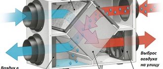
There are also air heaters that operate on the principle of recovery: this is the recovery of heat from the room by transferring it to the supply air. Recovery is carried out without contact of two air environments.
More detailed information about the design and regulatory data of SNiP and GOST is presented in the article “Description of air heaters and supply ventilation piping units.”
Electric heater
The base is a heating element made of wire or spirals, an electric current passes through it. Cold street air is passed between the spirals, it is heated and supplied to the room.
The electric heater is suitable for servicing low-power ventilation systems, since no special calculations are required for its operation, since all the necessary parameters are indicated by the manufacturer.
The main disadvantage of this unit is the inertia between the heating filaments, which leads to constant overheating and, as a consequence, failure of the device. The problem is solved by installing additional compensators.
Water heater
The basis of a water heater is a heating element made of hollow metal tubes, through which hot water or steam is passed. Outside air comes from the opposite side. Simply put, air moves from top to bottom, and water moves from bottom to top. Thus, oxygen bubbles are removed through special valves.
The water duct heater is used in most large and medium-sized ventilation systems. This is facilitated by high productivity, reliability and maintainability of the equipment.
In addition to the heating element, the system includes a piping unit: (provides the supply of coolant to the exchanger), a pump, direct and check valves, shut-off valves and an automatic control unit. For climatic zones where the minimum temperature in winter drops below zero, a system is provided to prevent freezing of the working tubes.
Strapping methods
The piping is a frame made of reinforcement, with the help of which the flow of hot water is regulated. The piping unit helps to monitor the performance of the supply ventilation heater, control it and maintain the desired temperature in the building. The location of the piping units is determined by the installation location, air exchange diagram, and technical parameters of the equipment. There are 2 installation options:
- Recirculated air masses are mixed with supply air.
- Only indoor air is recirculated according to a closed principle.
Taking this into account, there are 2 methods of strapping:
- 2-way valves - with uncontrolled reverse water flow;
- 3-way valves - when controlling water flow in a boiler room or boiler room.
Some produce piping units of various modifications, which are entire sets consisting of valves (balancing and check valves, two and three-way), pumps, bypasses, ball valves, pressure gauges, and cleaning filters.
Scheme of piping heater units for supply ventilation. (Ball valves installed at the inlet and outlet allow you to shut off the water, and a thermomanometer allows you to control temperature and pressure)
If natural ventilation is well established, then there are much more opportunities for successful operation of the equipment. The correct choice of piping in such cases is effective both for heating large areas in production and for private houses and cottages.
The heater used for ventilation is usually connected to the heating system directly at the air intake point. If forced ventilation is in effect, the air heater can be installed anywhere. Heaters for supply ventilation allow you to create a comfortable temperature regime in both industrial and residential premises
It is only important to correctly decide on the choice of coolant, which will be the most effective (with minimal costs and maximum performance) under certain conditions. An automated system - such as a supply ventilation control panel with a water heater - will make the use of heating devices for supply ventilation convenient and safe
Principle of operation
A fan, a heat exchanger and a convector - this is what a water heating device looks like in general terms.
The operating principle of supply ventilation is as follows:
- The air flow enters special air intake grilles that prevent insects, small objects, birds, and animals from entering the ventilation channels.
- Filters clean the air from contaminants, harmful substances, and dust.
- The heater, using heat supplied from the water main, heats it to the desired temperature.
- The recuperator mixes the newly supplied air with the heated one.
- The fan supplies heated air masses into the room, and the diffuser distributes them evenly over the entire area.
- Sound absorbers reduce the sound power of a running installation.
- If the air supply is cut off, valves are activated to prevent cold air from entering the room.
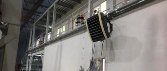
An example of using a VOLCANO air heater in a tire shop (water temperature +90 ºС)
The heater, which does not have its own heater, consists of two main elements:
- A heat exchanger, the design of which is represented by a system of metal tubes - water coming from the general heating system reaches the required temperature here.
- Built-in fan that disperses heated air flow throughout the entire area.
Advantages and disadvantages of water heaters
A water heater for fresh air ventilation has significant disadvantages that limit its use in residential premises:
- large dimensions;
- difficulty connecting to a common hot water supply system;
- the need for strict control of the temperature of the coolant in the water supply system.
However, to create a comfortable temperature in large premises (production workshops, greenhouses, shopping centers), the use of such heating systems is the most convenient, efficient, and economical.
The water heater does not load the electrical network, its breakdown will not cause a fire - these factors make the equipment safe to use.
Brief overview of current models and prices
Several models can be considered as examples:
- KSK-3. Spiral-rolled heater with 3 rows of tubes. A common domestic model, tested and reliable. The price of the device depends on its size, ranging from 5,000 to 3,700 rubles.
- Volcano mini. Polish device used to serve relatively small rooms. The cost is in the range of 20,000-30,000 rubles.
- Galletti AREO. Italian device equipped with a fan. It has an attractive appearance and has a low noise level. At the same time, prices for such devices are quite high and range from 80,000 rubles and above.
The use of water heaters allows solving problems with the preparation of supply air and organizing space heating. In addition, the devices are actively used in drying installations. Simplicity, unpretentiousness in operation and high efficiency made these devices leaders among industrial heating installations. Their long service life and the ability to be powered from different sources make them the most attractive devices among all alternative options.
Classification
To create an optimal microclimate in the building, a calorific heating system is used, that is, forced heating using equipment that is installed in air ducts.
Depending on what coolant is used, there are 4 types of heaters:
- Steam - used most often in industrial enterprises where steam production is provided for by technological processes.
- Electric - this option is the easiest to install (you only need a power source to heat the built-in heating elements), but it requires a lot of electricity consumption. The use of an electric heater is considered appropriate only in facilities whose area does not exceed 150 m²
- Water - this type of heater operates on the basis of hot water and is installed in ventilation systems with a rectangular or round cross-section in areas over 150 m². This type of heating is reliable, practical, easy to maintain and inexpensive.
A special feature of the heater is that the composition of the air flow coming from the street should not be sticky, fibrous, or contain solid particles. Permissible dust content is no more than 0.5 mg/m³. Minimum intake air temperature -20 °C.
When choosing a heater, the following factors are taken into account:
- room area;
- weather conditions in a given climate zone;
- ventilation power.
The heater is installed in the inside of the ventilation shaft, so it must correspond to its parameters (configuration and size).
If the performance is low, the device will not be able to warm up the air masses.
If it is not possible to install a heater with the required parameters, then several mechanisms with lower power are mounted in series.
Connection
The supply of air masses can be carried out in one of two options:
- Left version: the mixing unit and automatic control are installed on the left side, water is supplied from the top, outflow is at the bottom.
- Right execution: the indicated mechanisms are on the right, the water supply tube is at the bottom, the “return” is at the top.
The tubes are placed on the side where the air valve is installed.
Water heaters are divided into 2 types according to the type of valve:
- two-way – when connected to a general heating supply;
- three-way – with a closed method of heat supply (for example, when connected to a boiler).
The type of valve is determined by the characteristics of the system supplying heat. These include:
- Type of system.
- Water temperature at the beginning of the process and during outflow.
- With central water supply, the difference between the pressure in the water supply and outflow pipes.
- When autonomous - the presence or absence of a pump installed on the inflow circuit.
The installation diagram must provide for the inadmissibility of installation in the following cases:
- with vertical pipe inlet and outlet;
- with top air intake.
Such restrictions are due to the possibility of snow masses entering the equipment inflow and further leakage of melt water into the electronic unit.
Place of installation of a duct heater for supply ventilation in the air exchange system (if there is a possibility of the temperature dropping below normal, it is obligatory to install an anti-freeze thermostat)
To avoid malfunctions of the automation unit, the temperature sensor must be located in the inside of the air blowing element at a distance of at least 0.5 m from the inflow mechanism.
Online calculator for calculating the ventilation system
The next stage in the calculation of ventilation is the design of an air distribution network, consisting of the following components: air ducts, air distributors, fittings (adapters, turns, splitters.)
First, a ventilation duct diagram is developed, which is used to calculate the noise level, network pressure and air flow speed. The network pressure directly depends on the power of the fan used and is calculated taking into account the diameters of the air ducts, the number of transitions from one diameter to another, and the number of turns. The pressure through the network should increase with the length of the air ducts and the number of turns and transitions.
| Methodology for calculating the number of diffusers N = L / ( 2820 * V * d * d ), where N—number of diffusers, pcs; L—air flow, m3/hour; V—air velocity, m/sec; d — diffuser diameter, m. |
| Method for calculating the number of gratings N = L / ( 3600 * V * S ) where N—number of gratings; L—air flow, m3/hour; V—air velocity, m/sec; S is the live cross-sectional area of the grating, m2. |
Air performance
The calculation of the ventilation system begins with determining the air productivity (air exchange), measured in cubic meters per hour. For calculations, we will need a site plan, which indicates the names (purposes) and areas of all premises.
It is necessary to supply fresh air only to those rooms where people can stay for a long time: bedrooms, living rooms, offices, etc. Air is not supplied to the corridors, but is removed from the kitchen and bathrooms through exhaust ducts. Thus, the air flow pattern will look like this: fresh air is supplied to the living quarters, from there it (already partially polluted) enters the corridor, from the corridor into the bathrooms and the kitchen, from where it is removed through exhaust ventilation, taking with it unpleasant odors and pollutants. This air movement pattern provides air support for “dirty” rooms, eliminating the possibility of unpleasant odors spreading throughout the apartment or cottage.
For each living space, the amount of air supplied is determined. The calculation is usually carried out in accordance with MGSN 3.01.01. Since SNiP sets more stringent requirements, we will be guided by this document in our calculations. It states that for residential premises without natural ventilation (that is, where windows do not open), the air flow must be at least 60 m³/h per person. For bedrooms, a lower value is sometimes used - 30 m³/h per person, since in a state of sleep a person consumes less oxygen (this is permissible according to MGSN, as well as according to SNiP for rooms with natural ventilation). The calculation takes into account only people staying in the room for a long time. For example, if a large company gathers in your living room a couple of times a year, then there is no need to increase the ventilation performance because of them. If you want your guests to feel comfortable, you can install a VAV system that allows you to regulate the air flow separately in each room. With such a system, you can increase air exchange in the living room by reducing it in the bedroom and other rooms.
After calculating the air exchange for people, we need to calculate the air exchange by frequency (this parameter shows how many times a complete change of air occurs in the room within one hour). To ensure that the air in the room does not stagnate, it is necessary to ensure at least one air exchange.
Thus, to determine the required air flow, we need to calculate two air exchange values: by the number of people
and by
multiplicity
and, then select
the larger
of these two values:
- Calculation of air exchange by number of people:
L = N * Lnorm
, Where
L
required supply ventilation capacity, m³/h;
N
number of people;
Lnorm
air consumption rate per person:
- at rest (sleep) 30 m³/h;
typical value (according to SNiP) 60 m³/h;
- Calculation of air exchange by frequency:
L=n*S*H
, Where
L
required supply ventilation capacity, m³/h;
n
standardized air exchange rate: for residential premises - from 1 to 2, for offices - from 2 to 3;
S
room area, m²;
H
room height, m;
By calculating the required air exchange for each room served and adding the resulting values, we find out the overall performance of the ventilation system. For reference, typical performance values of ventilation systems:
- For individual rooms and apartments from 100 to 500 m³/h;
- For cottages from 500 to 2000 m³/h;
- For offices from 1000 to 10000 m³/h.
Frontal section
2. Selection and calculation of air heaters - stage two. Having determined the required thermal power of the air supply unit’s water heater to heat the required volume, we find the frontal cross-section for air passage. Frontal section is a working internal section with heat-dissipating tubes through which flows of forced cold air directly pass. f (m²) = G / v G - mass air flow, kg/hour; v - mass air velocity - for finned heaters is taken in the range of 3 - 5 (kg/m²•s). Acceptable values are up to 7 - 8 kg/m²•s.
An example of selection and calculation of a KSk air heater. Step-2
Select a suitable KSk supply ventilation air heater for heating 16,000 m³/hour from a temperature of -25°C to +23°C. The coolant is hot water with a schedule of 95°C at the inlet to the air heater, 60°C at the outlet. 2. Calculation of the frontal cross-section for air passage. We select the required cross-sectional area of the KSk heater for a mass air flow of 20800 kg/hour. We take the mass velocity to be 3.6 kg/m²•s. f (m²) = (20800/3600) / 3.6 = 1.605 m² 20800 - mass air flow, kg/hour; 3.6—air mass velocity, kg/m²•s. From the calculation, the required frontal cross-sectional area for air passage was 1.605 m². Next, based on the data from the table below, we select a KSk heater suitable for this section. The most suitable models are KSk 2-11, KSk 3-11 and KSk 4-11 (the frontal cross-sectional area of these heat exchangers is 1,660 m²).
Below is a table with data on two, three and four-row air heaters of the KSk-02-HL3 type manufactured by T.S.T. LLC. The table shows the main technical characteristics for the calculation and selection of all models of these heat exchangers: heating surface area and frontal section, connecting pipes, manifold and free cross-section for water passage, length of heat-heating tubes, number of strokes and rows, weight. Ready-made calculations for various volumes of heated air, incoming air temperature and coolant graphs can be viewed by clicking on the model of the ventilation heater you have chosen from the table.
| Heater name | Area, m² | Heat transfer element length (clear), m | Number of strokes through the internal coolant | Number of rows | Weight, kg | ||||
| heating surfaces | frontal section | collector sections | pipe cross-section | free cross-section (average) for coolant passage | |||||
| KSk 2-1 | 6.7 | 0.197 | 0.00152 | 0.00101 | 0.00056 | 0.530 | 4 | 2 | 22 |
| KSk 2-2 | 8.2 | 0.244 | 0.655 | 25 | |||||
| KSk 2-3 | 9.8 | 0.290 | 0.780 | 28 | |||||
| KSk 2-4 | 11.3 | 0.337 | 0.905 | 31 | |||||
| KSk 2-5 | 14.4 | 0.430 | 1.155 | 36 | |||||
| KSk 2-6 | 9.0 | 0.267 | 0.00076 | 0.530 | 27 | ||||
| KSk 2-7 | 11.1 | 0.329 | 0.655 | 30 | |||||
| KSk 2-8 | 13.2 | 0.392 | 0.780 | 35 | |||||
| KSk 2-9 | 15.3 | 0.455 | 0.905 | 39 | |||||
| KSk 2-10 | 19.5 | 0.581 | 1.155 | 46 | |||||
| KSk 2-11 | 57.1 | 1.660 | 0.00221 | 0.00156 | 1.655 | 120 | |||
| KSk 2-12 | 86.2 | 2.488 | 0.00236 | 174 | |||||
| Heater name | Area, m² | Heat transfer element length (clear), m | Number of strokes through the internal coolant | Number of rows | Weight, kg | ||||
| heating surfaces | frontal section | collector sections | pipe cross-section | free cross-section (average) for coolant passage | |||||
| KSk 3-1 | 10.2 | 0.197 | 0.00164 | 0.00101 | 0.00086 | 0.530 | 4 | 3 | 28 |
| KSk 3-2 | 12.5 | 0.244 | 0.655 | 32 | |||||
| KSk 3-3 | 14.9 | 0.290 | 0.780 | 36 | |||||
| KSk 3-4 | 17.3 | 0.337 | 0.905 | 41 | |||||
| KSk 3-5 | 22.1 | 0.430 | 1.155 | 48 | |||||
| KSk 3-6 | 13.7 | 0.267 | 0.00116 (0.00077) | 0.530 | 4 (6) | 37 | |||
| KSk 3-7 | 16.9 | 0.329 | 0.655 | 43 | |||||
| KSk 3-8 | 20.1 | 0.392 | 0.780 | 49 | |||||
| KSk 3-9 | 23.3 | 0.455 | 0.905 | 54 | |||||
| KSk 3-10 | 29.7 | 0.581 | 1.155 | 65 | |||||
| KSk 3-11 | 86.2 | 1.660 | 0.00221 | 0.00235 | 1.655 | 4 | 163 | ||
| KSk 3-12 | 129.9 | 2.488 | 0.00355 | 242 | |||||
| Heater name | Area, m² | Heat transfer element length (clear), m | Number of strokes through the internal coolant | Number of rows | Weight, kg | ||||
| heating surfaces | frontal section | collector sections | pipe cross-section | free cross-section (average) for coolant passage | |||||
| KSk 4-1 | 13.3 | 0.197 | 0.00224 | 0.00101 | 0.00113 | 0.530 | 4 | 4 | 34 |
| KSk 4-2 | 16.4 | 0.244 | 0.655 | 38 | |||||
| KSk 4-3 | 19.5 | 0.290 | 0.780 | 44 | |||||
| KSk 4-4 | 22.6 | 0.337 | 0.905 | 48 | |||||
| KSk 4-5 | 28.8 | 0.430 | 1.155 | 59 | |||||
| KSk 4-6 | 18.0 | 0.267 | 0.00153 (0.00102) | 0.530 | 4 (6) | 43 | |||
| KSk 4-7 | 22.2 | 0.329 | 0.655 | 51 | |||||
| KSk 4-8 | 26.4 | 0.392 | 0.780 | 59 | |||||
| KSk 4-9 | 30.6 | 0.455 | 0.905 | 65 | |||||
| KSk 4-10 | 39.0 | 0.581 | 1.155 | 79 | |||||
| KSk 4-11 | 114.2 | 1.660 | 0.00221 | 0.00312 | 1.655 | 4 | 206 | ||
| KSk 4-12 | 172.4 | 2.488 | 0.00471 | 307 | |||||
What should we do if, when calculating, we get the required cross-sectional area, but in the table for selecting KSk air heaters, there are no models with this indicator. Then we accept two or more air heaters of the same number so that the sum of their areas corresponds or approaches the desired value. For example, when calculating, we got the required cross-sectional area - 0.926 m². There are no air heaters with this value in the table. We take two KSk 3-9 heat exchangers with an area of 0.455 m² (in total this gives 0.910 m²) and install them in parallel over the air. When choosing a two, three or four row model (same heater numbers - have the same frontal cross-sectional area), we focus on the fact that KSk4 heat exchangers (four rows) at the same incoming air temperature, coolant schedule and air capacity , heat it on average eight to twelve degrees more than KSk3 (three rows of heat-carrying tubes), fifteen to twenty degrees more than KSk2 (two rows of heat-carrying tubes), but have greater aerodynamic drag.
