To ensure more economical operation, modern boiler systems have auxiliary elements: a water economizer and an air heater, which serve to heat water and air, respectively; devices for fuel supply and ash removal, for cleaning flue gases and feed water; thermal control devices and automation equipment that ensure normal and uninterrupted operation of all parts of the boiler room.
Depending on the use of their heat, boiler houses are divided into energy, heating and industrial and heating.
Energy boiler houses supply steam to steam power plants that generate electricity, and are usually part of a power plant complex. Heating and industrial boiler houses are found in industrial enterprises and provide heat for heating and ventilation systems, hot water supply to buildings and production processes. Heating boiler houses solve the same problems, but serve residential and public buildings. They are divided into free-standing, interlocking, i.e. adjacent to other buildings, and built into buildings. Recently, more and more often, separate enlarged boiler houses are being built with the expectation of servicing a group of buildings, a residential area, or a microdistrict.
The installation of boiler rooms built into residential and public buildings is currently permitted only with appropriate justification and agreement with the sanitary inspection authorities.
Low-power boiler houses (individual and small group) usually consist of boilers, circulation and feed pumps and draft devices. Depending on this equipment, the dimensions of the boiler room are mainly determined.
Classification of boiler installations
Boiler installations, depending on the nature of consumers, are divided into energy, production and heating and heating. Based on the type of coolant produced, they are divided into steam (for generating steam) and hot water (for producing hot water).
Power boiler plants produce steam for steam turbines in thermal power plants. Such boiler houses are usually equipped with high- and medium-power boiler units that produce steam with increased parameters.
Industrial heating boiler systems (usually steam) produce steam not only for industrial needs, but also for heating, ventilation and hot water supply.
Heating boiler systems (mainly hot water, but they can also be steam) are designed to service heating systems for industrial and residential premises.
Depending on the scale of heat supply, heating boiler houses are local (individual), group and district.
Local boiler houses are usually equipped with hot water boilers that heat water to a temperature of no more than 115 °C or steam boilers with a working pressure of up to 70 kPa. Such boiler houses are designed to supply heat to one or more buildings.
Group boiler systems provide heat to groups of buildings, residential areas or small neighborhoods. They are equipped with both steam and hot water boilers with higher heating capacity than boilers for local boiler houses. These boiler rooms are usually located in specially constructed separate buildings.
District heating boiler houses are used to supply heat to large residential areas: they are equipped with relatively powerful hot water or steam boilers.
Rice. 1. An example of the territory of a boiler room and some of its equipment
Rice. 2. Examples of the layout of some boiler houses and their equipment
Rice. 3. Examples of the layout of some boiler houses and their equipment
Rice. 4. Schematic diagrams of steam and hot water boiler houses
It is customary to conventionally show individual elements of a boiler installation schematic diagram in the form of rectangles, circles, etc. and connect them to each other with lines (solid, dotted), indicating a pipeline, steam lines, etc. There are significant differences in the basic diagrams of steam and water heating boiler plants. A steam boiler plant (Fig. 4, a) consisting of two steam boilers 1, equipped with individual water 4 and air 5 economizers, includes a group ash collector 11, to which the flue gases are approached through a collection hog 12. For suction of flue gases in the area between the ash collector 11 and smoke exhausters 7 with electric motors 8 are installed in the chimney 9. To operate the boiler room without smoke exhausters, dampers 10 are installed.
Steam from the boilers through separate steam lines 19 enters the common steam line 18 and through it to the consumer 17. Having given up heat, the steam condenses and returns through the condensate line 16 to the boiler room in the collecting condensation tank 14. Through pipeline 15, additional water from the water supply or chemical water treatment is supplied to the condensation tank (to compensate for the volume not returned from consumers).
In the case when part of the condensate is lost from the consumer, a mixture of condensate and additional water is supplied from the condensation tank by pumps 13 through the supply pipeline 2, first into the economizer 4, and then into the boiler 1. The air required for combustion is sucked in by centrifugal blower fans 6 partially from the room boiler room, partly from the outside and through air ducts 3, it is supplied first to air heaters 5, and then to the boiler furnaces.
The water heating boiler installation (Fig. 4, b) consists of two water heating boilers 1, one group water economizer 5, serving both boilers. Flue gases leaving the economizer through a common collection duct 3 enter directly into the chimney 4. Water heated in the boilers enters the common pipeline 8, from where it is supplied to the consumer 7. Having given off heat, the cooled water through the return pipeline 2 is sent first to the economizer 5 , and then again into the boilers. Water is moved through a closed circuit (boiler, consumer, economizer, boiler) by circulation pumps 6.
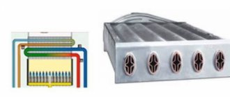
Rice. 5. Diagram of a steam boiler installation : 1 - circulation pump; 2 - firebox; 3 - superheater; 4 - upper drum; 5 — water heater; 6 — air heater; 7 - chimney; 8 — centrifugal fan (smoke exhauster); 9 - fan for supplying air to the air heater
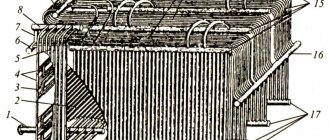
In Fig. Figure 6 shows a diagram of a boiler unit with a steam boiler having an upper drum 12. At the bottom of the boiler there is a firebox 3. To burn liquid or gaseous fuel, nozzles or burners 4 are used, through which the fuel together with air is supplied to the firebox. The boiler is limited by brick walls - lining 7.
When fuel is burned, the heat released heats water to a boil in tube screens 2 installed on the inner surface of the firebox 3 and ensures its transformation into water vapor.
Fig 6. Diagram of the boiler unit
Flue gases from the furnace enter the boiler flues, formed by lining and special partitions installed in the pipe bundles. When moving, the gases wash the bundles of pipes of the boiler and superheater 11, pass through the economizer 5 and the air heater 6, where they are also cooled due to the transfer of heat to the water entering the boiler and the air supplied to the firebox. Then, the significantly cooled flue gases are removed through the chimney 19 into the atmosphere using a smoke exhauster 17. Flue gases can be removed from the boiler without a smoke exhauster under the influence of natural draft created by the chimney.
Water from the water supply source through the supply pipeline is supplied by pump 16 to the water economizer 5, from where, after heating, it enters the upper drum of the boiler 12. Filling of the boiler drum with water is controlled by a water indicator glass installed on the drum. In this case, the water evaporates, and the resulting steam is collected in the upper part of the upper drum 12. Then the steam enters the superheater 11, where due to the heat of the flue gases it is completely dried and its temperature rises.
From the superheater 11, steam enters the main steam line 13 and from there to the consumer, and after use it is condensed and returned to the boiler room in the form of hot water (condensate).
Losses of condensate from the consumer are replenished with water from the water supply or from other water supply sources. Before entering the boiler, water is subjected to appropriate treatment.
The air required for fuel combustion is taken, as a rule, from the top of the boiler room and supplied by fan 18 to air heater 6, where it is heated and then sent to the furnace. In boiler houses of small capacity, there are usually no air heaters, and cold air is supplied to the firebox either by a fan or due to the vacuum in the firebox created by the chimney. Boiler installations are equipped with water treatment devices (not shown in the diagram), control and measuring instruments and appropriate automation equipment, which ensures their uninterrupted and reliable operation.
Rice. 7. Technological diagram of the production and heating boiler house
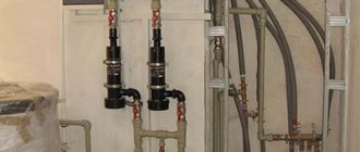
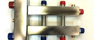
For proper installation of all elements of the boiler room, use a wiring diagram, an example of which is shown in Fig. 9.
Rice. 9. An example of an installation diagram for an autonomous gas boiler house
Hot water boiler systems are designed to produce hot water used for heating, hot water supply and other purposes.
To ensure normal operation, boiler rooms with hot water boilers are equipped with the necessary fittings, instrumentation and automation equipment.
A hot water boiler house has one coolant - water, in contrast to a steam boiler house, which has two coolants - water and steam. In this regard, the steam boiler room must have separate pipelines for steam and water, as well as tanks for collecting condensate. However, this does not mean that the circuits of hot water boiler houses are simpler than steam ones. Water heating and steam boiler houses vary in complexity depending on the type of fuel used, the design of the boilers, furnaces, etc. Both steam and water heating boiler systems usually include several boiler units, but not less than two and no more than four or five . All of them are connected to each other by common communications - pipelines, gas pipelines, etc.
The design of lower power boilers is shown below in paragraph 4 of this topic. To better understand the structure and principles of operation of boilers of different power, it is advisable to compare the structure of these less powerful boilers with the structure of the higher power boilers described above, and find in them the main elements that perform the same functions, as well as understand the main reasons for the differences in designs.
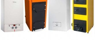
Installing a gas boiler in the kitchen: room requirements
In the kitchen it is permissible to place gas boilers with a power of up to 30 kW and which are equipped with a combustion chamber of any design, with the boiler located both on the floor and on the wall.
The requirements for installing a gas boiler in the kitchen mostly relate to volume and ventilation
The following requirements apply to the premises:
- Ceiling height is within 2.5 meters.
- The volume of the room is not less than 15 cubic meters.
- Effective ventilation system.
- Availability of fresh ventilation.
When hanging boilers on walls, the latter must be constructed of fire-resistant materials. The distance to the side walls should be at least 0.1 meters. In the absence of such walls, installation of boilers is allowed, provided that there is a non-flammable gap of 5 cm between the flammable walls and the boiler itself. This could be a layer of plaster or a non-flammable screen made of fire-resistant material.
The screen can be made of sheet steel; the dimensions of the sheet should be 0.7 meters larger in height and 0.1 meters larger on all other sides, compared to the dimensions of the boiler itself. Between the sheet steel and the combustible base, a layer of fire-resistant material, about 3 cm thick, is laid. This may be asbestos or other fire-resistant material.
Free-standing combustion chambers: requirements
A separate boiler room can be like this.
A separate room for arranging a boiler room will be required if the boiler power is more than 200 kW. Such buildings must have the following parameters:
- The construction is made entirely of non-combustible materials.
- The volume of the room is at least 15 cubic meters with the addition of 0.2 cubic meters per kilowatt of power.
- The ceiling location is not lower than 2.5 meters from the floor level.
- The glazing area is not less than 0.03 square meters per cubic meter of volume.
- The window is equipped with a window or transom.
- The boiler is mounted on a separate foundation, the height of which is no more than 15 cm compared to the height of the floor.
- If the boiler weighs no more than 200 kilograms, then it can be installed directly on the floor if it is concrete.
- The heating system must include an emergency gas shut-off sensor.
- Doors should not be reinforced; they should be loosely secured.
- Availability of an effective ventilation system.
Permission to put heating equipment into operation will be issued only if all requirements are met.