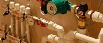
The main task of the heating system of an apartment or private house is the competently organized heating of all rooms and the normal functioning of each line. The functionality of each unit, uniform heat distribution, and the ability to repair individual units are provided by special boiler manifolds installed in multi-room residential and industrial buildings.
Using this device you can evenly distribute heat in the room
The right boiler room. How to prepare for gas start-up
Gas boilers used to heat a home and produce hot water are potentially dangerous equipment.
Therefore, these units are subject to certain standards and rules governing their installation and operation. And if violations are detected, the equipment simply will not be connected until they are eliminated, and it is unknown how long the gasification process will drag on. What a proper boiler room should be like and where else gas boilers can be placed, and where it is strictly prohibited - we’ll figure it out. 11 cards May 27, 2022, 15:30
1 . Where can I make a boiler room?
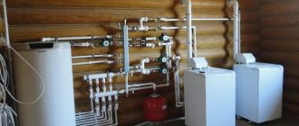
Most often, boiler rooms are included in the layout of the house at the design stage, choosing the optimal location taking into account cardinal directions and practicality. The boiler room, as a technical room, is located mainly on the north or northeast side in order to minimize the impact of wind and negative temperatures on living rooms. Also, extensions are often made for boiler rooms in order to completely remove the “dirty” room from the house. Some go even further - they place engineering equipment in a separate utility unit, and the lines with the coolant are carefully insulated. With the advent of high-tech, powerful, but at the same time compact gas boilers, in small houses, where every meter of free space counts, boiler rooms are not built at all.
2. Where should the gas inlet be?
When the boiler room is initially planned and reflected in the project, no problems arise - like other parameters, the mortgage for the gas pipe is installed during the construction process. But even today they stubbornly continue to first “jump”, that is, build without a clear idea of the result at all, and then try to “adjust” the dubious layout to their needs and the requirements of gas workers. Also, difficulties with the placement of the input arise when reconstructing outdated housing stock or switching from one coolant to another. Regardless of anything, the gas pipeline entry into a private house must be done either in the room where the gas-using equipment is located, or in an area adjacent to it, but connected by an open opening. That is why it is so common to see houses whose facades are literally “girdled” with yellow gas pipes. To avoid such decor, you should still think about where to place the boiler at the very beginning.
3. How does a boiler room differ from a heat generator room?
Heating equipment, regardless of design and type of fuel, operates on the same principle - in one way or another it consumes energy and generates heat. Accordingly, the separate room in which it is installed is called a heat generator room in modern regulatory documents. But it’s more difficult to pronounce this word, because heat generators are everywhere, boilers, and heat generators in everyday life are boiler rooms. This does not change the meaning, but when ordering an internal gasification project, it is still worth using the official terminology.
4 . What are the minimum dimensions of a boiler room?
Simply taking and hanging a boiler in any nook will not work - the boiler room must be of a certain size and volume. The specific area of the room is determined based on the conditions of convenience for installation, maintenance and operation of the equipment installed in it; at least one hundred square meters can be allocated, if there is such a possibility and necessity. But it is impossible to make the boiler room less than the permissible minimum, and it is clearly stated in the joint venture:
- The volume of the room is at least 15 m³ with a height of 2.5 m for boilers with an open combustion chamber - the resulting area is 6 m², but for convenience, 7-10 m² is recommended.
- The volume of the room is not less than 7.5 m³, with the same height for boilers with a closed combustion chamber - although the standards allow, it is impractical to make a separate boiler room of only three square meters.
With a closed chamber, less air is needed for ventilation, but using the boiler and servicing it is still more convenient in a spacious room. And if the boiler room is combined, with storage systems, or is used as a utility room or laundry room (ironing room), you need no less than 12 m², and better yet, all 15 m², if the area of the house allows.
5 . Is a window necessary?
Yes, the presence of a window and natural light in the boiler room is also a prerequisite. When installing a boiler with a power of more than 60 kW, for each cubic meter of room volume there should be 0.03 square meters of glazing (glass dimensions). That is, for a standard boiler room with a volume of 15 m³, you need at least 0.45 m². And if the boiler room is not 6 m² in area, but 12 m², then the glazing should cover 0.9 m² and must have a window or an opening flap in case of burst ventilation in the event of a gas leak. At the same time, window structures must be easily removable, so that in the event of a blast wave they will be knocked out, not the walls. Therefore, only ordinary double-glazed windows are installed in the boiler room, and not armored or tempered triplexes.
For boilers of lower power, the area of individual glass is selected based on its thickness:
- 3 mm – 0.8 m²;
- 4 mm – 1.0 m²;
- 5 mm – 1.5 m²
6. Is the ventilation natural or forced?
Like natural lighting, one of the basic requirements for boiler rooms is the presence of natural ventilation. The exhaust is in the volume of three air changes per hour, the inflow is in the volume of the exhaust. If the boiler has an open combustion chamber, additional combustion air must be added to this volume. For boilers with a power of more than 60 kW, the dimensions of the exhaust and supply air outlets are determined by calculation. Plus, when using such boilers, the room must be equipped with an air pollution control system, which will shut off the gas supply in the event of an emergency.
7. Any door or are there any restrictions?
Eat. The door from the boiler room should only open outward; a gap or hole in the leaf of at least 0.02 m² is required in the lower part. If the boiler room is located in a basement or basement, and its power exceeds 150 kW, the exit must be outside.
8 . What to build from?
Ideally, the walls and ceilings of the boiler room should be made of non-combustible materials, which is quite problematic given the growing popularity of frame and wooden houses. Therefore, if the walls are not brick or block under plaster, when finishing it is necessary to use fireproof materials that can withstand high temperatures or fireproof screens. In the second case, the insulation should protrude beyond the dimensions of the boiler body by 10 cm on the sides and bottom and by 70 cm on top. When the boiler is floor-standing, the base must also be fireproof.
9 . And if not in the boiler room, then where?
Gas boilers with a power of up to 60 kW, according to current rules, do not require placement in a boiler room, which is very convenient for many. When the area of the house is less than fifty to seventy square meters, it is quite difficult to allocate even six meters for a boiler. An alternative is usually the kitchen - the unit is hung on the wall and hidden in a kitchen cabinet or left in plain sight, fortunately, the design of modern boilers allows it. To avoid problems with connection, the kitchen must meet safety requirements.
- Ceiling height – from 2.5 m.
- The volume of the room for a boiler with a closed combustion chamber is from 15 m³.
- The volume of the room for a boiler with an open combustion chamber is 6 m³ more.
- Glazing – 0.3 m² of glass for every 10 m² of kitchen area.
- The width of the entrance door is 0.8 m.
Thermal insulation - the wall under the boiler and next to it (in a corner location) must be thermally insulated.
10 . Well, then why bother with a boiler room?
Because installation in the kitchen is an allowed compromise with its pros and cons, and not a full-fledged alternative to the boiler room. In a private house, all engineering support is individual, and even if the boiler is a double-circuit one, there is also pumping equipment, a water treatment system, and a boiler piping or a heated floor collector. And all this “goodness” is much more convenient to operate and use when collected in one technical room.
eleven . I want to hang the boiler in the bathroom, is that possible?
No you can not. Gas equipment is not allowed in the bathroom or toilet, even if the boiler is the most sophisticated. But the boiler room can be installed even in the basement, even in the basement, on any floor, including the attic or in an unheated extension. But from a practical point of view, neither the attic nor the second (third) floor is used for these purposes, and if there is no space for a boiler room, you will have to huddle in the kitchen.
Installation of the collector block
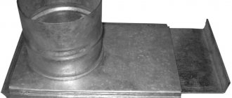
The heating collector is installed in close proximity to the boiler . Radiator pipes from the heater are often laid along the floor, after which the structure is concreted and insulated, which minimizes heat loss. The collector block itself is mounted in a specially prepared panel or wall niche. A special shield can be hinged or built-in, equipped with a door and side stamping, or open. If it is not possible to install a cabinet, then the manifold block is fixed on the wall at a small height from the floor.
If the building is multi-story, then the distributor will be installed on each floor of the house, which will allow heating any room. Such a system will allow you to regulate, connect and disconnect one or more heating radiators, the entire room, a full circuit. This eliminates the need to turn off the coolant supply to other heating sources. Storerooms, hallways, corridors, and wardrobes are used as premises for installing the distribution manifold.
Calculation of collectors in heat supply systems.
Another common comment from the expert:
“Perform reservoir calculations. Or confirm the diameters of the collectors by calculation.”
Let's start with the regulatory framework:
TO 70238424.27.060.003-2008 Heating points of heating networks. Conditions of creation. Norms and requirements
7.70. The cross-sectional area of the distribution manifold body is taken to be no less than the sum of the cross-sectional areas of the outlet pipelines, and of the collection manifold - the cross-sectional areas of the inlet pipelines.
SP 41-101-95. Design of heating points
4.60 The cross-sectional area of the distribution manifold body is taken to be no less than the sum of the cross-sectional areas of the outlet pipelines, and of the collection manifold - the cross-sectional areas of the inlet pipelines.
For example, we determine the diameter of the collector from which they depart or approach.
One pipe DN25,
One pipe DN 50.
We calculate the required cross-section using the formula for determining the area of a circle.
Cost of equipment
Many homeowners are mistaken in believing that a distribution manifold for a boiler room costs exorbitant amounts of money. In plumbing stores you can find many models without any special bells and whistles , which will cost only 200-500 rubles. Such equipment will not have regulation mechanisms, thermal heads and other additional elements, and they are designed for a maximum of 2-3 circuits.
Models with advanced functionality will cost the owner of a home or industrial building who wants to organize a competent heating system approximately 4-5 thousand rubles. A long pipe with several upper and lower outlets will be equipped with thermal heads, flow meters, arrows and other parts. Such designs are often produced by Russian manufacturers or brands from neighboring countries. The most expensive is considered to be imported equipment with automatic adjustment, which will cost 10-16 thousand rubles.
Calculation of the gas manifold in the boiler room
Converting pressure units from different number systems
Calculation of the compressibility coefficient according to GOST 8.563.2-97
Gas pipeline volume calculation
Program for correcting gas meter readings
A program that allows you to select the necessary components for a gas metering unit in a matter of seconds.
A program for calculating gas losses for technological needs in accordance with RD 153-39.4-079-01. VERSION 1.0
A program for calculating standardized pressure drops on various types of gas meters.
Determination of boiler power and boiler volume
Program for calculating paint consumption. Version 1.2
Estimate program - "GazSmeta", to determine the cost of designing gas supply systems.
Calculation of the strength of a steel gas pipeline
Program for calculating a gas reservoir
Calculation of the distance between gas pipeline supports
Program for calculating errors of a gas metering unit in accordance with the rules PR 50.2.019-2006
A program for determining the explosion hazard categories of premises in accordance with NPB 105-95 “Determination of categories of premises and buildings by explosion and fire hazard.”
Program for calculating the cross-section of a louvered (ventilation) grille for a boiler room - RGR Version 1.0
Boiler room gas manifold
The gas manifold is designed to supply gas to gas-using industrial installations.
The technical result of the proposed manifold design is to increase the level of operational safety of gas-using equipment by ensuring continuous monitoring of the tightness of the gas manifold purge valve.
The gas manifold consists of a pipeline 1, lower pipes 2 that provide gas supply to the boiler units 3, a first purge valve 4 installed in the end part of the pipeline 1 and connected at the outlet through the purge pipeline 5 to the atmosphere, a second purge valve 6 installed in series with the first purge valve valve 4, device 7 for measuring and signaling gas pressure between the first and second purge valves 4 and 6. Boiler units 3 are connected to pipeline 1 of the gas manifold through lower pipes 2, shut-off valve 8, gas pressure fittings 9 of the boiler burners, connected through purge valves 10 and purge pipeline 5 with atmosphere. 1 ill.
The utility model relates to the energy sector, and in particular to collectors that provide gas supply to gas-using installations for industrial purposes, for example, to boilers.
Industrial gas collectors (Ryabtsev N.I. Gas equipment, instruments and fittings, M., 1963) of gas-using installations consist of a pipeline, lower pipes that supply gas to the burners of gas-using installations, a purge valve installed in the final part of the pipeline, and the purge outlet The valve is connected to the atmosphere through the purge pipeline.
A leak in the purge valve of gas manifolds leads to negative consequences, namely:
— Creates the preconditions for unauthorized and dangerous gas ingress into production premises, into the furnaces of idle boiler units through open purge valves and faulty gas shut-off valves of the burner.
— Leads to uncontrolled leakage (losses) of gas into the atmosphere, reducing the economic efficiency of gas-using equipment.
In practice, there are known cases of spontaneous occurrence of a torch when checking the igniter spark on idle boiler units due to a leak in the purge valve shutter and a malfunction of the shut-off solenoid valve on the boiler igniter.
two purge valves, with a shut-off valve and gas pressure fittings of the burners installed sequentially on each downpipe; the purge pipeline is connected through the first purge valve to the cavity of the main pipeline, and through the second purge valve to the cavity of the downpipe between the shut-off valve and the gas pressure fittings of the burners.
The disadvantage of the known gas manifold is the inability to continuously monitor the tightness of the purge valve valve, which does not provide the required level of safety for the operation of gas-using installations, since the leakage of the purge valve valve is one of the reasons for gas leakage into the atmosphere, creating the preconditions for dangerous unauthorized gas ingress into production premises, combustion chambers of installations, for example, in boiler furnaces.
The objective of this utility model is to increase the level of safety of operation of gas-using equipment. The technical result that provides a solution to this problem is continuous monitoring of the tightness of the shutter of the purge valve of the gas manifold.
Achieving the stated technical result and solving the problem is ensured by the fact that the gas manifold of the boiler room, containing a main gas pipeline with a block of downpipes and a purge pipeline with two purge valves, and on each downpipe a shut-off valve and gas pressure fittings of the burners are installed in series the pipeline is connected through the first purge valve to the cavity of the main pipeline, and through the second purge valve to the cavity of the lower pipes between the shut-off valve and the gas pressure fittings of the burners, according to the utility model it
additionally contains a third purge valve and a signal pressure sensor, wherein the third purge valve is installed between the first purge valve and the purge pipeline, and the signal pressure sensor is installed between the first and third purge valves.
The introduction of a third purge valve and a pressure signal sensor, wherein the third purge valve is installed between the first purge valve and the purge pipeline, and the signal pressure sensor is installed between the first and third purge valves, makes it possible to continuously monitor the tightness of the purge valve valve of the gas manifold and issue an alarm signal when the specified one is depressurized shutter This ensures increased safety of operation of gas-using equipment
The figure shows a diagram of the gas manifold of gas-using equipment, for example boilers.
The gas manifold consists of a pipeline 1, lower pipes 2 that provide gas supply to the boiler units 3, a first purge valve 4 installed in the end part of the pipeline 1 and connected at the outlet through the purge pipeline 5 to the atmosphere, a second purge valve 6 installed in series with the first purge valve valve 4, device 7 for measuring and signaling gas pressure between the first and second purge valves 4 and 6. Boiler units 3 are connected to pipeline 1 of the gas manifold through lower pipes 2, shut-off valve 8, gas pressure fittings 9 of the boiler burners, connected through purge valves 10 and purge valve pipeline 5 with atmosphere.
During operation of the boiler units, purge valves 4 and 6 of the gas manifold and purge valves 10 of operating boilers
must be closed, and the purge valves of 10 idle boilers (according to the requirements of regulatory documents) must be open.
If the shutter of the first purge valve 4 is tight, the excess gas pressure at its outlet is practically zero, the output signal of the device 7 for measuring and signaling the gas pressure is also zero. If a leak occurs in the shutter of the purge valve 4, the gas pressure at its outlet increases; a signal equal to one appears at the output of the device 7 for measuring and signaling the gas pressure, warning service personnel about the need to perform appropriate actions and repair and maintenance measures.
The proposed technical solution contains known elements and can be implemented on the basis of standard industrial devices.
Gas manifold of the boiler room, containing a main gas pipeline with a block of downpipe pipes and a purge pipeline with two purge valves, with a shut-off valve and gas pressure fittings of the burners installed in series on each standpipe, the purge pipeline is connected through the first purge valve to the cavity of the main pipeline, and through the second purge valve valve - with a cavity of lower pipes between the shut-off valve and the gas pressure fittings of the burners, characterized in that it additionally contains a third purge valve and a signal pressure sensor, with the third purge valve installed between the first purge valve and the purge pipeline, and the signal pressure sensor - between the first and third purge valves.
Installation features
When organizing a collector block for a country house, difficulties may arise during the installation of the distributor for the boiler room. Installing a collector requires the homeowner to comply with certain rules and requirements:
- Installation of a circulation pump, which is necessary for a system with multiple circuits.
- Installation of an expansion tank located in front of the pumping station on the return water supply line.
- Purchase of additional pipeline elements, shut-off valves, automation (if necessary).
- Installation of collector groups in special boxes made of metal (installation type can be mortise or hinged).
- Decorating a box with a collector, which will make the design more aesthetically pleasing.
- Selection of the room where the distribution element and components will be installed, in which there must always be normal humidity (corridor, pantry, dressing room, etc.).
- Pipe supply through special holes in the side walls of the collector box.
Don't forget about the installation rules
Despite the simplicity of the process, the design and installation should be carried out by professionals who can correctly position the panel with the collector, connect it to the boiler room and heating sources. High professionalism of installers will reduce installation time, increase the efficiency of using the boiler manifold, and reduce the vulnerability of the expansion tank to turbulence of water flows.
Economical and reliable boiler manifolds are devices without which it is difficult to imagine a normally functioning heating system in a private home or country cottage. Functional equipment allows you to precisely regulate the heating of each room and the entire residential or industrial building. Thanks to its thoughtful design and ease of use, emergency repairs can be carried out with minimal damage without shutting down the entire heating system. In addition, distribution combs are relatively inexpensive.
Hydraulic calculation of the boiler room gas pipeline
On the axonometric diagram of the boiler room gas pipeline (see appendix K), we select the main direction. We divide the direction into design sections, considering as such the gas manifold and the descent to the burner of the boiler furthest from the main control unit. Find the actual lengths of sections lф, m:
We calculate the estimated lengths of the direction sections, m:
We determine the gas consumption of each boiler, m 3 / h:
Vk = 168.3 / 2 = 84.15 m 3 / h
We determine the required gas pressure at the outlet of the gas control unit, Pa:
where Rp.hor. – value of the connecting pressure of the most distant burner, Pa; for burner brand GG-1 Rp.gor. = 1220 Pa (see appendix I);
kp. – pressure loss accounting factor, for low-pressure gas pipelines kp.=0.4÷0.5 [xvi];
Rn. = 1220* (1 + 0.44) + 147.4 = 1904 Pa.
We find the average pressure loss in the direction, Pa/m:
lр. – estimated length of the gas pipeline section, m.
Table 4.1 – Hydraulic calculation of the boiler room gas pipeline
Note: a) the diameter of the lowerings to the boiler burners is taken equal to 57 * 3 mm, the diameter of the collector is equal to 70 * 3 mm;
b) in the calculations, the maximum possible diameters for these cases were taken.
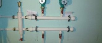
Typical collector device
The boiler room collector is a fairly large distribution center in which many working units are connected, usually made of pipes with a diameter of 100 mm. Typically, it includes the installation of two combs for distributing coolant and collecting it when leaving the system.
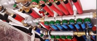
The supply comb is equipped with pumps to improve circulation, and the receiving comb is equipped with taps. Pressure gauges and temperature sensors must be installed. With the help of such a device, you can monitor the heating of your home in a civilized manner. Devices in the design of a typical boiler room manifold:
- mixing valve for selecting coolant temperature;
- circulation pump to increase pressure in the system;
- hydraulic separator;
- comb in the boiler room;
- weather-dependent automatics;
- expansion heating tank;
- expansion tank of the hot water supply circuit;
- pressure gauges;
- devices for trapping and removing air bubbles;
- couplings and fittings for adapting to different pipe diameters;
- heating make-up devices;
- group of devices for safe operation of the boiler;
- automatic control of circuit operation.
Hydraulic calculation of a gas pipeline: methods and methods of calculation + calculation example
To ensure balance and stability, all elements of the heating system must match each other in their throughput, which depends on the cross-section of the pipes. The basic principle by which the heating manifold should be calculated states: the distribution hydrocollector must have a cross-sectional area of the body equal to or greater than the total cross-sectional area of all outlet branches, and the cross-sectional area of the collection comb must not be less than the sum of the areas of the supply pipelines.
Failure to comply with this requirement when designing the collector will lead to insufficient coolant supply, which will greatly reduce the quality of heating.
Operating modes of hydraulic separator
The main objective of this design is the hydraulic separation of the boiler and consumer circuits. After performing such a separation, the system can operate in different modes when:
- boiler consumption = consumer consumption;
- boiler consumption
- boiler consumption>consumer consumption.
Some consider this flexibility to be one of the advantages of using a hydraulic arrow for heating a home. In reality, of all the listed options, only one is working. Let's look at why this is so.
Q boiler = Q consumers
Of course, equal flow rates of the two circuits is an ideal situation, but in practice the implementation of such a regime is impossible. Even if the resistance of the circuits and the performance of the pumps are selected in such a way as to equalize the flow, when one of the consumers or, for example, the thermal head of the radiator is turned on, all equality will come to naught.
Boiler Q
This mode, when the consumption of the heating device is less than what consumers require, is quite possible, but in no case should it be allowed. To understand why this situation is dangerous, let’s look at the principle of operation of the heating water arrow in this mode.
Let's assume that the boiler is capable of producing 30 liters of coolant per minute, while the heating system requires 90 l/min. In this case, the missing flow rate, namely 60 l/min, will be replenished by the system due to the reverse flow of the coolant, the temperature of which is approximately 20 degrees lower. Thus, water with a lower temperature will enter the consumer circuit, which forces it to increase fuel consumption and heat it to higher temperature parameters.
This mode of operation of the hydraulic separator in the heating system is noted by some “experts” as an advantage. They say that in this case it becomes possible to use a cheaper boiler with lower consumption. As we managed to find out, this approach is fundamentally wrong, since it can lead to excessive fuel consumption and, even worse, failure of the heating device.
Q boiler >Q consumers
The only correct mode of operation of the hydraulic separator is to use a boiler circuit with a slightly higher flow rate than required by the consumer circuit. In this case, excess coolant returns to the boiler through the return line, heating it. This is necessary in order to prevent thermal shock in transient mode, when a “cold” consumer (guest house, swimming pool, basement) is turned on. Simply put, so that the cold return flow does not harm the boiler, it is heated by a heated coolant.
Modifications of collector units
Before you begin assembling the collector assembly, it is necessary to determine its functional load. The equipment can be installed in several sections of the heating main. Based on this, the necessary equipment, dimensions and level of automation of the work cycle are selected.
In fact, for the full operation of such a node, two devices are needed. Using a comb, the coolant is distributed along the contours of the central supply pipeline. The return collector channel is represented by a collection mechanism and the point of departure of the cooled liquid into the boiler.
The collector heating circuit is selected based on the calculation of the required functionality and installation location. The choice of material for making the device does not affect the number of significant mechanisms
Installation of a homemade distribution group may be required when installing water-heated floors or for preparing standard heating with radiators.
Distinctive features of both options are their sizes and components:
- Boiler room. The welded manifold group is made of pipes with a diameter of up to 100 mm. A circulation pump and shut-off valves are installed on the supply side. The return ring is equipped with shut-off ball valves.
- Warm floor system. Similar equipment is present in this mixing unit. With its help, it is possible to significantly save on coolant consumption, especially if additional flow meters are installed. Read more about the mixing unit in a heated floor system in this article.
Each of these solutions provides an individual installation scheme. Correct installation of all elements can be carried out only after detailed calculations of all operating point parameters.
The comb can be made of the same material as the pipeline. If it is different, adapters will be used to connect the collector
There are also differences in the required number of circulation pumps. In the boiler room, each line is equipped with this device. For heated floors, only one installation is provided.
What is a hydraulic arrow in a heating system, device and diagram
The design of the hydraulic arrow is extremely simple. This is a piece of rectangular or round pipe that has four outlets - two on the side of the boiler circuit and two on the consumer side. Such an element can be placed both horizontally and vertically. Although the second option is more common, since in this case it is easier to install an air vent and a tap to remove sludge that accumulates in the lower part of the structure.
Sectional diagram of a hydraulic arrow for heating systems
Some manufacturers install two meshes inside the hydraulic separator. One serves for air separation, and the other for sludge separation. Although most often such a product is completely empty, since during operation the grids become clogged quite quickly and lose their effectiveness.
A hydraulic arrow is installed at the break in the connection line between the boiler and the collector, dividing the coolant flow between consumers. Sometimes the hydraulic separator and manifold are assembled in one housing. This simplifies installation and makes the overall design more compact.
An example of a diagram for manufacturing a hydraulic arrow with a manifold in one housing
What is calculated
This procedure is performed in relation to the following operating parameters of engineering communications.
- Fluid flow in individual segments of the water pipeline.
- Flow rate of the working fluid in pipes.
- The optimal diameter of the water supply system, which ensures an acceptable pressure drop.
Let us consider the methodology for calculating these indicators in detail.
Design Features
The manifold for a country house boiler room looks like a simple horizontal pipe with upper and lower outlets. Often such products are made of steel or brass alloys. The collector pipe is equipped with shut-off valves, which allow you to cut off the supply of hot media in a timely manner if a problem occurs or regulate the water pressure. Numerous outlets serve as distributors through which the boiler is connected to heating radiators, swimming pools and other objects to which heat is supplied.
This design consists of 8 elements
Other main and additional structural elements of distribution manifolds include:
- Shut-off valves, responsible for shutting off the flow of water on any circuit without stopping the supply of coolant to the remaining radiators and other heating sources.
- Control valves, which can be manual, semi-automatic or fully automatic.
- Auxiliary temperature sensors and regulators installed on taps.
- Valves for draining coolant and releasing air from pipes.
- A supply pipe that transports coolant from the boiler (boiler) to the heating circuits.
- A return pipe designed to pass cooled water through.
- Thermal heads responsible for regulating the degree of heating of the media.
- A hydraulic arrow that acts as a water distributor as it heats up.
The peculiarity of manifolds for heating boilers is the possibility of “extending” the structure. If the number of radiators or other heating sources increases, then you can independently purchase and install thermal heads, flow meters, etc.
In this video you will learn the specifics of the collector: