SHARE ON SOCIAL NETWORKS
FacebookTwitterOkGoogle+PinterestVk
The most important conditions for ensuring the proper functioning and efficient operation of the heating system are its proper installation and distribution. Today, many schemes are available that allow you to implement any heating project in accordance with the specifics and layout of the house. The maximum efficient output of the circuits can be provided by heating collectors, which are the subject of this article.
Using the distribution manifold, you can regulate the temperature, pressure and volume of the coolant
What is a collector heating system?
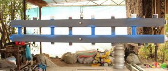
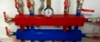
The heating manifold is represented by a volumetric comb, which consists of a supply element that distributes the coolant heated in the boiler for supply to the radiators, and a return part that returns the cooled coolant to the heat generator. The last component of the unit ensures uniform and smooth heating of each element in the system.
Various heating devices in the form of convectors, radiators, underfloor heating systems are connected to the distribution manifold
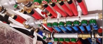
Using the comb distribution manifold, you can regulate the temperature, pressure and volume of the coolant, which allows you to control the heat supply to each individual room of the house. Due to its integration, various heating devices in the form of convectors, radiators, underfloor heating systems or panel heating options are connected to the distribution manifold. The dimensions of the device are determined by the number of circuits represented by pipes that are connected to it. The maximum number of elements can reach 12 pieces. In this case, the collector consists of two combs, each of which has 6 circuits.
Helpful advice! Some manufacturers produce manifolds with a large number of combs or a single product that is made to order.
Each outlet of the device has an outlet valve and a control or shut-off valve. The presence of these elements allows you to adjust the pressure inside each circuit and, if necessary, disconnect branches for repairs.
To increase system performance and gain control over all technological processes in each individual room, the comb body can be used as a platform for installing flow meters, heat meters, drainage or air outlet valves.
Each outlet of the device has an outlet valve and a control or shut-off valve
Types of collector units
Before considering the types of combs, we will indicate ways of their use in water heating systems of private houses and apartments:
- distribution and regulation of water temperature in underfloor heating circuits, abbreviated as TP;
- distribution of coolant to radiators using a radial (collector) circuit;
- general heat distribution in a large residential building with a complex heat supply system.
On the left in the photo is a coplanar manifold for distributing the coolant among the branches, on the right is a ready-made collector module with a hydraulic switch.
In country cottages with branched heating, the collector group includes a so-called hydraulic switch (otherwise known as a thermo-hydraulic separator). Essentially, this is a vertical manifold with 6 terminals: 2 from the boiler, two to the comb, one on the top to remove air, and water is discharged from the bottom.
Addition. There are cascade water guns with a large number of fittings where the heating circuits are connected directly. Then the manifold type distributor is not used.
Now about the types of distribution combs:
- To limit water temperature, regulate flow and balance heating floor circuits, special collector blocks made of brass, stainless steel or plastic are used. The size of the connecting hole of the main heating main (at the end of the pipe) is ¾ or 1 inch (DN 20–25), the branches are ½ or ¾, respectively (DN 15–20).
- In radiator beam circuits, the same combs of underfloor heating systems are used, but with reduced functionality. We will explain the difference below.
- For general house distribution of coolant, large steel collectors are used, the connection diameter is over 1” (DN 25).
Factory manifold groups are not cheap. To save money, homeowners often use hand-soldered polypropylene combs or buy cheap distributors for water supply systems. Next we will indicate the problems associated with the installation of homemade and plumbing manifolds.
Combs for radiator and floor systems – made of stainless steel, brass and plastic
Operating principle of a heating distribution manifold
Let's consider the principle of operation of the collector distribution unit. The heated coolant from the heating generator enters the supply comb. In the intermediate node, the speed of fluid movement decreases, which is due to the increased internal diameter of the device. Thus, the coolant is distributed evenly in the system.
Important! The internal diameter of the distribution unit is determined by the calculation method, ensuring the coolant speed in the system is no more than 0.7 m/s.
Next, the liquid moves through connecting pipes with a smaller cross-section to separately located circuits and is diverted to heating radiators or underfloor heating grids. This distribution contributes to the heating of each element that receives coolant of the same temperature.
Having reached the radiator, the coolant releases the heat received from the heating generator. The liquid is then directed in the opposite direction along another circuit to the distribution block. There, the coolant is diverted to the return comb, from which it is directed to the heat generator.
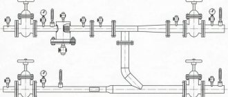
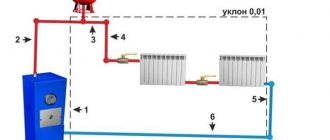
Connection diagram for distribution manifolds in a heating system
Installing a heating collector is the most effective and reliable option for a private home. However, the installation of this unit will be more expensive than the installation of a traditional tee system.
Manifolds for radiators and heated floors
The difference between a floor collector and a radiator collector is in the design associated with the difference in operating temperatures and the lower hydraulic resistance of the radiator elements. The design of the block for connecting underfloor heating is much more complex; it includes a large number of control water fittings and a circulation pump for multi-circuit systems.
The standard manifold block for household radiators has a simple design: it consists of supply and return manifolds of large cross-section, from which come fittings for connecting pipes going to the radiators. The device usually does not have any adjusting, tuning valves or other complex devices, so connecting and installing it does not cause difficulties for most homeowners. Heating radiators are connected to the unit through pipes running in the floor and connected from below at one point; to place a straight pipeline it is not necessary to make a screed; it can be laid in a groove cut or knocked out in the slab.
A typical collector block is a technically complex element with a large number of adjustments and settings; often a circular electric pump is installed in the system. When installing the block, you should distinguish between the forward and reverse feed combs; for convenience, they are marked with red and blue paints, respectively. Also, adjustable flow meters with a transparent cap and marked divisions indicating the volume of liquid passing through them are most often placed in a straight line; it is marked with an internal red indicator head.
Typically, the maximum value of the transmitted flow does not exceed 5 cubic meters per hour (corresponding to division 5 on the cap), the minimum mark is 0.5. If the indicator heads are in the upper part, then when the water flow passes through the supply comb, the indicator lowers and shows the volume of liquid passing through. Sometimes the heads are located at the bottom, in this case the flow moves in the opposite direction from the heating circuit to the comb and, accordingly, the flow meters are installed in the return flow bar.
If a circular electric pump is installed in the collector block, then its impeller directs the flow from the output comb to the supply housing - thus mixing cold water from the return line into the coolant heated by the boiler to lower its overall temperature.
The standard block provides space for the location of the thermostat sensor, there are exhaust valves for bleeding air in the supply and return combs, valves are installed in place of which there are seats for servos that perform automatic control of operating modes.
Rice. 11 Collector heating system for an individual house, Gidrostrelka - installation and connection diagram
- You might be interested in what the pressure in the heating system should be.
Advantages and disadvantages of a distribution manifold for a heating system
The collector version of the heating system has its positive and negative sides. Such a comb is capable of ensuring uniform heat distribution and maintaining the required coolant temperature in all heating devices. At the same time, it is possible to organize a decrease in temperature if necessary.
By adjusting the heating manifold, you can not only control the temperature, but also completely cut off any branch, which helps prevent idle heat transfer. This is especially convenient for a large house where some rooms are not used for living. The system is adjusted from the heating manifold cabinet.
The distribution manifold unit is characterized by ease of installation and repair. If one of the system parts breaks down, it will be enough to cut off the damaged branch using a control device. The heating comb has an attractive appearance, which allows you to place the device in any convenient place.
Installing a heating collector is the most effective and reliable option for a private home
The disadvantages of the hydraulic collector include the high cost of the design, which is associated with the high cost of the material from which the product is made. High-quality fittings are also quite expensive. However, the cost of installation work is kept to a minimum, which is due to the simplicity of the design.
The heating system will operate fully and efficiently only in conjunction with a circulation pump, the operation of which will entail additional energy costs.
The comb design involves a large number of branches for each heating device, for which a separate pipe is installed. This increases the complexity of installation and the total cost of the entire system.
Pipeline laying options
The main pipe laying schemes during installation are zigzag and spiral volute, the latter provides more uniform heating and is considered the best in efficiency. When laying pipes, a certain distance between sections must be maintained; it depends on the layout and thickness of the screed; its typical value for the usual thickness of the cement-sand layer is in the range of 150 - 200 mm.
The distribution manifold is the main unit in an individual heating system containing two or more underfloor heating circuits; it performs the functions of distributing and mixing the coolant to reduce its temperature. During installation, a pipeline made of cross-linked or heat-resistant polyethylene is placed under a screed in the form of a zigzag or snail and connected to the combs using Eurocones, which ensure a quick and tight connection.
Heating collectors: types of devices
There is no standard heating manifold configuration. The device can be made in any modification, which allows it to be adapted to a variety of heating systems with different types of devices and the number of circuits. The comb has from 2 to 12 circuits; the price of the heating collector depends on this indicator. During operation, the number of involved branches may vary.
The device can be made in any modification, which allows it to be adapted to a variety of heating systems
According to technical characteristics, heating distribution units can be divided into the following types of collectors: solar, with a hydraulic arrow and radiator. Based on the number of system elements, simple and advanced models are distinguished. The first option is not equipped with additional devices to control and adjust the operation of the device. It is represented by a simple comb with several branches, each of which can be turned off. In such a system, control over the temperature and volume of the coolant is not assumed.
Improved products are equipped with pressure and temperature regulators, pressure sensors, water supply control units, thermostats for automatic pressure adjustment, electronic mixers and valves for regulating the supply of cold and hot water, air vents for releasing air bubbles from pipes.
Important! The configuration of the collector unit may vary depending on certain system requirements, which affects the functionality and cost of the installation.
Flat or vacuum solar collectors for home heating
Solar collectors differ from traditional heating installations in their design. They consist of panels designed to convert solar energy into thermal energy. The absorber of a flat product is represented by an aluminum plate in which a copper coil is located. There is a natural circulation of coolant through it, which involves displacing the warm flow upward and directing it to the heating devices.
Solar collectors are placed on the roof of the house, where the maximum level of solar radiation is concentrated
It is advisable to use such systems in the southern regions. The devices are used to produce hot water, which can be used for centralized hot water supply or as a coolant for heating systems.
A vacuum collector for heating consists of light-absorbing flasks in which tubes are located where the coolant moves. This system is characterized by high efficiency. It can be installed even in regions with low levels of solar activity.
Solar collectors are placed on the roof of the house, where the maximum level of solar radiation is concentrated. Such systems do not take up much space and do not interfere with anyone.
Coolant circulation can be carried out naturally or forced. In the first case, the heated water expands and rises, and the cooled stream is forced into the heating tank. Forced circulation requires the presence of a pump. Using mixers, you can change the movement of water in the system.
A vacuum collector for heating consists of light-absorbing flasks in which tubes are located where the coolant moves
Solar collectors provide hot water to the house in the summer. In the spring-autumn period, such a system can be used as an alternative heating option, allowing to save gas or electricity consumption, thereby reducing the cost of paying for consumed resources.
Radiator water distribution manifold
The collector for radiator heating is the most popular, since batteries are installed in almost every house. The distribution unit is represented by two interconnected combs, where the first supplies the coolant to the heating devices, and the second removes the liquid back to the heater.
Such collectors can have a diagonal, top or bottom connection. The last option is the most common, since all the wiring is hidden under the surface of the floor or baseboard, which is not noticeable.
The radiator heating collector is installed on each floor of the house in a place that will ensure an equal length of supply branches to each heating device. The unit can be located in a niche or mounted in a special cabinet on the wall. The number of branches depends on the number of rooms that are looped on one comb. The number of collector groups should be based on the length of the circuits. 120 m of pipeline is allocated to one node.
A radiator heating collector is installed on each floor of the house
Important! If it is impossible to achieve equality of the connected rings to the collector, each outlet must be equipped with a circulation pump.
All branches connected to the node are independent circuits, equipped with their own shut-off valves and automation. Shut-off and control valves necessary for selecting the optimal coolant supply are installed here.
Characteristics of a distribution manifold with a hydraulic arrow
When arranging a heating distribution system with a large number of circuits, it is advisable to use manifolds with a hydraulic arrow, which is needed to balance the entire assembly. This is achieved due to the fact that the device separates the boiler hydraulic circuit from the secondary circuit. A heater is connected to a unit with a thermohydraulic distributor on one side, and a heated floor system or radiator heating on the other.
The hydraulic needle is represented by a vertical hollow pipe equipped with elliptical plugs at the ends. It helps equalize temperature and pressure, which guarantees optimal temperature between supply and return.
Effective operation of a heating system with a hydraulic arrow is possible if each circuit has its own circulation pump
Such a hydraulic separator allows, if necessary, to mix flows, compensate for the flow deficit in the secondary circuit, and maintain a constant volume of water. This is achieved through secondary circulation of some of the coolant. The hydraulic needle eliminates the possibility of sudden temperature changes in the pipes, which negatively affects the service life of the system.
Important! Optimal and efficient operation of a heating system with a hydraulic arrow is possible if each circuit has its own circulation pump.
Units with a hydraulic arrow are intended only for complex heating systems in large facilities. This is the most appropriate option for a heating distribution manifold with 4 circuits. In this case, it is possible to organize independent units with different operating parameters, such as hot water supply, radiator heating, heated floors, and heating water in the pool. Each of the 4 circuits on the heating manifold may differ in internal cross-section diameter, type of installed radiators or heating option.
Related article:
Do-it-yourself heating in a private house from polypropylene pipes
Classification, price and technical characteristics of PP pipes. Features of schemes and rules for installing water heating made of polypropylene.
If boiler room manifolds are used in a factory setting, they are equipped with special branches for air and debris, thereby increasing the efficiency of the entire system.
Units with hydraulic arrows are intended only for complex heating systems in large facilities
Factory manifold assembly
Let's first look at a specific example of what a ready-made distribution unit from the manufacturer consists of.
Table 1. Factory manifold assembly.
| Steps, photo | A comment |
| This collector assembly is called ready-made only because all the necessary elements, selected according to optimal parameters, have already been assembled. It itself is in a disassembled state, and all the parts still have to be put together. |
| This is a feed comb, each output of which is equipped with a flow meter (red device on top). Through it, the temperature range in the circuits is set. It is on this comb that, if necessary, the coolant supply to the circuits is shut off. |
| The return comb, unlike the feed comb, is equipped with push-action thermostatic shut-off valves. They are covered on top with caps, on the front side of which the direction of rotation (plus and minus) is indicated, by turning which you can adjust the feed manually. |
| Instead of a cap, you can install a servo drive on the valve, which will automatically regulate water flows. These devices are not included in the kit, but are purchased separately. |
| The desired temperature is set on the thermostat, and it already sends a signal to the servo drive. |
| The heating system is turned off using taps. |
| At the end of each collector, units are installed through which you can drain water from the system or bleed air. |
| We think there is no need to explain the purpose of the thermometer. |
| On the left side of the supply comb there is a hole through which heated water flows from the boiler. First, a tee with a thermometer is screwed onto it, and then a ball valve, through which the connection to the pipeline will be made. The same is done on the return line. |
| To the right, drain units are screwed onto both combs. |
| The manifold assembly kit includes a bracket, through which both combs are tied together and then hung on the wall. |
| The assembled unit is attached to the wall or installed in a special cabinet. |
| All that remains is to connect the supply pipeline and circuits to the manifold. |
Video - Manifold for underfloor heating and heating. Review, assembly and installation of the STOUT manifold block
Features of the water distribution manifold comb
To increase the comfort of using hot and cold water, sanitary manifolds with shut-off valves are used. The device ensures the division of water into several streams. Due to the fact that the diameter of the inlet opening exceeds this value for the outlet pipe by 20-40%, when several taps are opened simultaneously, a decrease in water flow and pressure does not occur.
The collector circuit is more convenient and comfortable to use than the traditional one. However, its cost will be several times higher than the price of a conventional system. For example, a Pexay water distribution manifold costs 5-10 thousand rubles.
Manifolds are made of stainless steel, brass, polypropylene or cross-linked polyethylene. Pipes for the water supply system can be fastened using threaded connections, using Eurocones, using compression fittings. A combined version is also used, which involves threaded connections for large diameters and soldering or compression fittings for small ones.
Distribution manifolds for water supply can be equipped with 2-6 outlets. The product has two attachments for docking, which correspond to the diameter of the pipe supplying water. They are also used to connect several elements into a composite unit without the use of additional adapters.
To increase the comfort of using hot and cold water, manifolds with shut-off valves are used
Important! The collector water supply system allows you to turn off one of the water consumers in order to carry out repair and restoration work without affecting the others.
When choosing a material for making a manifold, the type of supply pipe should be taken into account. It is better if they are made of the same material. Here it should be taken into account that polyethylene products are connected with compression fittings, and polypropylene products are connected by soldering. A filter, metering device and check valve should be installed in front of the collector.
Helpful advice! To facilitate installation work and ensure reliable connection of elements, it is necessary that the water supply manifold, pipes and fittings be manufactured by the same manufacturer.
Feed and return manifold comb device
Combs are one of the main elements of the collector circuit; their main function is to distribute the coolant flow along the heating circuits. The element has a different design for lines of connected radiators and heated floors, the maximum number of involved circuits per collector does not exceed 12.
In relation to the diameters of the outlet fittings, the comb has a large cross-section (1.1 1/2 inches versus 3/4) and is connected to the main line through an end connection with elements of plumbing fittings. Typically, the pipeline is connected to the outlet fittings using compression fittings (Eurocones) - this method can be used to connect pipes made of cross-linked and heat-resistant polyethylene, metal-plastic, most often used in manifold heating systems. Combs are made of stainless steel, brass, plastic, some modifications are assembled from individual links.
Materials for the production of distribution manifold combs for heating
Different materials can be used to make a heating manifold, but they must be characterized by increased strength and high performance characteristics.
The main disadvantage of steel collector elements is their high cost.
Currently, steel, polymer and brass manifolds are very popular. Steel can be used for the production of both central and local elements. It does not deform under the influence of high temperatures and high pressure; special alloys are not subject to corrosion, which increases their service life. The main disadvantage of steel elements is the high price of heating collectors.
Brass devices are no less in demand. Due to the fact that the material can withstand high pressure and temperature, it is ideal for local and centralized units. In terms of its technical and operational characteristics, it is similar to stainless steel. Brass manifolds are characterized by a high cost, exceeding the price of steel analogues.
Polymer products have a more limited range of applications. Plastic collectors are not able to withstand high temperatures in the central unit, therefore they can only be used for local options, where the coolant temperature will be lower. The products are characterized by light weight, ease of installation and long service life. The main advantage of the products is their low cost.
Important! Polymer pipes should not be used to connect a heated floor system.
Currently, steel, polymer and brass manifolds are very popular
Basic recommendations for choosing a heating collector
Before purchasing a heating manifold, you should study the technical characteristics of the devices, which include the throughput of the system, the maximum operating pressure of the product, the possibility of connecting additional circuits, the availability of control and automation equipment, and the amount of electricity consumed. These parameters are indicated in the device passport.
Important! The pressure in the distribution system will depend on the location of the manifold.
When choosing a collector for radiator heating or a heated floor system, it should be taken into account that a high-quality and durable device will have a high cost. This is due to the fact that durable, expensive materials are used for its manufacture, and the production technology is carried out using the latest, improved equipment. A guarantee of quality is the purchase of a manifold from a well-known manufacturer with a worldwide reputation.
A simple system can be installed independently, but it is better to entrust the installation of an advanced type heating collector to a specialist. This is especially true for a distribution unit with 3-4 circuits. The collector system will be able to fully function if there are taps, plugs and a circulation pump for each circuit, which will increase the cost of the system.
You can install a simple system yourself, but it is better to entrust the installation of an advanced type heating collector to a specialist
Pipe selection
Although pipelines made of various materials can be used to supply water and install circuits, in everyday life they mainly use polymers, which are supplied in coils of various lengths and are easily bent when laying loops.
The main materials of heating pipelines are: metal-plastic made of cross-linked polyethylene PEX with an aluminum layer between the inner and outer shells, cross-linked PEX and heat-resistant PE-RT polyethylene.
It should be noted that metal plastic is not very practical as a material for heated floors - due to its high rigidity, it is difficult to bend with a small radius, and mechanical impact on the surface during installation or before laying the screed leads to bends and breaks. You can repair a metal-plastic pipeline by inserting a section connected using compression or crimp fittings - this leads to a decrease in the passage channel and an increase in hydraulic resistance.
Pipes made of cross-linked and heat-resistant polyethylene have the same service life of about 50 years; it is believed that the PE-RT pipeline is easier to install in rooms with low temperatures, and if damaged, it can be easily repaired by soldering, although the technology is not very well known. Also, the cost of PE-RT is lower than cross-linked polyethylene PEX, although there are enough products of both categories at a relatively low price on the construction market.
Rice. 19 Basic pipe laying schemes for heated floors
Choosing a location for installing the heating collector
Before connecting the heating collector, check the installation location for any interference. Such a distribution heating system involves floor-by-floor installation of pipelines. An independent heating circuit with autonomous control is organized for each floor. In this case, the parameters of the subsystem they serve are taken into account.
The unit is installed in a separate niche just above the floor. The location of the device is selected at the design stage of the house. If this was not provided, then the collector can be placed anywhere by hiding it in a closet. The main requirement is the optimal humidity of the room where the heating distribution unit will be located. A closet, corridor or dressing room is suitable for this purpose.
You can make a cabinet for a distribution unit yourself or purchase it ready-made from a manufacturer that produces shut-off valves. The design is represented by a metal box with doors. The end walls of the product have holes for laying system pipelines.
If there are no aesthetic requirements for the installation location of the collector, then it can be attached to the wall in an open form using special clamps.
You can make a cabinet for the distribution unit yourself or purchase it ready-made
Installation and connection rules
It is best to select and install a collector at the stage of design and installation of the heating system.
Such intermediate structures are installed in rooms protected from excess humidity. Most often, space is allocated for these purposes in the hallway, pantry or dressing room.
It is advisable to place the collector block in a metal cabinet specially designed for this purpose, equipped with holes in the side walls for pipe outlets
On sale there are overhead and built-in models of metal cabinets. Each model is equipped with a door and stampings on the sides.
In the absence of the opportunity to install a metal cabinet, it is easier to do it by fixing the device directly to the wall. The niche for arranging the collector block is placed at a low height relative to the floor.
There are essentially no generally accepted instructions for installing collector distribution circuits. But there are a number of main points regarding which experts have come to a common denominator:
- Availability of expansion tank . The volume of the structural element must be at least 10% of the total amount of water in the system.
- The presence of a circulation pump for each laid circuit . Regarding this element, not all experts are unanimous in their opinion. But still, if you plan to use several independent circuits, it is worth installing a separate unit for each of them.
An expansion tank is placed in front of the circulation pump on the return line. Thanks to this, it becomes less vulnerable to the turbulence of water flows that often occur in this place.
If a hydraulic arrow is used, the tank is mounted in front of the main pump, the main task of which is to ensure circulation in the small circuit.
The location of the circulation pump is not important. But, as practice shows, the service life of the device is somewhat higher on the “return” route.
The main thing during installation is to position the shaft strictly horizontally. If this condition is not met, the very first bubble of accumulated air will leave the unit without cooling and lubrication.
The process of assembling and connecting the collector system is clearly presented in the video block.
Popular manufacturers of heating system manifolds
Popular manufacturers of high-quality collectors are the companies Rehau and Oventrop, which provide the maximum warranty period for their products. Consumers note the high quality of products, reliability, ease of installation and long service life.
Oventrop specializes in the production of universal manifold models that are ideal for radial heating, underfloor heating and water supply systems. High-quality stainless steel is used to manufacture products. The collectors can withstand temperatures up to 120 °C. The cost of products varies from 2.5 to 28 thousand rubles.
The most popular among consumers are radial heating combs made of stainless steel. Such collectors are designed for a pressure of 10 bar and a system temperature of up to 100 °C. You can buy the product for 1.7 thousand rubles. Distribution manifolds for underfloor heating made of tool steel are produced with valve accessories, with the help of which the operation of the system is regulated. The manifolds are designed for pressures of 6 bar and temperatures up to 70 °C. You can buy a double-circuit product for 3.5 thousand rubles.
Rehau distribution manifolds have a more attractive appearance, which makes it possible to mount them on the wall in an open manner. Products are made of stainless steel and brass. The company produces improved models equipped with flow meters, taps, valves and a pump. You can purchase the device for 1.5-32 thousand rubles, which depends on the number of circuits of the product.
Rehau distribution manifolds are not only very reliable, but also have an attractive appearance
The HKV comb for underfloor heating systems, made of brass, is very popular. The manifold is designed for temperatures up to 80 °C and operating pressure up to 6 bar. The cost of a double-circuit product is 6.5 thousand rubles.
The Rehau HLV distribution manifold can be used for radial heating. The brass product can withstand temperatures of 80 °C and pressure of 8 bar. The price of the model is 4 thousand rubles.
The domestic manufacturer North deserves attention, offering high-quality hydraulic manifolds at an affordable price, which varies between 2.5-20 thousand rubles. Products are made primarily of steel. Pexay heating collectors are characterized by an ideal price-quality ratio, the price of which averages 5-12 thousand rubles.
Finally about homemade collectors
Above in the text we mentioned budget options for combs - tap, polypropylene and homemade. Such distributors can be used without problems in radiator beam circuits. To balance and regulate the flow, a balance valve and a faucet with a thermal head are installed on each battery. The collector is equipped with “air vents” + drain taps.
If you put the indicated combs on the TP, you will encounter the following nuances:
- the distributor cannot be equipped with rotameters;
- without flow meters it is difficult to balance circuits of different lengths;
- Factory plastic manifolds have shut-off valves, which means there is nothing to regulate the flow;
- combs assembled from polypropylene or brass tees have many joints;
- It's worth noting that homemade distributors don't look too good.
A self-made underfloor heating manifold can still be brought to perfection. We assemble the distributor from tees, and on the return connections we mount thermostatic radiator valves with RTL-type thermal heads, as shown in the photo.
A skilled owner can easily make a coplanar common house collector - weld it from a round or profile pipe. But there’s a catch in the calculations: you need to know the cross-section of the chambers and pipes for a specific heating system. If a specialist calculates these parameters, use the experience of the master from the video:
