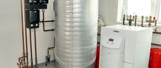
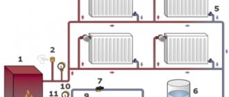
When operating heating systems with natural coolant circulation, owners of apartments and private houses are often faced with the problem of insufficient heating of radiators installed in remote rooms.
It all depends on the length of the heating circuit. If its length is more than 30 meters, the level of water pressure becomes insufficient to maintain the required temperature at its most distant points.
To achieve stable operation of the equipment, devices are used that ensure rhythmic circulation of the coolant. Preliminary calculation of a pump for a heating system makes it possible to determine the parameters necessary to select the most optimal model.
Why are calculations needed?
Most modern autonomous heating systems, used to maintain a certain temperature in residential premises, are equipped with centrifugal pumps that ensure uninterrupted circulation of liquid in the heating circuit.
By increasing the pressure in the system, it is possible to reduce the temperature of the water at the outlet of the heating boiler, thereby reducing the daily consumption of gas consumed by it.
The correct choice of the circulation pump model allows you to significantly increase the level of equipment efficiency during the heating season and ensure a comfortable temperature in rooms of any size.
Which one is better to choose?
Before choosing a water pump for your home, you should compare the advantages and disadvantages of their two main types:
| Surface pumps | Submersible |
| Installed permanently. Easier to maintain. | For repair and maintenance work, they require lifting from a well or well to the surface. |
| They need two pipelines: suction and discharge. | They work only for injection. |
| The maximum suction height is 10 m. The real one, taking into account losses in the pipeline and the reserve for lowering the water level in the well, is no more than 7~8 m. | Ascent from depths below 10 m. |
| They need to be filled with liquid before the first start-up or after repair work. | Ready to go immediately after diving. |
| There is a danger of the motor overheating during prolonged operation. | A pump immersed in water is cooled both by external water from the outside and pumped from the inside. |
| The need for winter preservation for the summer version of the water supply system. | For the winter, it is enough to drain the water from the system. |
| Work is accompanied by noise. | Silent. |
Thus, to lift water from a well it is easier to use a surface pump or pumping station, and from a well - a submersible rotary or centrifugal one.
What you need to know to calculate power
To understand the algorithm for calculating a circular pump, it is necessary to start from some parameter, the accuracy of which cannot be doubted. To do this, you need to open the technical passport of the room in which you plan to install an autonomous heating system and find out its area. For example, let’s take a separate building (private house) with an area of 300 m².
The next step is to determine the quantities needed for the calculation.
You need to know three main parameters:
- Qn —heat source power (kW);
- Qpu is the performance of the circulation pump, an indicator of the volumetric supply of coolant for the type of room we have chosen (m³/hour);
- Hpu is the pressure power required to overcome the hydraulic resistance of the system (m).
Calculation of heat source power (AOGV)
For each room, depending on its area or volume, there are certain technical standards for the power of the heating source.
To calculate this parameter we use the following formula:
Qn = Sn × Qsp ÷ 1000
| Designation | Parameter | Units |
| Qn | heat source power | kW |
| Sn | heated area | m² |
| Qsp | specific heat demand of the room | W/m² |
We know the area of the heated room (300 m²), and the second indicator depends on the type of structure: if it is an apartment building, then its value is 70 W/m², in our case (a separate building), it will be 100 W/m².
Let's plug these values into the formula and see what we get:
300 × 100 ÷ 1000 = 30 kW.
So, the power of the heating unit for our room was 30 kW. There is another method for determining this value.
The volume of the heated room and the power of the heating unit can be found in the following table.
| Thermal power | Room volume new house (m³) | Room volume old house (m³) |
| 5 kW | 70 – 150 | 60 – 110 |
| 10 kW | 150 – 300 | 130 – 220 |
| 20 kW | 320 – 600 | 240 – 440 |
| 30 kW | 650 – 1000 | 460 – 650 |
| 40 kW | 1050 – 1300 | 650 – 890 |
| 50 kW | 1350 – 1600 | 900 – 1100 |
| 60 kW | 1650 – 2000 | 1150 – 1350 |
Let me remind you that the volume of a room is equal to the product of its area and height.
(V = S × h), where:
- V is the volume of the room;
- S - heated area;
- h is the height of the rooms.
In our case, with a ceiling height of 2.5 m, it will be:
300 × 2.5 = 750 m³
We look for this indicator in the second column of the table and get the same 30 kW.
Calculation of pump performance
Correct calculation of pump power allows you to provide the heating system with the required amount of coolant at any point. Having determined the technical characteristics of the heating boiler, we can calculate the performance of the circulation equipment sufficient for our premises.
Let's use the following formula:
Qpu = Qn ÷ kτ × Δt
| Designation | Parameter | Units |
| Qpu | pump performance | m³/hour |
| Qn | heat source power (AOGV) | kW |
| kτ | liquid heat capacity coefficient | — |
| Δt | temperature difference at the system inlet and outlet | ⁰С |
If water is used as a coolant, its specific heat capacity is 1.164. If a different liquid is used, then the value of this parameter must be looked up in the corresponding tables.
With a functioning heating system, the value of the temperature difference (Δt) can be calculated by the method of elementary subtraction of indicators taken from measuring instruments installed at the input and output of the system (Δt = t1 – t2, where t1 is the temperature at the inlet of the heating circuit, and t2 is the temperature at the outlet from him).
Otherwise, you will have to use standard indicators. The temperature difference at the inlet and outlet of the system (Δt) ranges from 10-20 ⁰С.
Let's take the average value - 15 ⁰С and substitute the results obtained into the formula:
Qpu = 30 ÷ 1.163 × 15 = 1.72 m³/hour
Now one of the technical characteristics of the circulation pump is known.
Calculation of the required power (height) of pressure
The power of the heating boiler and the performance of the pump are known; the next step is to determine the coolant pressure sufficient to overcome the internal hydraulic resistance of the pipes and elements of the heating system.
To do this, the heat losses on the longest section of the circuit are taken into account - from the heat source to the distant radiator. To deliver heat to any point, the pressure power of the supplied liquid must be higher than the total hydraulic resistance of all heating devices.
The heating pump pressure is calculated using the following formula:
Hpu = R × L × ZF ÷ 10000
| Designation | Parameter | Units |
| Hpu | Power (height) of pressure | m |
| R | Losses in supply and return pipes | Pa/m |
| L | Heating circuit length | m |
| ZF | hydraulic coefficient resistance of shaped and shut-off valves of the system | — |
Depending on the diameter of the pipes, the value of the parameter R is in the range of 50–150 Pa/m (the minimum value is applicable for water supply systems with a pipe diameter of 2 inches and above; for modern plastic and metal pipes the losses are 150 Pa/m). For our premises it is necessary to use the maximum value.
If the exact length of the circuit (L) is difficult to determine, this parameter is calculated based on the dimensions of the heated room. The length, width and height of the house are added and then doubled. With a total area of 300 m², we can assume that the length of the house is 30 m, the width is 10 m, and the height is 2.5 m. In this case, L = (30 + 10 + 2.5) × 2, that is, 85 meters.
The simplest option for determining the ZF value is as follows: if there is no thermostatic valve in the system, it is equal to 1.3, and if it is present, it is 2.2.
To calculate, take the maximum value of this coefficient and substitute all the obtained values into the formula:
150 × 85 × 2.2 ÷ 10000 = 2.8 m.
The proposed calculation method is not the only one. To more accurately determine the pressure indicators of the pump, there are formulas that take into account not the loss coefficient, but the real values of these indicators.
Hydraulic resistance
This term expresses the total pressure loss in the system. The heating circuit consists of individual elements, each of which has its own value for this characteristic.
These include:
- valves;
- valves;
- filters;
- measuring and control instruments;
- radiators;
- convectors, etc.
To accurately determine losses in the system, the values specified in the technical documentation for each component of the heating circuit are usually used.
If this is not possible, you can find this information in the following table:
| System element | Pressure loss | Units |
| Boiler | 1000 – 5000 | Pa |
| Compact boiler | 5000 – 15000 | Pa |
| Heat exchanger | 10000 – 20000 | Pa |
| Heat meter | 15000 – 20000 | Pa |
| Water heater | 2000 – 10000 | Pa |
| Heat pump | 10000 – 20000 | Pa |
| Radiator | 500 | Pa |
| Convector | 2000 – 20000 | Pa |
| Radiator valve | 10000 | Pa |
| Control valve | 10000 – 20000 | Pa |
| Check valve | 5000 – 10000 | Pa |
| Filter (clean) | 15000 – 20000 | Pa |
| Thermostatic valve | 5000 – 10000 | Pa |
| Mixer | 2000 — 4000 | Pa |
In this case, to calculate the head height it is convenient to use a slightly different formula.
H = 1.3 × (R1L1 + R2L2 + Z1 + Z2 + .... + Zn) ÷ 10000, where:
- R1, R2 – losses in the supply and return pipes (Pa/m);
- L1, L2 – length of supply and return pipeline lines (m);
- Z1, Z2 ... Zn – pressure loss on individual elements of the system (Pa).
The number in the denominator of the formula (10000) is the conversion factor from Pascals to meters.
Choosing a pump
Once all the necessary parameters for purchasing a circulation pump have been determined, you can begin to select a specific model. The technical characteristics of devices of this type are reflected in the graphs of the relationship between device performance and pressure height, attached to their passport. This data can be easily found on the Internet.
Depending on the number of velocities in the coordinate system, one, two or three graphs are constructed indicating the point of the optimal relationship between these quantities. We plot the pump performance value on the X axis, and the height of its pressure on the Y axis. The intersection point of these parameters should be as close as possible to the point indicated on the graph - their complete combination would be ideal.
The most common models have a three-speed operating mode. If you choose one of them, then the selection of characteristics must be carried out according to the schedule corresponding to the second speed, that is, the average. In other cases, the parameters are combined using any of them.
Prices for different models of pumps for the heating system
heating pump
Wilo performance and quality
The Wilo heating circulation pump, which can be increasingly found in modern heating systems, is designed to maintain a high level of coolant circulation in the network.
Thanks to its operation, consumers receive much more thermal energy. In addition, this leads to an increase in the efficiency of the entire system. The inclusion of a Wilo circulation pump in the circuit allows for a noticeable reduction in pipe consumption. The fact is that in this case, pipes of a much smaller diameter are used for the system, in contrast to systems based on the principle of natural circulation.
During operation, Wilo pumping units are almost completely silent. At the same time, they are distinguished by high reliability and practicality, small dimensions, without creating problems during maintenance. They can be installed very quickly.
Each circulation pump that Wilo offers has such qualities as modern design, high performance, and a long service life.
It is also important that the installation procedure of these devices does not require much time and effort. The price of this equipment is also quite attractive, in which many competitors are inferior to it.
Today on sale you can find many models of pumps manufactured by this famous German concern. Many websites have already been created that provide anyone with the opportunity to get acquainted with the Wilo product range, which is distinguished by its great variety.
Varieties
Although the Vilo company has managed to produce a lot of circulation pumps, the following models, which are easy to install, can still be considered highly in demand:
- WiloStar-RS and WiloStar-RSD model - although they do not have impressive power, this is compensated by high reliability, as well as a low price. They can be connected to many home heating systems. These devices are equipped with a manual speed switch, with which you can increase the efficiency of the device. Such pumps can be installed in rooms with an area of 200-750 square meters. m;
- Wilo Stratos ECO - these samples are an improved version of the previous generation of circulation pumps. They can operate as part of large heating systems, to which a boiler with a capacity of at least 25 kW is connected. These models are characterized by the presence of electronic control, which allows you to select the desired power and performance mode. These samples can successfully heat small cottages. Among the advantages that such pumping units have are low electricity consumption, as well as the ability to perform their functions even in conditions of subzero temperatures;
- TOP-RL and model TOP-S - the main purpose of these pumps is to heat objects with a minimum area of 1400 square meters. m. Models are presented in three-phase and dual versions and provide the possibility of transferring to modes of increased efficiency and productivity;
- Wilo TOP-Z - the uniqueness of these units is that they can be used in systems in which there is a possibility of the formation of deposits of magnesium and calcium salts. Demonstrating high operational efficiency, these devices do not fail even when low-quality water is supplied to the system.
Pump advantages
With many advantages, circulation pumps for heating systems from Wilo are also distinguished by their versatility. Plus they are easy to install. Therefore, this option for solving the heating problem is suitable for both owners of small country houses and owners of industrial enterprises.
By giving preference to pumps of this brand, the buyer can count on the following advantages:
- Thanks to more efficient circulation through pipelines, the amount of supplied thermal energy increases, which easily reaches the most remote areas of the heating system;
- Boilers start working with less fuel consumption, which saves money. First of all, this positive effect is felt when using circulation pumps in large boiler rooms at manufacturing enterprises and other facilities;
- The decision to equip the heating system with a circulation pump has a positive effect on the service life of the system. The use of such installations makes it possible to maintain a high level of pressure in the system, which prevents the formation of salt deposits while the coolant moves through the pipes. Another advantage of these units is the absence of blockages and narrowing of pipe diameters.
How to calculate a pump if the boiler power is known
Situations often arise when a boiler is purchased in advance or a pump is added to an already functioning heating system. In this case, the power of the heating unit is known, and all other elements of the circuit are selected depending on the value of this indicator.
To calculate the performance of the circulation pump at a given power of the heating source, use the following formula.
Q = N ÷ (t2 - t1), where:
- Q – pump capacity (m³/hour);
- N – power of the heating device (W);
- t2 – coolant temperature at the system inlet (⁰С);
- t1 – liquid temperature at the outlet of the circuit (⁰С).
If it is not possible to accurately determine the specified supply and return parameters, use the average temperature difference - 15 ⁰C.
Resistance
In addition to the need to push water to a certain height, the pump must be able to overcome the resistance created in the pipeline. A pipe that is too narrow will increase resistance and system performance will decrease, while a pipe that is too wide will require unnecessary costs. The diameter of the water conduit should be optimally selected to avoid unnecessary resistance.
To calculate the resistance, check out the pressure loss graph for a pipe of a specific type and diameter: this way you can calculate the losses for a certain volume of water. If there is no graph or you don’t want to count, use the simple recommendation below:
Recommended HDPE pipe diameter:
- flow up to 1.5 m3/hour – 25 mm
- flow up to 3 m3/hour – 32 mm
Number of pump speeds
By its design, a circulation pump is an electric motor mechanically connected to the shaft of an impeller, the blades of which push the heated liquid out of the working chamber into the heating circuit line.
Depending on the degree of contact with the coolant, pumps are divided into devices with a dry and wet rotor. In the former, only the lower part of the impeller is immersed in water, while in the latter, the entire flow passes through itself.
Models with a dry rotor have a higher coefficient of performance (efficiency), but create a number of inconveniences due to noise during operation. Their analogues with a wet rotor are more comfortable to use, but have lower performance.
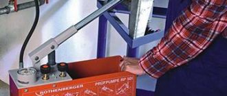
Modern circulation pumps can be operated in two or three speed modes, maintaining different pressures in the heating system. Using this option makes it possible to quickly warm up the room at maximum speed, and then select the optimal operating mode and reduce the energy consumption of the device by up to 50%.
Speed switching is carried out using a special lever mounted on the pump body. Some models have an automatic control system that changes the engine speed in accordance with the air temperature in the heated room.
Submersible centrifugal electric pumps
Introduction
submersible centrifugal electric pump
Submersible centrifugal electric pumps are designed for pumping liquid, water, oil, mechanical and chemical impurities from oil wells, including directional ones, and are most suitable for operating oil wells with high flow rates.
The centrifugal pump is lowered into the well under the liquid level on the tubing pipes and is driven by an electric motor located underneath it, the electricity to which is supplied through a special cable. The location of the drive motor directly next to the pump allows it to transmit high power.
Maintenance of borehole centrifugal pumps is simplified due to the fact that only the control station and transformer are located on the surface. Installation of the equipment is also simplified, since the relatively lightweight control stations and transformer do not require a foundation.
The service life between well centrifugal pumps for medium and large extractions is longer than for sucker rod pumps.
Downhole centrifugal pumps are designed to lift liquid with a water content of no more than 99%, mechanical impurities (by weight) of no more than 0.01%, with a temperature of no more than 90 °C. Pumps with increased wear resistance allow a content of mechanical impurities (by weight) of up to 0.05%. To lift highly corrosive liquids from an oil well, downhole centrifugal pumps are used, the main parts of which are made of corrosion-resistant materials.
1.Analysis of existing structures
The installation of a submersible centrifugal electric pump (ESP) is an oil well, Figure 1.1, into which a submersible pumping unit, consisting of a multistage centrifugal pump 2 and a submersible electric motor 1, is lowered on a tubing string 4 (tubing) under the liquid level, consisting of a multistage centrifugal pump 2 and a submersible electric motor 1. Electricity to the submersible electric motor 1 is supplied via armored cable 3, secured externally to the tubing column with special clamps. On the surface of the earth, the cable is connected to the autotransformer 8 and the control station 7.
The well production is lifted inside the tubing string 4 as a result of the operation of a submersible centrifugal electric pump, which is driven by a submersible electric motor. The tubing is suspended in the well using wellhead equipment 6, which has a special seal design that ensures sealing of the cable at the point of its entry into the well.
Electricity is supplied through a cable from the surface to a submersible electric motor, where it is converted into mechanical energy of rotation of the motor shaft. The motor shaft drives the shaft of a submersible pump, connected into a single assembly structure with a submersible electric motor. As a result, the pump takes fluid from the well and injects it under pressure inside the tubing string and then through the wellhead equipment into the onshore pipeline.
Figure 1.1 — Installation of a submersible centrifugal electric pump of the ESP type:
1 — electric motor with hydraulic protection; 2 - pump; 3 - cable line; 4 - tubing string; 5 — fastening belt; 6 - wellhead equipment; 7 - control station; 8 - transformer
1.1 Domestic ESPs
The domestic industry envisages the production of pumping units of conventional (ECSP) and modular (ECSP) versions.
A submersible centrifugal pump (ECP) for oil production is a high-pressure multistage vertical pump designed to operate by submerging it under the level of the produced fluid in the well. Pumps produced for the oil industry contain from 130 to 415 stages, located inside section bodies connected to each other via flange connections. Pumps are available in two-, three- and four-section designs. The sections are divided into “lower” and “upper” sections and are structurally not interchangeable.
Section length up to 8300 mm. The outer diameter of the body of all assembled sections is the same and depends on the cross-section of the well. In accordance with this, conditional groups 5, 5A, 6 were formed. Group 5-92 mm, group 5A - 103 mm, group 6-114 mm. For each group of pumps, pump sizes have been developed, Table 1.2. The upper section of the pump has a fishing head for threaded connection with the tubing string, and a lower flange for connection with the upper section, and in the lower receiving device (base), protected by a mesh for sampling the produced fluid.
Useful tips
When choosing a pump for a heating system, preference should be given to designs with a “wet” rotor, since they operate very quietly and withstand higher loads than hydraulic devices of other modifications.
In addition, pay attention to the material of the case - opt for products made of stainless steel, bronze or brass. Preference should also be given to models with bearings and shafts made of ceramics. The service life of such equipment exceeds 20 years.
When installing the device into the system, it is necessary to ensure that the impeller shaft is positioned horizontally, that is, parallel to the pipe. If a suspicious noise appears during operation of the pump, this does not indicate a malfunction or a manufacturing defect. Try bleeding the air remaining in the system after starting.
Well
For each pump model, the permissible values of foreign inclusions in the water (sand, etc.) are established. Failure to comply with the requirements leads to rapid wear and tear of the device and will void the warranty. Therefore, before selecting or buying a well pump, it is necessary to pump the well and do a water analysis.
A well is a round deep hole of small diameter with a pipe inside forming the walls. At a certain height, the pipe walls have holes, the so-called filter. There is a column of water in the well.
Before choosing a pump, find out:
• Static water level • Dynamic water level • Well flow rate
These characteristics play a key role when choosing a well pump. It is necessary to determine at what depth the water mirror, or that same static level, is located. It is called so because the water at the moment of measurement is in a calm position.
When the pump is turned on, the static level will decrease to the dynamic level: the water cannot fall below the dynamic level. The difference between the statistical and dynamic volumes of a well is called flow rate.
Important: the pump should not pump out more than the well can produce. Thus, a pump power of 3 m3/hour is absolutely not suitable for a well with a flow rate of 1.5 m3
Ideally, the pump should be slightly weaker than the well flow rate, by about 20-30%.
Find out at what depth the well filter is located. The pump should be positioned 1 m below the dynamic water level and 1 meter above the well filter. This data is usually indicated in the well passport.
So
• Static level – depth of the water surface at rest; • Dynamic level – minimum depth of the water surface; • Flow rate – volume of water (measured in liters per minute or cubic meters per hour)
Design differences
Hydraulic pumps come in the following design types:
Conclusion
• Pressure is calculated in meters: 10 m water column = 1 bar. • Flow is measured in m3/hour (less often - l/min). • The pressure-flow characteristic is a graph that allows you to determine whether a pump is suitable for a particular well. • Well: static water level – depth of the water surface in a calm state; dynamic level - the depth below which water theoretically cannot fall; flow rate is the volume of water that a well can produce per hour. • Pipe: use the maximum permissible pipe diameter to reduce resistance • Observe the maximum and minimum pump immersion depth requirements.
Following these recommendations will allow you to independently select a well pump that is optimally suitable for inclusion in the system.
The concept of expense. Flow Characteristics
CONCEPT OF CONSUMPTION:
Flow is the amount of liquid, gas or steam passing per unit time through the cross section of a pipeline or channel. In this case, the amount of medium measured in volume units is called volumetric flow , and in mass units - mass.
Volume flow is determined by the formula:
where Q is volume flow; V—flow velocity; S is the cross-sectional area of the flow.
Mass flow is determined through density and volume flow:
where Qm is mass flow; ρ is the density of the measured medium.
As a rule, the following volumetric units for measuring the amount of medium are used: liter (l), cubic centimeter (cm³) and cubic meter (m³); and mass ones - gram (g), kilogram (kg) and ton (t).
FLOW CHARACTERISTICS:
The most important characteristics of the flow that influence the nature of the movement of the medium are:
- flow rate;
- density of the measured medium;
- viscosity of the measured medium.
Viscosity (dynamic) is a physical property of a fluid that characterizes internal friction between its layers. The unit of measurement for viscosity is Poise (P); the viscosity of low-viscosity liquids and gases is measured in hundredths of Poise - centipoise (cP).
Along with dynamic viscosity, a quantity called kinematic viscosity :
where ν is kinematic viscosity; µ—viscosity.
The unit of measurement of kinematic viscosity is Stokes (St), in practice its hundredth part is more often used - centistokes (cST).
The viscosity of liquid media decreases with increasing temperature, and this dependence is different for different liquids. At the same time, the viscosity of liquid media also depends on pressure, usually increasing as it increases. However, at pressures encountered in most cases (up to 20 MPa), this change is insignificant and, as a rule, is not taken into account.
For gaseous media, the dependence of viscosity on pressure and temperature is very significant: with increasing pressure, the kinematic viscosity of gases decreases, and with increasing temperature it increases.
MOVEMENT OF LIQUID IN THE PIPELINE:
The flow rate, viscosity and density of the liquid determine the mode of movement of the liquid in the pipeline. The study of the mechanism of media movement led to the conclusion that there are two modes of fluid movement:
- laminar mode of motion is observed at low speeds, when individual layers of the medium move parallel to each other without mixing particles;
- The turbulent mode of motion is observed at high flow velocities and is characterized by intense mixing of particles.
The criterion for evaluating both modes is the Reynolds number:
Re = (V • D • ρ)/µ = (V • D)/ν,
where Re is the Reynolds number; D is the internal diameter of the pipeline.
Briefly about the main thing
The pump pressure is measured in meters, as this is customary, convenient and practical, and determines the height to which water can be raised through the pipeline. To perform a simple head calculation, the following number of factors must be taken into account:
- The difference between a vertical and horizontal section of a water pipeline.
- Required pressure at the receiving point.
- Formula for calculating the pressure at the entrance to the water supply of a house.
- Factors determining pressure loss in a pipeline.
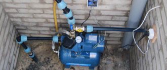
In everyday life, centrifugal, surface and submersible pumps are used to organize water supply for a private home. Each of them has its own nuances for calculating the pressure characteristics. Improper installation of pipelines and equipment can also lead to deterioration in pressure.
The influence of installation on the pressure value
When installing a pump, the following series of errors are often made, which directly or indirectly affect the reduction in pressure:
- Mismatch between the diameters of the suction pipe and water supply . Often, when organizing a water supply system, pipes are selected in such a way that a significant difference arises between the internal diameter of the water supply pipe and the suction pipe of the pumping unit, which naturally cannot but negatively affect the pressure and pressure of water at the points of consumption.
- Connect directly to the hose . Low-performance models can be used in this form. However, even average household analogues will experience a significant reduction in performance indicators. Because under pressure the elastic material will simply shrink. As a result, the supply will either decrease significantly or stop altogether.