The pump power should be selected based on the tasks for which it will be intended. The pump power that is supplied to the shaft is called input power. It is defined as the sum of the torque on the shaft of the device to its angular velocity. In the process of selecting a unit, it is important to take into account the following indicators: pressure and flow rate, pump coefficient (efficiency), cavitation, etc. The selected pump must operate with the highest efficiency, without cavitation, in the required pressure and flow range.
How to find out the pump flow rate
The calculation formula looks like this: Q=0.86R/TF-TR
Q – pump flow rate in m.cub./h;
R – thermal power in kW;
TF – coolant temperature in degrees Celsius at the system inlet,
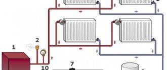
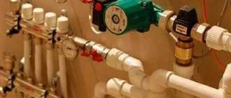
Layout of the heating circulation pump in the system
Three options for calculating thermal power
Difficulties may arise in determining the thermal power index (R), so it is better to focus on generally accepted standards.
Option 1. In European countries it is customary to take into account the following indicators:
- 100 W/sq.m. – for small private houses;
- 70 W/sq.m. – for high-rise buildings;
- 30-50 W/sq.m. – for industrial and well-insulated residential premises.
Option 2. European standards are well suited for regions with mild climates. However, in the northern regions, where there are severe frosts, it is better to focus on the standards of SNiP 2.04.07-86 “Heating networks”, which take into account external temperatures down to -30 degrees Celsius:
- 173-177 W/sq.m. – for small buildings whose number of storeys does not exceed two;
- 97-101 W/sq.m. – for houses of 3-4 floors.
Option 3. Below is a table from which you can independently determine the required thermal power, taking into account the purpose, degree of wear and thermal insulation of the building.
Table: how to determine the required thermal power
Formula and tables for calculating hydraulic resistance
Viscous friction occurs in pipes, shut-off valves and any other components of the heating system, which leads to specific energy losses. This property of systems is called hydraulic resistance. A distinction is made between friction along the length (in pipes) and local hydraulic losses associated with the presence of valves, turns, areas where the diameter of pipes changes, etc. The hydraulic resistance indicator is denoted by the Latin letter “H” and measured in Pa (pascals).
Calculation formula: H=1.3*(R1L1+R2L2+Z1+Z2+….+ZN)/10000
R1, R2 indicate pressure loss (1 – supply, 2 – return) in Pa/m;
L1, L2 – pipeline length (1 – supply, 2 – return) in m;
Z1, Z2, ZN – hydraulic resistance of system components in Pa.
To facilitate calculations of pressure loss (R), you can use a special table that takes into account possible pipe diameters and provides additional information.
Table for determining pressure loss
Averaged data for system elements
The hydraulic resistance of each element of the heating system is given in the technical documentation. Ideally, you should use the specifications specified by the manufacturers. In the absence of product passports, you can rely on approximate data:
- boilers – 1-5 kPa;
- radiators – 0.5 kPa;
- valves – 5-10 kPa;
- mixers – 2-4 kPa;
- heat meters – 15-20 kPa;
- check valves – 5-10 kPa;
- control valves – 10-20 kPa.
Information about the hydraulic resistance of pipes made of various materials can be calculated from the table below.
Pipe pressure loss table
Inclusion in the water supply system
As mentioned above, ready-made pumping stations are more convenient to install and operate than others , the technical characteristics of which are suitable for supplying water to a small house for a family of 2~3 people or a summer house.
Connecting them comes down to a few simple steps:
- Choosing a location.
- Preparing a solid foundation.
- Laying out the necessary pipelines.
- The suction pipe lowered into the well must be equipped with a strainer and a check valve. It should be lowered to a depth no higher than 1 m from the surface of the water.
- Connecting the electrical network and protective grounding.
Attention! All water electric pump units must have protective grounding or grounding, without which their operation is unacceptable. They must be connected to the power electrical panel through an RCD and an overcurrent circuit breaker.
Why do you need a circulation pump?
It is no secret that most consumers of heating services living on the upper floors of high-rise buildings are familiar with the problem of cold radiators. Its cause is the lack of necessary pressure. Because if there is no circulation pump, the coolant moves slowly through the pipeline and, as a result, cools down on the lower floors
That is why it is important to correctly calculate the circulation pump for heating systems
Owners of private households often face a similar situation - in the most remote part of the heating structure, the radiators are much colder than at the starting point. Experts consider the optimal solution in this case to be the installation of a circulation pump, as it looks like in the photo. The fact is that in small houses, heating systems with natural circulation of coolants are quite effective, but even here it would not hurt to think about purchasing a pump, since if you properly configure the operation of this device, heating costs will be reduced.
What is a circulation pump? This is a device consisting of a motor with a rotor immersed in a coolant. The principle of its operation is as follows: by rotating, the rotor forces a liquid heated to a certain temperature to move through the heating system at a given speed, resulting in the creation of the required pressure.
Pumps can operate in different modes. If you set the circulation pump in the heating system to maximum operation, a house that has cooled down in the absence of the owners can be warmed up very quickly. Then consumers, having restored the settings, receive the required amount of heat at minimal cost. Circulating devices come with a “dry” or “wet” rotor. In the first version, it is partially immersed in the liquid, and in the second - completely. They differ from each other in that pumps equipped with a “wet” rotor make less noise during operation.
Video description
Video instructions for calculating pump pressure:
- Excessive number of turns and bends in the trajectory of the water pipeline . The more complex the pipeline geometry, the greater the hydraulic resistance and the greater the internal pressure loss. Therefore, in order for the pump pressure to remain maximum in relation to the original value, the pipe path must be as straight as possible.
- Poor quality sealing . If the initial part of the system, at the point of water intake, is not sufficiently sealed, the pressure characteristics of the equipment will significantly decrease, and the operating noise level will increase.
Important! Excessive water pressure in the water supply occurs when the pump is selected with a certain “reserve” of pressure characteristics. Operating the system in such conditions will lead to constant water hammer, unpleasant noise, and wear of pipes, fittings and devices. Therefore, the pressure force of pumping equipment must be calculated as accurately as possible.
Nominal head
Pressure is the difference between the specific energies of water at the outlet of the unit and at the entrance to it.
The pressure happens:
- Volume;
- Mass;
- Weight.
Before buying a pump, you should ask the seller everything about the warranty
. Weight matters in conditions of a certain and constant gravitational field. It increases as the acceleration due to gravity decreases, and when weightlessness is present, it is equal to infinity. Therefore, the weight pressure, which is actively used today, is inconvenient for the characteristics of pumps for aircraft and space objects.
Full power will be used to start. It is supplied externally as the drive energy of an electric motor or with the flow of water, which is supplied to the jet apparatus under a special pressure.
Types by type of accommodation
According to the method of placement, water supply hydraulic pumps are divided into two classes:
- Surface type . Located away from the water source, they ensure its suction through a pipe lowered into a well or borehole.
- Submersible . They sink completely into the water to a certain depth.
pumping stations are classified into a separate class , which are essentially a compact, self-sufficient water-pressure complex consisting of a surface pump, a membrane accumulator tank, a water pressure switch and a control circuit.
Adjusting circulation pump speeds
Most circulation pump models have a function for adjusting the speed of the device. As a rule, these are three-speed devices that allow you to control the amount of heat that is sent to heat the room. In the event of a sharp cold snap, the operating speed of the device is increased, and when it warms up, it is reduced, despite the fact that the temperature in the rooms remains comfortable for staying in the house.
To change the speed, there is a special lever located on the pump body. Models of circulation devices with an automatic control system for this parameter depending on the temperature outside the building are in great demand.
Calculation example
Basic necessary data for choosing the appropriate surface pump model for water supply at home:
- Maximum fluid flow rate in l/min or m³/h.
- Suction height is the difference between the levels of the pump inlet pipe and the surface of the water in the source.
- Discharge height is the difference in levels between the highest point of the pipeline and the pump outlet pipe.
- The initial pressure for a free-flow well or well is equal to atmospheric pressure.
- Final - the required pressure in the home plumbing system.
- Pressure losses in pipelines depend on the fluid flow and the quality of the surfaces of the internal walls of the pipelines, which create friction for its movement.
The suction height of surface-type hydraulic pumps cannot exceed 10.33 m - the height of the water column creating equal atmospheric pressure.
To simplify calculations , it is rounded to 10 m , and the pressure created is equated to one technical atmosphere, 1 at = 1 kG/cm², or approximately 1 bar ~ 0.98 at.
The discharge height, or pressure, is determined by the technical parameters and power of the unit .
Often the value of pressure is confused with pressure, calling one another. These quantities are equivalent, but not exactly equal to each other. The pressure at the outlet of the pump depends only on its technical characteristics, and the pressure depends on the totality of external conditions : flow rate and liquid consumption, its temperature, altitude above sea level, etc.
When calculating, all system pressure values in pascals, bars, atmospheres and other units lead to equivalent pressure values in meters .
Let's give an example, taking the geodetic level of the pumping station location as zero:
- The fluid flow provided by the hydraulic pump is 40 m³/h. This is quite sufficient consumption for household needs.
- The water level in the well is 4 m below zero.
- The highest point of water rise is 15 m above it.
- The total losses in the inlet and outlet pipelines can be found in the tables for a specific type of pipe, but they are usually calculated based on the fact that for every 10 m of the pipeline 1 m of pressure is lost, therefore we will take them equal to (15 m + 4 m) / 10 = 1 .9 m.
- Let us take the final pressure at the top point to be 1 bar ~ 9.87 m.
The total pressure of the hydraulic pump will be equal to: 4 m + 15 m + 1.9 + 9.87 = 30.77 m.
If the water pumping station is installed not in a caisson located next to the well, but in a house, you should also take into account the pressure loss along the length of the supply pipeline .
For each pump there is an operational characteristic that shows the pressure drop depending on the flow rate and has something like this :
When choosing a specific pump model, you should compare the calculated parameter values with the nameplate values for the selected unit at the required operating point.
The hydraulic power of the pump can be found using the empirical formula: P (W) = 2.725 x Flow (m³/h) x Pressure (m).
For our example we get : 2.725 x 40 x 30.77 = 3.354 kW.
For more information on calculating and selecting a pump for water supply to a country house, watch this video:
Selection of a circulation pump for a heating system criteria
When choosing a circulation pump for the heating system of a private home, they almost always give preference to models with a wet rotor, specially designed for operation in any household lines of varying lengths and supply volumes.
These devices have the following advantages compared to other types:
- low noise level,
- small overall dimensions,
- manual and automatic adjustment of the number of shaft revolutions per minute,
- pressure and volume indicators,
- suitable for all heating systems of individual houses.
Pump selection by number of speeds
To increase operating efficiency and save energy resources, it is better to take models with stepwise (from 2 to 4 speeds) or automatic control of the electric motor speed.
If automation is used to control the frequency, then energy savings compared to standard models reach 50%, which is about 8% of the electricity consumption of the entire house.
Rice. 8 The difference between a fake (right) and an original (left)
What else to pay attention to
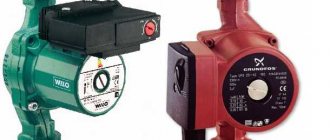
When purchasing popular Grundfos and Wilo models, there is a high probability of counterfeiting, so you should know some of the differences between the originals and their Chinese counterparts. For example, German Wilo can be distinguished from a Chinese counterfeit by the following characteristics:
- The original sample is slightly larger in size and has a serial number stamped on its top cover.
- A raised arrow in the direction of fluid movement in the original was placed on the inlet pipe.
- The de-airing valve on the fake is yellow in brass color (the same color in the Grundfos analogues)
- The Chinese analogue has a bright shiny sticker on the reverse side indicating energy saving classes.
Rice. 9 Criteria for selecting a circulation pump for heating
Once again about the well
A well is undoubtedly the best option for individual water supply at home (read about choosing a source). In one of the articles on the site, I wrote how to make a well yourself (here). Here I will add data on the size of the wells; they are directly related to the calculation of the well pump.
Since a well is drilled with drills whose base is a pipe, it is reasonable to indicate the dimensions of standard wells, as well as the dimensions of pipes, in inches. There are three standard (according to drilling practice) sizes of individual water supply wells:
- Three-inch (75 mm) borehole;
- Four-inch (100 mm) hole;
- The hole is more than 4 inches, usually 110 mm.
- Today, wells up to 150 mm are drilled.
When calculating a well pump, the diameter of the well must be tied to the diameter of the pump, because by definition, the pump must be lowered into the well.
How to choose and buy a circulation pump
Circulation pumps face somewhat specific tasks, different from water pumps, well pumps, drainage pumps, etc. If the latter are designed to move liquid with a specific outlet point, then circulation and recirculation pumps simply “drive” the liquid in a circle.
I would like to approach the selection in a somewhat non-trivial way and offer several options. So to speak, from simple to complex - start with the manufacturers’ recommendations and lastly describe how to calculate a circulation pump for heating using formulas.
Select a circulation pump
This simple way to select a circulation pump for heating was recommended by one of the WILO pump sales managers.
It is assumed that the heat loss of the room per 1 sq. m. will be 100 W. Formula for calculating consumption:
Total heat loss of the house (kW) x 0.044 = circulation pump flow rate (m3/hour)
For example, if the area of a private house is 800 sq. m. the required flow rate will be:
(800 x 100) / 1000 = 80 kW - heat loss at home
80 x 0.044 = 3.52 cubic meters per hour - the required flow rate of the circulation pump at a room temperature of 20 degrees. WITH.
From the WILO range, the TOP-RL 25/7.5, STAR-RS 25/7, STAR-RS 25/8 pumps are suitable for such requirements.
Regarding the pressure. If the system is designed in accordance with modern requirements (plastic pipes, closed heating system) and there are no non-standard solutions, such as high floors or long heating pipelines, then the pressure of the above pumps should be sufficient.
Again, this selection of a circulation pump is approximate, although in most cases it will satisfy the required parameters.
Select a circulation pump using the formulas.
If you want to understand the required parameters and select it using formulas before buying a circulation pump, then the following information will be useful.
determine the required pump pressure
H=(R x L xk) / 100, where
H—required pump head, m
L is the length of the pipeline between the most distant points “there” and “back”. In other words, this is the length of the largest “ring” from the circulation pump in the heating system. (m)
An example of calculating a circulation pump using formulas
There is a three-story house measuring 12m x 15m. Floor height is 3 m. The house is heated by radiators (∆ T=20°C) with thermostatic heads. Let's make the calculation:
required thermal power
N (from pl.) = 0.1 (kW/sq.m.) x 12 (m) x 15 (m) x 3 floors = 54 kW
calculate the flow rate of the circulation pump
Q = (0.86 x 54) / 20 = 2.33 m3/hour
calculate the pump pressure
The manufacturer of plastic pipes, TECE, recommends using pipes with a diameter at which the fluid flow speed will be 0.55-0.75 m/s, the resistivity of the pipe wall will be 100-250 Pa/m. In our case, a pipe with a diameter of 40mm (11/4″) can be used for the heating system. At a flow rate of 2.319 m3/hour, the coolant flow rate will be 0.75 m/s, the resistivity of one meter of pipe wall will be 181 Pa/m (0.02 mWG).
WILO YONOS PICO 25/1-8
GRUNDFOS UPS 25-70
Almost all manufacturers, including such “giants” as WILO and GRUNDFOS, post special programs for selecting a circulation pump on their websites. For the above-mentioned companies these are WILO SELECT and GRUNDFOS WebCam.
The programs are very convenient, they are quite easy to use
Particular attention should be paid to the correct entry of values, which often causes difficulties for untrained users
Buy a circulation pump
When purchasing a circulation pump, special attention should be paid to the selling company. There are currently a lot of counterfeit products on the Ukrainian market.
How can we explain that the retail price of a circulation pump on the market can be 3-4 times less than that of a representative of the manufacturer?
According to analysts, the circulation pump in the household sector is the leader in energy consumption. In recent years, companies have been offering very interesting new products - energy-saving circulation pumps with automatic power control. From the household series, WILO has YONOS PICO, GRUNDFOS has ALFA2. Such pumps consume several orders of magnitude less electricity and significantly save owners’ financial expenses.
Injecting water from depth
How to determine the pump pressure when pumping water from a well, water storage pit or well? The calculation formula takes the following form:
Ntr = Ngeo + Nloss + Nsvob + Source level.
All the terms in it are the same, except for the last one - Source level - which is the difference between the liquid suction point and the pumping device.
Checking the selected electric motor a. Checking the rudder shift duration
For the selected pump, look at the graphs of the dependence of the mechanical and volumetric efficiency on the pressure created by the pump (see Fig. 3).
4.1. We find the moments arising on the electric motor shaft at different steering angles:
,
where: M
α – torque on the electric motor shaft (Nm);
Q
mouth – set pump capacity;
P
α – oil pressure created by the pump (Pa);
P
tr – pressure loss due to oil friction in the pipeline (3.4÷4.0)·105 Pa;
n
n – pump speed (rpm);
η
r – hydraulic efficiency associated with fluid friction in the working cavities of the pump (for rotary pumps ≈ 1);
η
mech - mechanical efficiency, taking into account friction losses (in oil seals, bearings and other rubbing parts of pumps (see graph in Fig. 3).
We enter the calculation data in Table 4.
4.2. We find the rotation speed of the electric motor for the obtained torque values (based on the constructed mechanical characteristics of the selected electric motor - see paragraph 3.6). We enter the calculation data in Table 5.
Table 5
| α° | n, rpm | ηr | Qα, m3/s |
| 5 | |||
| 10 | |||
| 15 | |||
| 20 | |||
| 25 | |||
| 30 | |||
| 35 |
4.3. We find the actual pump performance at the obtained electric motor speeds
,
where: Q
α – actual pump performance (m3/sec);
Q
mouth – installed pump capacity (m3/sec);
n
– actual speed of rotation of the pump rotor (rpm);
n
n – nominal speed of rotation of the pump rotor;
η
v – volumetric efficiency, taking into account the reverse bypass of the pumped liquid (see graph 4.)
We enter the calculation data in table 5. We build a graph Q
α
= f ( α )
– see fig.
4 .
Rice. 4. Graph Q
α
= f ( α )
4.4. We divide the resulting graph into 4 zones and determine the operating time of the electric drive in each of them. We summarize the calculation in Table 6.
Table 6
| Zone | Zone boundary angles α° | Hi (m) | Vi (m3) | Qav.z (m3/sec) | ti (sec) |
| I | |||||
| II | |||||
| III | |||||
| IV |
4.4.1. Find the distance covered by the rolling pins within the zone
,
where: H i
– distance covered by rolling pins within the zone (m);
R o
– distance between the axes of the stock and rolling pins (m).
4.4.2. Finding the volume of oil pumped within the zone
,
where: V i
– volume of pumped oil within the zone (m3);
m
cyl – number of pairs of cylinders;
D
– plunger (rolling pin) diameter, m.
4.4.3. Find the duration of the rudder shift within the zone
,
where: t i
– average duration of rudder shift within the zone (sec);
Q
av
i
– average productivity within the zone (m3/sec) – taken from the graph in clause 4.4. or calculate from table 5).
4.4.4. We determine the operating time of the electric drive when shifting the steering wheel from side to side
t
lane
= t 1 + t 2 + t 3 + t 4 + t o
,
where: t
per – time of shifting the rudder from side to side (sec);
t 1 ÷ t 4
– duration of transfer in each zone (sec);
t o
– time to prepare the system for action (sec).
4.5. We compare t shift with T (time of shifting the rudder from side to side at the request of RRR), sec.
t
lane
≤ T
(30 sec)
Basic installation errors
Let's look at the most common mistakes that many of us make:
- Suction pipe diameter. Quite often, the diameter of the pipeline in practice turns out to be smaller than the diameter of the suction pipe. This design, when connected, increases the resistance on the side of the suction line, thereby reducing the suction depth. In simple terms: a pipeline reduced in diameter is simply not able to pass the size of liquid that the pump easily sucks and pumps.
- Direct connection to a regular hose. Such a system is not particularly critical provided that a low-capacity pump is used. Otherwise, under the influence of the high pressure created by the pump, the hose will shrink, its cross-section will be significantly reduced, and water simply will not be able to pass through it. At best, this will lead to a stop in the water supply, and at worst, to breakdown of the pump without the possibility of its subsequent repair.
- A large number of bends and turns in the pipeline. This installation option does not increase the resistance value and, accordingly, reduces the productivity and pressure of the pump. This is why it is so important to keep the number of bends and turns to a minimum if you want to use the purchased and installed pump at 100%.
- Sealing. It is precisely due to insufficient sealing in the suction section of the pipeline that significant water losses can occur. Poor sealing not only reduces water pressure, but also causes excessive noise during pump operation.
Feeding performance of pumping equipment
This is one of the main factors to consider when choosing a device. Supply – the amount of coolant pumped per unit of time (m3/hour). The higher the flow, the greater the volume of liquid that the pump can pump. This indicator reflects the volume of coolant that transfers heat from the boiler to the radiators. If the supply is low, the radiators will not heat well. If the performance is excessive, home heating costs will increase significantly.
The power of circulation pumping equipment for a heating system can be calculated using the following formula: Qpu=Qn/1.163xDt [m3/h]
In this case, Qpu is the supply of the unit at the design point (measured in m3/hour), Qn is the amount of heat consumed in the area that is heated (kW), Dt is the temperature difference recorded on the forward and return pipelines (for standard systems this is 10- 20°C), 1.163 – indicator of the specific heat capacity of water (if another coolant is used, the formula must be adjusted).
Types of power of the device for the well
When releasing devices, the manufacturer uses the following designations for power types:
- P1 (kW). Input electrical power is that which the electric motor takes from the electrical network.
- P2 (kW). On the shaft of the electric motor - the one that it gives to the shaft. The input electric power of pump P1 is equal to the shaft power of electric motor P2 divided by the efficiency of the electric motor.
- P3 (kW). The input indicator of the hydraulic pump is equal to the value P2 when the coupling that connects the shaft of the device and the shaft of the electric motor does not consume electricity.
- P4 (kW). The useful power of submersible hydraulic pumping equipment is that which comes out during operation in the form of water flow and pressure.
Without relevant experience, it is not recommended to install the pump yourself.
You can calculate the indicator online; there is a special calculator.
How to determine the required pressure of the circulation pump
The head of centrifugal pumps is most often expressed in meters. The pressure value allows you to determine what hydraulic resistance it can overcome. In a closed heating system, the pressure does not depend on its height, but is determined by hydraulic resistance. To determine the required pressure, it is necessary to perform a hydraulic calculation of the system. In private homes, when using standard pipelines, as a rule, a pump that develops a pressure of up to 6 meters is sufficient.
You should not be afraid that the selected pump is capable of developing greater pressure than you need, since the developed pressure is determined by the resistance of the system, and not by the number indicated in the passport. If the maximum pressure of the pump is not enough to pump liquid through the entire system, there will be no circulation of liquid, so you should choose a pump with a headroom reserve
.
Submersible pump power and efficiency
The rated efficiency of a centrifugal pump motor for water supply is the ratio of useful power to that consumed. Designation – η. Distribution formula: η = (P2/P1) * 100. The efficiency of an electric motor will never be higher than one (100%) under any circumstances, since a “perpetual motion machine” does not exist, and any drives have losses.
The power P1 of the electric motor is greater by the amount of mechanical and heat losses Pvmo developing in the electric motor.
Efficiency is the name given to the ratio of hydraulics to power supplied to the shaft of the downhole device, and their difference indicates losses in the unit. Formula: η = (P4/P3) * 100.
The loss of power in a centrifugal pumping device also results from a number of components, namely:
- Hydraulic;
- Mechanical;
- Volume losses Pvs.
Submersible pumps for summer cottages can be purchased at any specialized store.
The total efficiency is the sum of the efficiency of all losses. The efficiency of a device characterizes the degree of design perfection in terms of mechanics and hydraulics.
Tools
0 votes
+
Vote for!
—
Vote against!
When arranging water supply and heating for country houses and dachas, one of the most pressing problems is the selection of a pump. A mistake in choosing a pump is fraught with unpleasant consequences, among which excessive energy consumption is the simplest, and failure of a submersible pump is the most common. The most important characteristics by which any pump must be selected are water flow or pump performance, as well as pump pressure or the height to which the pump can supply water. A pump is not an equipment that can be taken with a reserve - “for growth”. Everything must be adjusted strictly according to needs. Those who were too lazy to make the appropriate calculations and chose the pump “by eye” almost always have problems in the form of failures. In this article we will dwell in detail on how to determine pump pressure and performance and provide all the necessary formulas and tabular data. We will also clarify the subtleties of calculations of circulation pumps and the characteristics of centrifugal pumps.
- How to determine the flow and pressure of a submersible pump
- Calculation of performance/flow rate of a submersible pump
- Calculation of submersible pump pressure
- Calculation of a membrane tank (hydraulic accumulator) for water supply
- How to calculate the pressure of a surface pump
- How to determine the flow and pressure of a circulation pump
- Calculation of circulation pump performance
- Calculation of circulation pump pressure
- How to determine the flow and pressure of a centrifugal pump
How to determine the flow and pressure of a submersible pump
Submersible pumps are usually installed in deep wells and wells, where a self-priming surface pump cannot cope. Such a pump is characterized by the fact that it operates completely immersed in water, and if the water level drops to a critical level, it turns off and will not turn on until the water level rises. Running a submersible pump “dry” without water is fraught with breakdowns, so it is necessary to select a pump with such a performance that it does not exceed the flow rate of the well.
Calculation of performance/flow rate of a submersible pump
It is not for nothing that pump performance is sometimes called flow rate, since calculations of this parameter are directly related to water flow in the water supply system. In order for the pump to be able to meet the water needs of residents, its performance must be equal to or slightly greater than the water flow from simultaneously switched on consumers in the house.
This total consumption can be determined by adding up the expenses of all water consumers in the house. In order not to bother yourself with unnecessary calculations, you can use the table of approximate values of water consumption per second. The table shows all kinds of consumers, such as washbasin, toilet, sink, washing machine and others, as well as the water consumption in l/s through them.
Table 1. Consumption of water consumers.
After summing up the costs of all required consumers, it is necessary to find the estimated flow rate of the system; it will be somewhat less, since the likelihood of using absolutely all plumbing fixtures at the same time is extremely low. You can find out the estimated flow rate from Table 2. Although sometimes, to simplify the calculations, the resulting total flow rate is simply multiplied by a factor of 0.6 - 0.8, assuming that only 60 - 80% of plumbing fixtures will be used at the same time. But this method is not entirely successful. For example, in a large mansion with many plumbing fixtures and water consumers, only 2–3 people can live, and the water consumption will be much less than the total. Therefore, we strongly recommend using the table.
Table 2. Estimated flow rate of the water supply system.
The result obtained will be the actual consumption of the house’s water supply system, which must be covered by the pump’s performance. But since in the pump characteristics the performance is usually calculated not in l/s, but in m3/h, the flow rate we obtained must be multiplied by a factor of 3.6.
Example of calculating the flow rate of a submersible pump:
Let's consider the option of water supply for a country house that has the following plumbing fixtures:
- Shower with mixer – 0.09 l/s;
- Electric water heater – 0.1 l/s;
- Sink in the kitchen – 0.15 l/s;
- Washbasin – 0.09 l/s;
- Toilet - 0.1 l/s.
Let's sum up the consumption of all consumers: 0.09+0.1+0.15+0.09+0.1=0.53 l/s.
Since we have a house with a garden plot and a vegetable garden, it wouldn’t hurt to add a watering tap here, the flow rate of which is 0.3 m/s. Total, 0.53+0.3=0.83 l/s.
We find the value of the calculated flow rate from Table 2: the value of 0.83 l/s corresponds to 0.48 l/s.
And lastly, we convert l/s to m3/h, for this 0.48 * 3.6 = 1.728 m3/h.
Important! Sometimes the pump capacity is indicated in l/h, then the resulting value in l/s must be multiplied by 3600. For example, 0.48*3600=1728 l/h.
Conclusion : the flow rate of the water supply system of our country house is 1.728 m3/h, so the pump capacity should be greater than 1.7 m3/h. For example, the following pumps are suitable: 32 AQUARIUS NVP-0.32-32U (1.8 m3/h), 63 AQUARIUS NVP-0.32-63U (1.8 m3/h), 25 SPRUT 90QJD 109-0.37 (2 m3 /h), 80 AQUATICA 96 (80 m) (2 m3/h), 45 PEDROLLO 4SR 2m/7 (2 m3/h), etc. To more accurately determine the appropriate pump model, it is necessary to calculate the required pressure.
Calculation of submersible pump pressure
The pump pressure or height of water rise is calculated using the formula presented below. It is taken into account that the pump is completely immersed in water, so parameters such as the height difference between the water source and the pump are not taken into account.
Calculation of well pump pressure
Formula for calculating the pressure of a well pump:
Where,
Htr – the value of the required pressure of the well pump;
Hgeo – height difference between the location of the pump and the highest point of the water supply system;
Hloss – the sum of all losses in the pipeline. These losses are associated with friction of water on the pipe material, as well as pressure drop at pipe bends and tees. Determined from the loss table.
Hfree – free pressure on the spout. In order to be able to comfortably use plumbing fixtures, this value must be taken at 15 - 20 m, the minimum acceptable value is 5 m, but then the water will be supplied in a thin trickle.
All parameters are measured in the same units in which pump pressure is measured - in meters.
The pipeline loss calculation can be calculated by examining the table below. Please note that in the loss table, the speed at which water flows through a pipeline of the corresponding diameter is indicated in regular font, and in highlighted font, the pressure loss for every 100 m of a straight horizontal pipeline. At the very bottom of the tables, losses in tees, corner joints, check valves and gate valves are indicated. Naturally, to accurately calculate losses, it is necessary to know the length of all sections of the pipeline, the number of all tees, turns and valves.
Table 3. Pressure loss in a pipeline made of polymer materials.
Table 4. Pressure loss in a pipeline made of steel pipes.
An example of calculating the pressure of a well pump:
Let's consider this option for water supply to a country house:
- Well depth 35 m;
- The static water level in the well is 10 m;
- The dynamic water level in the well is 15 m;
- Well flow – 4 m3/hour;
- The well is located at a distance from the house - 30 m;
- The house is two-story, the bathroom is on the second floor - 5 m high;
First of all, we consider Hgeo = dynamic level + height of the second floor = 15 + 5 = 20 m.
Next we calculate Hloss. Let us assume that our horizontal pipeline is made with a 32 mm polypropylene pipe to the house, and in the house with a 25 mm pipe. There is one corner rotation, 3 check valves, 2 tees and 1 shut-off valve. Let's take the productivity from the previous flow calculation as 1.728 m3/hour. According to the proposed tables, the closest value is 1.8 m3/hour, so let’s round up to this value.
Hloss = 4.6*30/100 + 13*5/100 + 1.2 + 3*5.0 + 2*5.0 + 1.2 = 1.38+0.65+1.2+15+ 10+1.2=29.43 m ≈ 30 m.
Let's take 20 m as free.
In total, the required pump pressure is:
Htr = 20 + 30 + 20 = 70 m.
Conclusion : taking into account all the losses in the pipeline, we need a pump with a pressure of 70 m. Also, from the previous calculation, we determined that its productivity should be higher than 1.728 m3/hour. The following pumps are suitable for us:
- 80 AQUATICA 96 (80 m) 1.1 kW – capacity 2 m3/hour, head 80 m.
- 70 PEDROLLO 4BLOCKm 2/10 – capacity 2 m3/hour, head 70 m.
- 90 PEDROLLO 4BLOCKm 2/13 – capacity 2 m3/hour, head 90 m.
- 90 PEDROLLO 4SR 2m/ 13 – capacity 2 m3/hour, head 88 m.
- 80 SPRUT 90QJD 122-1.1 (80m) – capacity 2 m3/hour, head 80 m.
A more specific choice of pump depends on the financial capabilities of the dacha owner.
Calculation of a membrane tank (hydraulic accumulator) for water supply
The presence of a hydraulic accumulator makes the pump more stable and reliable. In addition, this allows the pump to turn on less often to pump water. And another advantage of the hydraulic accumulator is that it protects the system from hydraulic shocks, which are inevitable if the pump is powerful.
The volume of the membrane tank (hydraulic accumulator) is calculated using the following formula:
Where,
V – tank volume in l.
Q – nominal flow/capacity of the pump (or maximum performance minus 40%).
ΔP is the difference between the pump on and off pressure. The switching pressure is equal to - maximum pressure minus 10%. The shutdown pressure is equal to the minimum pressure plus 10%.
Pon – switching pressure.
nmax – the maximum number of pump starts per hour, usually equal to 100.
k – coefficient equal to 0.9.
To make these calculations, you need to know the pressure in the system - the pump activation pressure. A hydraulic accumulator is an irreplaceable thing, which is why all pumping stations are equipped with it. Standard volumes of storage tanks are 30 l, 50 l, 60 l, 80 l, 100 l, 150 l, 200 l and more.
How to calculate the pressure of a surface pump
Self-priming surface pumps are used to supply water from shallow wells and boreholes, as well as open springs and water storage tanks. They are installed directly in a house or technical room, and a pipe is lowered into a well or other water source, through which water is pumped to the pump. Typically, the suction height of such pumps does not exceed 8 - 9 m, but supply water to a height, i.e. the pressure can be 40 m, 60 m or more. It is also possible to pump water from a depth of 20 - 30 m using an ejector, which is lowered into the water source. But the greater the depth and distance of the water source from the pump, the more the pump’s performance drops.
The performance of a self-priming pump is calculated in exactly the same way as for a submersible pump, so we will not focus on this again and will go straight to the pressure.
Calculation of the pressure of a pump located below the water source. For example, the water supply tank is located in the attic of the house, and the pump is on the ground floor or in the basement.
Where,
Ntr – required pump pressure;
Ngeo – height difference between the pump location and the highest point of the water supply system;
Nloss – losses in the pipeline associated with friction. They are calculated in exactly the same way as for a well pump, but the vertical section from the tank, which is located above the pump, to the pump itself is not taken into account.
Nsvob - free pressure from plumbing fixtures, it is also necessary to take 15 - 20 m.
Tank height – the height between the water storage tank and the pump.
Calculation of the pressure of a pump located above a water source - a well or reservoir, container.
This formula has absolutely the same values as the previous one, only
The height of the source is the difference in height between the water source (well, lake, pit, tank, barrel, trench) and the pump.
An example of calculating the pressure of a self-priming surface pump.
Consider this option for water supply to a country house:
- The well is located at a distance of 20 m;
- Well depth – 10 m;
- Water mirror – 4 m;
- The pump pipe is lowered to a depth of 6 m.
- The house is two-story, the bathroom is on the second floor - 5 m high;
- The pump is installed directly next to the well.
We consider Ngeo - height 5 m (from the pump to the plumbing fixtures on the second floor).
Loss - let’s assume that the outer pipeline is made of a 32 mm pipe, and the inner one is 25 mm. The system has 3 check valves, 3 tees, 2 shut-off valves, 2 pipe turns. The pump capacity we need should be 3 m3/h.
Nloss = 4.8*20/100 + 11*5/100 + 3*5 + 3*5 + 2*1.2 + 2*1.2 = 0.96+0.55+15+15+2, 4+2.4=36.31≈37 m.
Nfree = 20 m.
Source height = 6 m.
Total, Ntr = 5 + 37 + 20 + 6 = 68 m.
Conclusion : a pump with a head of 70 m or more is required. As the selection of a pump with such a water supply has shown, there are practically no models of surface pumps that would meet the requirements. It makes sense to consider installing a submersible pump.
How to determine the flow and pressure of a circulation pump
Circulation pumps are used in home heating systems to ensure forced circulation of coolant in the system. Such a pump is also selected based on the required performance and pump pressure. The graph of pressure versus pump performance is its main characteristic. Since there are one-, two-, three-speed pumps, they have one, two, three characteristics, respectively. If the pump has a smoothly varying rotor speed, then there are many such characteristics.
Calculating a circulation pump is a responsible task; it is better to entrust it to those who will carry out the heating system project, since for calculations it is necessary to know the exact heat loss of the house. The selection of a circulation pump is carried out taking into account the volume of coolant that it will have to pump.
Calculation of circulation pump performance
To calculate the performance of the heating circuit circulation pump, you need to know the following parameters:
- Heated area of the building;
- Power of the heat source (boiler, heat pump, etc.).
If we know both the heated area and the power of the heat source, then we can immediately proceed to calculating the pump performance.
Where,
Qn – pump flow/performance, m3/hour.
Qrequired – thermal power of the heat source.
1,16 – specific heat capacity of water, W*hour/kg*°K.
The specific heat capacity of water is 4.196 kJ/(kg °K). Convert Joules to Watts
1 kW/hour = 865 kcal = 3600 kJ;
1 kcal=4.187 kJ. Total 4.196 kJ = 0.001165 kW = 1.16 W.
tg – coolant temperature at the outlet of the heat source, °C.
tх – temperature of the coolant at the inlet to the heat source (return), °C.
This temperature difference Δt = tg – tx depends on the type of heating system.
Δt= 20 °C – for standard heating systems;
Δt = 10 °C – for low-temperature heating systems;
Δt = 5 – 8 °C – for the “warm floor” system.
An example of calculating the performance of a circulation pump.
Let's consider this option for a house heating system: a house with an area of 200 m2, a two-pipe heating system, made with a 32 mm pipe, length 50 m. The coolant temperature in the circuit has a cycle of 90/70 ° C. The heat loss of the house is 24 kW.
Conclusion: for a heating system with these parameters, a pump with a flow/performance of more than 2.8 m3/hour is required.
Calculation of circulation pump pressure
It is important to know that the pressure of the circulation pump does not depend on the height of the building, as was described in the examples of calculating a submersible and surface pump for water supply, but on the hydraulic resistance in the heating system.
Therefore, before calculating the pump pressure, it is necessary to determine the system resistance.
Where,
Ntr – required pressure of the circulation pump, m.
R – losses in a straight pipeline due to friction, Pa/m.
L – total length of the entire heating system pipeline for the farthest element, m.
ρ is the density of the flowing medium; if it is water, then the density is 1000 kg/m3.
g – gravitational acceleration, 9.8 m/s2.
Z – safety factors for additional pipeline elements:
- Z=1.3 – for fittings and fittings.
- Z=1.7 – for thermostatic valves.
- Z=1.2 – for a mixer or device that prevents circulation.
As it was established through experiments, the resistance in a straight pipeline is approximately equal to R = 100 - 150 Pa/m. This corresponds to a pump pressure of approximately 1 - 1.5 cm per meter.
The pipeline branch is determined - the most unfavorable, between the heat source and the most remote point of the system. It is necessary to add the length, width and height of the branch and multiply by two.
L = 2*(a+b+h)
An example of calculating the pressure of a circulation pump. Let's take the data from the example of calculating productivity.
First of all, we calculate the pipeline branch
L = 2*(50+5) = 110 m.
Ntr = (0.015 * 110 + 20*1.3 + 1.7*20)1000*9.8 = (1.65+26+34)9800=0.063= 6 m.
If there are fewer fittings and other elements, then less pressure will be required. For example, Ntr = (0.015*110+5*1.3+5*1.7)9800=(1.65+6.5+8.5)/9800=0.017=1.7 m.
Conclusion: this heating system requires a circulation pump with a capacity of 2.8 m3/hour and a pressure of 6 m (depending on the number of fittings).
How to determine the flow and pressure of a centrifugal pump
The performance/flow and pressure of a centrifugal pump depend on the number of revolutions of the impeller.
For example, the theoretical head of a centrifugal pump will be equal to the difference in pressure at the inlet to the impeller and at the outlet of it. The liquid entering the impeller of a centrifugal pump moves in a radial direction. This means that the angle between the absolute speed at the wheel entry and the peripheral speed is 90°.
Where,
Нт – theoretical pressure of a centrifugal pump.
u – peripheral speed.
c is the speed of fluid movement.
α – the angle discussed above, the angle between the speed at the entrance to the wheel and the peripheral speed, is equal to 90 °.
Where,
β =180°-α.
those. the pump pressure value is proportional to the square of the number of revolutions in the impeller, because
u=π*D*n.
The actual pressure of a centrifugal pump will be less than the theoretical one, since part of the fluid energy will be spent on overcoming the resistance of the hydraulic system inside the pump.
Therefore, the pump pressure is determined using the following formula:
Where,
ɳg – hydraulic efficiency of the pump (ɳg=0.8-0.95).
ε is a coefficient that takes into account the number of blades in the pump (ε=0.6-0.8).
Calculation of the pressure of a centrifugal pump required to ensure water supply in the house is calculated using the same formulas as given above. For a submersible centrifugal pump, use the formulas for a submersible well pump, and for a surface centrifugal pump, use the formulas for a surface pump.
Determining the required pressure and performance of a pump for a summer house or country house is not difficult if you approach the issue with patience and the right attitude. A properly selected pump will ensure the longevity of the well, stable operation of the water supply system and the absence of water hammer, which is the main problem in choosing a pump “with a large margin by eye.” The result is constant water hammer, deafening noise in pipes and premature wear of fittings. So don’t be lazy, calculate everything in advance.