. INDICATION OF SAFETY PRECAUTIONS…………………………….
Page 2
- Image
- Text
2
CONTENT
1 . SAFETY INSTRUCTIONS
………………………………………………………………………………………………… 3
2. DESCRIPTION AND OPERATION OF THE DEVICE
…………………………………………………………………………………………….. 3
2.1. Purpose of the device
……………………………………………………………………………………………………………….. 3
2.2. Specifications
……………………………………………………………………………………………………. 4
2.3. Contents of delivery
…………………………………………………………………………………………………………………… 5
2.4. Device structure
………………………………………………………………………………………………………………… 5
2.5. Operation of the device “NEVALUX-6011” (“NEVALUX-6014”)
…………………………………………………………… 10
2.6. Operation of the device “NEVALUX-5514”
…………………………………………………………………………………………. 12
3. INSTALLING THE DEVICE
…………………………………………………………………………………………………………….. 14
3.1. Installation location and diagram
……………………………………………………………………………………………………….. 14
3.2. Installation of the device
…………………………………………………………………………………………………………………….. 15
3.3. Connecting the device to the water supply network
……………………………………………………………………… 15
3.4. Connecting the device to the gas network
…………………………………………………………………………………… 16
3.5. Connecting the device to a liquefied gas cylinder
………………………………………………………. 16
3.6. Rules for installing flexible hoses
………………………………………………………………………………………. 16
3.7. Connecting the device to the chimney
…..……………………………………………………………… …….18
3.8. Battery Installation
………………………………………………………………………………………………….. 19
3.9. Checking the device
…………………..……………………………………………………………………………20
3.10. Conversion of the device to a different type and pressure of gas
……..…………………………………………20
4 . USING THE DEVICE
…………………………………………………………………………………………………….. 19
4.1. Turning on the device
………………………………………………………………………………………………………………. 19
4.2. Water temperature regulation
…………………………………………………………………………..21
4.3. Turning off the device
……………………………………………………………………………………………………………. 21
4.4. Replacing the battery
………………………………………………………………………………………………………. 21
4.5. Frost protection
……………………………………………………………………………………………….. 21
4.6. Actions in case of emergency
……………………………………………………..22
5 . MAINTENANCE
………………………………………………………………………………………………. 22
5.1. Inspection
……………………………………………………………………………………………………………………………………. 22
5.2. Care
………………………………………………………………………………………………………………………………………… 22
5.3. Maintenance
……………………………………………………………………………………………………. 22
6. POSSIBLE DEVICE MALFUNCTIONS AND METHODS OF THEIR ELIMINATION
……………………………. 24
7. TRANSPORTATION AND STORAGE RULES
………………………………………………………………………. 27
8 . WARRANTY
…………………………………………………………………………………………….. 28
9 . CERTIFICATE OF ACCEPTANCE
…………………………………………………………………………………………………… 29
10.
NOTE ABOUT INSTALLING THE DEVICE AND CONDUCTING MAINTENANCE
….. 29
11.
CATALOG OF DEVICE COMPONENTS
……………………………………………………………………………..30
12. SERVICE CENTERS FOR MAINTENANCE OF NEVALUX WATER HEATERS
……………………36
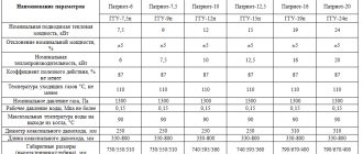
Parameter table
Neva geysers are available in 12 models. They have different characteristics, which are discussed in detail in the comparative table.
Models differ in design, number of possible connections, power, heating volume per 1 minute. Capable of operating at low water supply pressure. Equipped with a multi-level security system and made of high-quality materials. The manufacturer provides a long warranty on the equipment. Instructions for each speaker are included in the package.
We recommend an article on the topic! Technical characteristics of geysers Vaillant.
gas outlet pipe...
Page 6
- Image
- Text
6
B)
1
– pipe of the gas exhaust device; 2 – facing; 3 – viewing window;
4
– mounting holes; 5 – cold water supply fitting, G 1/2 thread;
6
– gas supply fitting, thread G 1/2; 7 – hot water outlet fitting, G 1/2 thread;
8
– water temperature display; 9 – button to decrease the set temperature;
10
– button to increase the set temperature; 11 – battery discharge indicator.
Figure 1. Appearance, overall and connecting dimensions of the device:
A) – “NEVALUX-6011”; B) – “NEVALUX-6014”
1
– pipe of the gas exhaust device; 2 – facing; 3 – viewing window; 4 – gas flow valve handle;
5
– cold water supply fitting, G 1/2 thread; 6 – gas supply fitting, thread G 1/2; 7 – hot outlet fitting
water, thread G 1/2; 8 – mounting holes.
Figure 2. Appearance, overall and connecting dimensions of the device
«
NEVALUX-5514
»
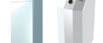
General description of the model range
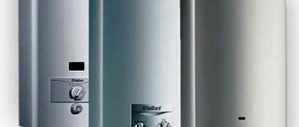
Neva water heaters operate from natural and liquefied gas. The body of gas models is made of copper. The burner is ignited by automatic ignition, which is powered by AA batteries.
Neva models are equipped with safety sensors, which makes using the device safe and convenient. Thanks to these small devices, the gas supply is regulated, which makes the dispenser economical in fuel consumption.
Depending on the power, Neva water heaters are capable of heating from 6 to 14 liters of cold liquid in a minute to a temperature of at least 25 degrees. Many gas models are equipped with a temperature support system. Some Neva speakers have the ability to connect 2 taps at once, so hot water is used in 2 places (for example, kitchen, bathroom) at the same time. The display on the body shows the selected heating temperature.
Thanks to high-quality cladding materials, you cannot get burned on the column. Some gas equipment has a color design, there is a pattern on the heater body.
To choose a water heater, it is important to consider:
- the required volume of heating water, the power of the apparatus;
- water heating speed;
- number of water intake points;
- column mount;
- sizes, design.
gas exhaust device...
Page 7
- Image
- Text
7
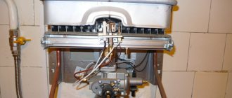
1
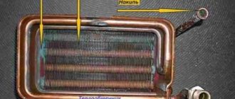
– gas exhaust device; 2 – heat exchanger; 3 – pilot burner; 4 – water temperature sensor;
5
– cold water supply fitting; 6 – gas supply fitting; 7 – hot water outlet fitting;
8
– flame presence sensor; 9 – candle; 10 – main burner; 11 – electronic control unit; 12 – water-gas unit;
13
– battery compartment; 14 – plug for draining water; 15 – water flow tap (located under the lining);
16
– thermal relay (traction sensor); 17 – fitting for measuring inlet gas pressure; 18 – plate; 19 – frame;
20
– screws for fastening the cladding.
Figure 3. View of the device “NEVALUX-6011” without cladding
Principle of operation
In atmospheric water heaters, you first need to light the pilot light directed towards the burner. Then the hot water tap opens, which increases the pressure inside the system. The design of the water unit of the gas column (or “frog”) is such that the flow passing through it affects the internal membrane, which moves the rod directly connected to the gas valve. The valve moves back, thus opening the supply of gas-air mixture to the burner. When interacting with the pilot flame, the mixture ignites and the water begins to warm up inside the coil.
The water warms up all the time the liquid supply tap to the point of consumption is open. The flame strength is adjusted manually. After closing the mixer, the pressure inside the system drops, the membrane returns to its previous position and the fuel supply valve closes.
This is how the operating principle of the old gas water heating system looks like. Newer models, unlike the old gas model, are ignited by an electric spark produced by batteries, a hydrogenerator, and the electrical network. The required temperature (and therefore the flame strength) is set on the display of the control unit and the water heater automatically maintains it.
Let us briefly look at the design features of water heaters from the most common manufacturers.
gas exhaust device...
Page 8
- Image
- Text
8
1
– gas exhaust device; 2 – heat exchanger; 3 – pilot burner; 4 – water temperature sensor;
5
– cold water supply fitting; 6 – gas supply fitting; 7 – hot water outlet fitting;
8
– flame presence sensor; 9 – candle; 10 – main burner; 11 – electronic control unit; 12 – water-gas unit;
13
– battery compartment; 14 – plug for draining water; 15 – water flow tap (located under the lining);
16
– thermal relay (traction sensor); 17 – fitting for measuring inlet gas pressure; 18 – plate; 19 – frame;
20
– screws for fastening the cladding.
Figure 4. View of the device “NEVALUX-6014” without cladding
gas exhaust device...
Page 9
- Image
- Text
9
1
– gas exhaust device; 2 – heat exchanger; 3 – pilot burner; 4 – gas flow valve; 5 – supply fitting
cold water; 6 – gas supply fitting; 7 – hot water outlet fitting; 8 – flame presence sensor; 9 – candle; 10 -
main burner; 11 – electronic control unit; 12 – water-gas unit; 13 – battery compartment;
14
– water drain plug with valve; 15 – water flow tap (located under the lining); 16 – thermal relay (sensor
traction); 17 – frame; 18 – screws for fastening the cladding; 19 – plate; 20 – thermal relay (water overheating sensor); 21 –
microswitch (water flow sensor); 22 – fitting for measuring inlet gas pressure.
Figure 5. View of the device “NEVALUX-5514”
without cladding
Geyser Neva Lux 5514
_______________________________________________________________________________
Installation of a gas water heater Neva 5514
The Neva Lux-5514 household flow-through geyser is designed for heating water used for household purposes in apartments and individual residential buildings. The wall-mounted device (Fig. 1) has a rectangular shape formed by a removable lining 2. On the front side of the lining there are: handle 4 for controlling the gas flow valve, viewing window 3 for observing the flame of the ignition and main burners. All main elements of the apparatus are mounted on the rear wall 17 (see Fig. 2).
Fig.1. Dimensions of the apparatus 1 – gas outlet pipe; 2 – facing; 3 – viewing window; 4 – gas flow tap handle; 5 – cold water supply fitting, G 1/2 thread; 6 – gas supply fitting, thread G 1/2; 7 – hot water outlet fitting, G 1/2 thread; 8 – mounting holes. Fig.2. Type of device without housing 1 – gas exhaust device; 2 – heat exchanger; 3 – pilot burner; 4 – gas flow valve; 5 – cold water supply fitting; 6 – gas supply fitting; 7 – hot water outlet fitting; 8 – flame presence sensor; 9 – candle; 10 – main burner; 11 – electronic control unit; 12 – water-gas unit; 13 – battery compartment; 14 – water drain plug with valve; 15 – water flow tap (located under the lining); 16 – thermal relay (traction sensor); 17 – posterior wall; 18 – screws for fastening the cladding; 19 – plate; 20 – thermal relay (water overheating sensor); 21 – microswitch (water flow sensor); 22 – fitting for measuring inlet gas pressure. Elements and components of the Neva Lux-5514 geyser - gas exhaust device 1 (see Fig. 2) is designed to discharge combustion products into the chimney; — heat exchanger 2 ensures the transfer of heat obtained from gas combustion to water flowing through its pipes; — pilot burner 3 is designed to ignite the main burner of the water heater; — flame presence sensor 8 provides control of the operation of the pilot and main burners; — spark plug 9 is designed to create a spark discharge to ignite the pilot burner; — main burner 10 is designed to create and burn an air-gas mixture; — electronic control unit 11 provides control of ignition and gas supply to the ignition and main burners; — water-gas unit 12 is designed to control the gas supply to the pilot and main burners and consists of water and gas units and a valve block (the design of the unit ensures gas supply to the pilot and main burners only in the presence of water flow); — plug 14 serves to drain water from the water circuit of the VPG-24 water heater to prevent it from freezing; the safety valve built into the plug is designed to protect the water circuit of the water heater from increased water pressure; — thermal relay 16 is designed to turn off the device if there is no draft in the chimney; — thermal relay 20 is designed to turn off the device when the water in the heat exchanger is heated to more than 90 C. Operation of the gas water heater Neva Lux-5514 When water begins to flow through the water unit 17 (see Fig. 3) with a flow rate of at least 2.5...3 l/min the membrane rod 18 of the water unit opens the gas valve 24, and the contacts of the microswitch 21 are closed. Then the valve 28 opens the gas supply from the membrane cavity of the valve block 26 to the ignition burner 3 and from the control unit 11 high voltage current pulses are supplied to the spark plug 9.
Spark discharges between the tip of the spark plug and the pilot burner nozzle ignite the pilot burner. After the pilot burner ignites, which is determined by the presence of flame sensor 8, valve 27 closes the gas supply to the membrane cavity of the valve block, gas from the membrane cavity exits through the pilot burner and membrane 29 of the valve block, due to the pressure difference, gas supply valve 30 to the main burner opens 10. The main burner ignites and the pilot burner goes out. The operation of the main burner of the water heater is controlled by the presence of flame sensor 8. Tap 4 regulates the flow of gas supplied to the main burner to obtain the required water temperature at its set flow rate: turning the tap counterclockwise increases the gas flow and water temperature; turning the tap clockwise reduces gas flow and water temperature. The tap 15 changes the water flow within insignificant limits and at the same time affects the displacement of the membrane 18 and, accordingly, the opening value of the valve 24. Turning the tap clockwise reduces the water flow and increases the displacement of the membrane and gas flow, which leads to an increase in the water temperature. Turning the tap counterclockwise increases water flow and reduces membrane displacement and gas flow, which leads to a decrease in water temperature. Accordingly, tap 15 also influences the value of water flow at which the device is turned on (ignition of the pilot and then the main burner) and turned off (turning off the main burner). When the tap is turned clockwise all the way, the water heater turns on at a flow rate of 2.5 l/min, and turns off at a flow rate of 2 l/min. When the tap is turned counterclockwise all the way, the water heater turns on at a flow rate of 3 l/min, and turns off at a flow rate of 2.5 l/min. When the flow of water stops or when its flow rate decreases to less than 2...2.5 l/min, the contacts of the microswitch 21 open, valves 24 and 30 close and the main burner goes out. The Neva 5514 geyser is equipped with safety devices that ensure: - gas access to the burners only if there is a water flow; — gas access to the main burner during ignition only if there is a flame on the ignition burner; — stopping the gas supply to the main burner when it goes out; — turning off the main burner in the absence of draft in the chimney; — turning off the main burner when the water flow stops; — turning off the main burner when water is heated to more than 90° C; — shutdown of the main burner when the power supply is interrupted.
Rice. 3. Working diagram of the gas water heater Neva Lux-5514 1 – gas exhaust device; 2 – heat exchanger; 3 – pilot burner; 4 – gas flow valve; 5 – cold water supply; 6 – gas supply; 7 – hot water drain; 8 – flame presence sensor; 9 – candle; 10 – main burner; 11 – electronic control unit; 12 – water-gas unit; 13 – battery compartment; 14 – plug for draining water with valve; 15 – water flow tap; 16 – thermal relay (traction sensor); 17 – water unit; 18 – membrane of the water unit; 19 – Venturi fitting; 20 – thermal relay (water overheating sensor); 21 – microswitch (water flow sensor); 22 – fitting for measuring inlet gas pressure; 23 – gas unit; 24 – two-stage valve; 25 – gas outlet to the main burner; 26 – valve block; 27 – electromagnetic servo valve (normally open); 28 – pilot burner electromagnetic valve (normally closed); 29 – valve block membrane; 30 – main burner gas valve; 31 – gas outlet to the ignition burner; 32 – cold water outlet to the heat exchanger; 33 – water filter; 34 – gas filter.
Installation and assembly of the geyser Neva Lux-5514
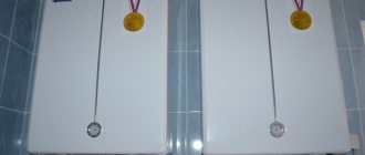
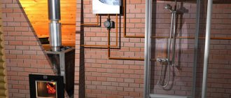
Location and installation diagram The Neva 5514 geyser must be installed in kitchens or other non-residential heated premises in accordance with the gasification project. The volume of the room where the water heater is installed must be at least 8 m3. The room where the water heater is installed must have good ventilation and a constant flow of fresh air (a window or an opening transom), since oxygen is burned when the device operates. The bars or gap at the bottom of the door or wall should not be completely closed. The device must be connected to a chimney with good draft (vacuum 1.96...29.4 Pa) and must be installed as close to the chimney as possible. One of the available methods for checking the draft in a chimney is shown in Figure 4. Installation must be carried out on fireproof walls - brick, concrete (with or without ceramic tile lining). It is allowed to install the device on fire-resistant walls, provided that the wall is insulated with a galvanized sheet 0.8...1 mm thick over a sheet of basalt thermal insulating cardboard BTK 3...5 mm thick. The wall insulation must protrude beyond the dimensions of the apparatus body by at least 100 mm on each side (see Fig. 5). The distance from the side surfaces of the unit to fire-resistant walls without the use of insulation must be at least 250 mm. When the specified distance is reduced to 150 mm, it is necessary to install thermal insulation (covering the walls with a galvanized sheet over a sheet of heat-insulating material). When installing the water heater on fireproof walls, insulation is not required. It is prohibited to install the device on wooden walls; plastered walls with a wooden base; on walls covered with flammable materials. Do not install the device above a source of heat or open flame. The installation location and height of the device must ensure that all requirements are met. It is recommended to install it at such a height that the viewing window is at eye level of the consumer or as close as possible to this level. Fig.5. Installation of the device on fire-resistant walls Also, to carry out service maintenance when installing the unit, it is necessary to maintain the following gaps: - the distance from the side surface of the device to the side wall is at least 150 mm; — the free space in front of the front surface must be at least 600 mm. The installation diagram is shown in Figure 6. It is recommended to first connect the device to the water supply network, fill the water system and then connect it to the gas network.
Figure 6. Installation diagram Connection to the water supply network To increase the service life of the Neva Lux-5514 geyser and improve its performance characteristics, it is recommended to install a water purification filter in front of the device (see Fig. 6). To facilitate subsequent maintenance, a shut-off valve must be installed in front of the unit on the cold water supply line. The shut-off valve must be easily accessible. The device must be connected to the water supply network using metal pipes or flexible hoses with an internal diameter of at least 13 mm. The length of the flexible hose for supplying and discharging water should be no more than 2.5 m. Connect cold water to the cold water supply fitting 5, and hot water to the hot water drain fitting 7 (see Fig. 1), having previously removed it from the fittings protective plugs. Connecting cold and hot water pipelines should not be accompanied by mutual tension of pipes and parts of the device in order to avoid displacement or breakage and violation of the tightness of the water system. Before connecting to the water supply network, it is necessary to open the cold water supply for a while to clean the water supply pipe and prevent unwanted dirt and deposits from entering when first turned on. After connecting the pipelines to the device, it is necessary to check the tightness of the connections. Checking the tightness is carried out in the following order: - open the hot water tap; — open the cold water shut-off valve in front of the device; — after filling the apparatus tract with water, close the hot water tap and inspect the connections. Leakage at the joints is not allowed. It is also recommended to inspect the connections of the water path of the device, since their tightness may be compromised if the conditions of transportation and storage are violated. If necessary, tighten the connections. Connecting the Neva 5514 geyser to the gas network To increase the service life of the device and improve its performance characteristics, it is recommended to install a gas filter in front of it (see Fig. 6). To ensure stable operation of the device, it is necessary to connect the gas line with metal pipes or a flexible hose with an internal diameter of at least 14 mm. The flexible gas supply hose, in accordance with the requirements, must be resistant to the supplied gas at a given pressure and temperature.
The length of the flexible hose should be no more than 2.5 m. Connect the pipes or flexible hose to fitting 6 (see Fig. 2), having first removed the protective plug from it. When installing gas pipelines, the number of dismountable connections must be kept to a minimum. When installing a gas line, a shut-off valve must be installed at the entrance to the device. The shut-off valve must be easily accessible. Connecting a gas pipe should not be accompanied by mutual tension between pipes and parts of the unit in order to avoid displacement or breakage of its individual parts and assemblies and violation of the tightness of the gas line. After connecting the unit to the gas line, its connections to the communications must be checked for leaks.
Checking the tightness at the gas supply connections is carried out with the device not working and the shut-off valve in the open position. Gas leakage is not allowed. Checking the tightness of gas connections is carried out by washing the joints (or other safe methods without using open flame sources). The appearance of bubbles means a gas leak.
Operation of the gas water heater Neva Lux-5514
Switching on and starting To start a gas water heater, in general, you need to: - install the battery in the battery compartment; — open the cold water shut-off valve in front of the device; — open the shut-off valve on the gas pipeline in front of the device; - open the hot water tap, and spark discharges should begin between the spark plug and the pilot burner (if the flow rate of water passing through the device is at least 2.5 l/min), the spark discharges should ignite the pilot burner, and, from the pilot burner , the main burner should light up. After the main burner is ignited, the pilot burner should go out. The water flow required for ignition is adjusted using tap handle 15 (Fig. 2). The water heater is switched on in the extreme left position of the handle (minimum water flow) at a water flow rate of 2.5 l/min, and switched off at 2 l/min. This position of the handle is recommended at reduced inlet water pressure (at low water flow rates provided by the water supply network). Switching on in the extreme right position of the handle (maximum water flow) occurs at a water flow of 3 l/min, switching off – at 2.5 l/min. This position of the handle is recommended to obtain a large flow rate of warm water at the outlet of the device at normal inlet water pressure (at a water flow rate of 6 l/min or more provided by the water supply network). When first put into operation after its installation or after a long break in operation, the ignition of the pilot burner will occur only after air has been removed from the gas communications. Since spark discharges last no more than 60 seconds after turning on the water, to continue ignition it is necessary to close the hot water tap and then open it again.
This procedure must be repeated several times until the air is completely released from the communications and the pilot burner is ignited. Adjusting the water temperature
Fig. 10. Positions of the handle of the gas flow tap Adjusting the water temperature at the outlet of the Neva Lux-5514 geyser is done in one of the following ways: - by rotating the handle 4 of the gas flow tap (Fig. 10): turning the handle clockwise to the “Minimum flow” position reduces the gas flow and water temperature, turning the knob counterclockwise to the “Maximum flow” position increases gas flow and water temperature; - changing the flow of water passing through the apparatus with a hot water tap: an increase in water flow (at flow rates of more than 4...6 l/min) leads to a decrease in its temperature, a decrease in water flow leads to an increase in its temperature. Overheating of water in the heat exchanger leads to noise during operation of the water heater and causes the rapid formation of scale in the heat exchanger pipes and a narrowing of their flow area, which over time will lead to a decrease in operating efficiency and a weakening of the hot water jet. Therefore, to reduce the temperature of the water leaving the device, it is not recommended to use a mixer by adding cold water, but rather use the methods described above. The water heating temperature is limited by the heating capacity of the device: with high water flow, especially in winter, the water leaving it may have an insufficient temperature even at maximum gas flow. In this case, to increase the water temperature, it is necessary to reduce the flow of water passing through the water heater. When the water flow rate decreases to 2...2.5 l/min or less, the device automatically turns off. Turning off the geyser Neva Lux-5514 To turn off the device, just stop the flow of water through it by closing the hot water tap.
After closing the tap, make sure that the main burner has completely gone out. If, after closing all the hot water taps, the main burner continues to operate, you must immediately shut off the gas supply to the appliance using the gas shut-off valve installed in front of the appliance and call a specialized service organization for repairs. At the end of using the heater (at night, for a long time away from home, etc.), it must be turned off, observing the following sequence: - close the hot water taps; — close the gas shut-off valve at the entrance to the apparatus; — close the cold water shut-off valve at the entrance to the device. If the water is hard, before turning it off, it is recommended to reduce the water temperature at the outlet of the device as much as possible to reduce the formation of scale. Replacing the battery When the battery is discharged, a sign of which is the absence or significant weakening of spark discharges between the spark plug and the pilot burner after water begins to flow through the device (with a flow rate of more than 2.5 l/min), it is necessary to install a new element in battery compartment 13 (Fig. .2). When installing the battery, you must observe the polarity in accordance with the picture on the inside of the compartment cover. It is recommended to install a battery type LR20 (alkaline), which has a larger capacity and ensures longer operation of the unit. Installing low-quality batteries or low-energy batteries will lead to their rapid discharge and loss of performance. The battery must be replaced when the device is not working.
_______________________________________________________________________________
_______________________________________________________________________________
_______________________________________________________________________________
- Gas boilers
- Electric boilers
- Gas water heaters
- Malfunctions and repairs of geysers
- Water heaters
- Boiler error codes
- Troubleshooting boilers
- Troubleshooting water heaters
- Repair of indirect heating boilers
- Troubleshooting electric convectors
_______________________________________________________________________________
_______________________________________________________________________________
- BOSCH TERM 4000
Models WR-13, WR-13. Specifications. Installation. Maintenance and adjustments.
- NEVA 4510
Design and main components. Installation and connections.
- NEVA 4511
Purpose of main components and elements. Maintenance and replacement of parts.
- NEVA 4513
Adjustments and settings. Service maintenance.
- NEVA
Design features. Malfunctions and maintenance.
- NEVA LUX 5514
Elements and components. Installation and assembly. Operation and adjustments.
_______________________________________________________________________________
_______________________________________________________________________________
- NEVA REPAIR
In operation, the Neva VPG-12E gas water heater, after turning on the hot water tap, the water heater lights up, but the temperature does not rise above 20 degrees. The water pressure is normal, it does not respond to the regulator for increasing the flame, as it was 18-20 degrees, it remains so. What could be the problem?
- ARISTON
I connected the Ariston Marco Polo Gi7s speaker. Everything is working. But the device turns on the second time. That is, you turn on the water, the column starts up, clicks and goes into error E1. Then he closed the tap, opened it and it started. Powered by a cylinder. Is this possible because after it works I turn off the gas?
- ELECTROLUX
There is a malfunction of the Electrolux 275 geyser, when you turn on the hot water, everything lights up and works for 5-7 minutes, after which there is a click in it and it goes out along with the igniter. Tell me what is the problem?
_____________________________________________________________
- OASIS
Malfunction of the Oasis TUR 20 geyser. In the “Summer” mode, the gas and water regulator is at maximum. It goes out on its own, sometimes after 5 minutes, sometimes after 30. In the “Winter” mode, with any combination of controls, it goes out after 30-40 seconds. What can be wrong? Water supply via flexible hoses. Could they be the cause? If yes, what should I replace it with?
- VECTOR
Tell me, I have this problem: when the water is turned off, the column lights up on its own, the temperature rises and does not turn off (I had to take out the batteries), I put the batteries back in (I don’t turn on the water), it lights up, what should I do?
- ASTER
Help me find the reason, geyser Astra 8910-02, when hot water is turned on it goes out from time to time, I cleaned the thermocouple until it shines, the membrane is in good condition, but just in case I replaced it with a new one, the water pressure is less than that of cold water, what else note?
- BOSCH
I installed and put into operation a Bosch WR 13 gas water heater. I switched the nozzles to liquefied gas, removed the jumper from j6, that is, switched it to liquefied gas mode, but the water heater does not work, who knows anything about this? When turned on, the green button lights up for a couple of seconds, and then the red button starts blinking and only the fan turns on.
- JUNKERS
The Junkers gas water heater began to malfunction. It works for 15-20 minutes and goes out. You turn the water off and on, the igniter lights up, and after a few seconds it goes out, and you can do this no matter how many times, it doesn’t light up. A little time passes - it works, and everything repeats again. The water pressure is good, as is the gas pressure. What could be the reason?