A real Russian stove or its possible modifications have not lost their relevance even in the modern world. If we do not consider cases when brick structures are installed in a house that is not constrained by its dimensions for a design solution, while the heating task is entrusted to more promising systems, brick stoves are still often found as the main source of heat. With the current pace of advancement of civilization in the Russian hinterlands, we can say with confidence that we will meet again for a very long time.
Warmth in the house is not the only task facing brick devices. The ability to cook food on a stove is realized by a heating and cooking brick oven. It differs somewhat from the classic stove in the way it is arranged in the area where the stove is installed. The remaining fundamental units have not undergone any significant changes.
Selecting a furnace model
If there is a sufficient amount of theoretical and practical material on a narrow topic in the field of construction, few will miss the opportunity to save a certain amount of money and do the work themselves, because building a brick stove with your own hands eliminates the need to pay for the work of a master.
Construction of a furnace is a lengthy and energy-intensive process. Everything is complicated by the preparatory stage, at which you will have to make calculations of the main parameters, decide on the choice of the furnace model, and get acquainted with the design of this model.
Undoubtedly, advanced experience from professional craftsmen greatly simplifies the tasks of independent construction. All parameters, drawings, diagrams of various models are collected into a single document called a project. A novice master can only choose the most suitable projects for his tasks and use ready-made standard calculations. But even the choice of a finished model should be made on the basis of certain criteria, and not spontaneously, as many people think who have never encountered such an issue as heating stoves.
Despite the fact that technical calculations largely relate to the firebox and chimney, it is necessary to evaluate the dimensions of the stove itself and the size of the room in which it is planned to be installed. Bulky brick ovens for a home with a hob in a small room will look ridiculous. And this will not make the heating process more efficient, because in order to heat a large structure, it will have to be heated longer. The size ratio can be found in RuNet along with the project.
The location of the furnace will influence the choice of model. Ovens with a stove should be oriented so that the units used for cooking face the kitchen, and the back and side walls heat adjacent rooms. But this is just practical advice and the owner has the right to choose where to put the stove.
The sequential masonry scheme presented in the project will allow the construction of one of three stove options: T-shaped, square or rectangular. The T-shaped device is installed in the center of the room, partially zoning it. It effectively heats several rooms at once. This principle was implemented in peasant huts. First, the stove for the house was built, and then the log house itself was erected.
The remaining two types can serve as island or wall models.
The compact stove does not take up much space, while being an effective source of heat. This model is designed specifically for cottages and small country houses. It allows you to warm up the room, adapting it for long-term living in winter.
Video description
We suggest watching the following video, which will help you understand in detail the procedure for forming a hatch leading to the basement of a private house:
When cutting reinforcing elements with a grinder, you should act with extreme caution. The geometric parameters and characteristics of the tool used can cause the grinder to become jammed between the protruding parts of the reinforcement. This phenomenon may cause injury to the installer. In the absence of an autogen, a small cut is made on the sledgehammer, and then the cut site is hit with a sledgehammer.
Choosing an installation location
This issue should be considered separately, because when solving it, it is necessary not only to take into account the recommendations, but also to follow some rules. The classic option would be an island arrangement of the stove, and in the place where the walls dividing the room into rooms intersect.
Controls facing the kitchen will eliminate unnecessary waste in the house, which often occurs when delivering firewood, kindling or cleaning the ash pit. The walls of the stove partially serve as the walls of the room, so they should not be blocked or curtained. These are not only fire safety requirements, but also the need for daily inspection of the condition of the masonry.
All brick heating and cooking stoves are equipped with a chimney. The pipe should not rest against the floor beam. It must be possible to isolate it from flammable ceiling materials.
The nuances of finishing the stove
The walls of the stove, made of good brick, and even decorated on the outside, do not need to be finished: whitewashed and plastered. If there are no chips or cracks on the masonry elements, and the verticals and horizontals were observed during construction, the heating structure will still look great.
On stove masonry made of high-quality brick, it is enough to grout and carefully unstitch the seams. Without unnecessary finishing, the heating and cooking structure looks better.
If there are still complaints about the stove walls, there are defects on them, and the masonry is not ideal, then finishing is very necessary. Before finishing work, the outer surface is thoroughly mopped, rubbed with a piece of brick to improve adhesion, and then wait for it to dry.
The dried unit can be plastered using the clay-sand mortar used in the masonry. To increase strength, it is possible to add 1% asbestos chips to the composition. Heating options for stoves are lined with tiles - this is the most reliable and gas-tight, but also the most labor-intensive type of finishing.
Design features and operating principle
A stove that provides cooking is somewhat different from one that provides only heat to the home. In the summer, the stove and stove will have to be heated, but all the heat released should go to heating the stove and be immediately removed. This is achieved by installing a special damper that redirects heated air through channels inside the housing.
The fundamental structure of all wood-burning stoves is the same. It is possible to identify common elements that perform specific functions.
- The ash pan serves as a container for collecting ash. It is located at the bottom of the oven and is a chamber with a door for removing ash. But this door is also a blower. Through it, air enters the firebox. The position of the door determines the intensity of fuel combustion.
- Fuel combustion occurs in the firebox. In different furnace models, designers have tried in various ways to increase the proportion of energy converted into useful energy. Therefore, fireboxes are equipped with various screens that focus radiation. The efficiency of the furnace depends on the size of the firebox, so when building it yourself there should be no amateur activity. You must adhere to strictly established sizes.
- The chimney ensures the removal of combustion products from the room. But before the smoke enters the chimney, it passes through a labyrinth of channels inside the stove, giving off its heat to the masonry. When the stove is switched to summer mode, the smoke from the firebox immediately enters the chimney.
- The damper closes the chimney, increasing or decreasing draft. But its main purpose is to prevent heat loss into the atmosphere. After the stove has completely burned out, the damper is completely closed.
- The hob, usually made of cast iron, is heated directly by the flame. But contact with open fire is harmful to any material, including dishes, so a barrier is built in the firebox that cuts off the flame, and after this barrier a hob is installed.
- Other elements, determined by the technical features of a particular model, can be represented by cleaning doors, additional channels, parts for arranging an oven and oven.
Briefly about the main thing
Laying slabs may be required during the construction of buildings for various purposes. When performing work, the characteristics and type of mounted elements are taken into account. They can be monolithic, ribbed or hollow. The choice depends on the purpose of the structure being built, the characteristics of the foundation and a number of other factors.
Before installation work begins, a set of preparatory measures is carried out, including leveling the foundation and forming access roads for lifting equipment.
Then the installation itself is carried out, with the position of the plates adjusted and fixed relative to each other and to the base. With large opening widths, the space is filled in various ways, the choice of which depends on the characteristics of the structure being built.
Order example
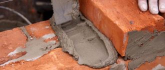
The current furnace laying diagram contains drawings so that the user can imagine what he is trying to build, as well as an order that clearly shows the location of each brick. These project instructions must be followed to the utmost precision. Even a small discrepancy can lead to mismatch of components or incorrect operation of the device as a whole. The ordering allows you to calculate the required amount of material for construction. As in other stove business, the laying of a stove with a hob is done using clay mortar, since cement mortar can collapse at high temperatures.
The most popular model has become the Swedish stove, or, as it is popularly called, “Shvedka”. It is quite small, but at the same time it effectively uses energy, turning it into useful heat. The furnace firebox uses pyrolysis technology, so such models are quite economical, because with the same fuel consumption, the Shvedka reaches 85% efficiency.
The presented procedure is comprehensive for laying out a functional stove yourself, even without some experience in this matter. In the first and second steps, the base is formed. It is laid on a specially prepared foundation. Moreover, it is important to remember that the home structure and the stove are two separate buildings and their foundations must be separate. Next, the formation of the ash pit, firebox and oven begins. The ash pan in the 5th row is covered with a grate and gives way to the main firebox.
The oven is heated not by a flame, but by warm air, but this temperature is enough to cook some dishes in it. The oven body is made of metal and inserted into the formed niche. In the central part between the firebox and the oven, you can see the barrier mentioned above. In the 10th row this barrier ends, allowing the entire stove to be heated. But from the diagram it is clear that one part of the stove is heated by flame, and the other by hot air. This fact is taken into account when cooking when you need to quickly lower the temperature. The pan is simply moved along the stove to the opposite edge.
In further rows, all attention is focused on the formation of channels. The beginning of the diagram shows the movement of warm air in winter and summer. You can notice that heat is released in vertical channels arranged along almost the entire height of the furnace. This is one of the features of the Swede. In order to overlap in the 17th row, a sheet of slate is laid. In row 30, a damper is installed, and the chimney turns into a regular pipe.
The procedure for covering large openings
If the opening is wide enough, floor slabs can only be laid on the foundation using additional elements. In order not to destroy the entire product, two methods are used. In the first case:
- determine the amount of free space that should be filled during installation, divide it by two;
- install the first slab, prudently departing from the edge a distance numerically equal to the obtained value;
- install all slabs in accordance with the requirements of the regulations;
- measure the remaining space, which should be numerically equal to the distance left earlier when installing the first slab;
- fill the gap on both sides of the structure, laying cinder blocks with their ends facing the main surface;
- control the position of the block holes, which should be directed to the side.
Blocks will help block free space Source stroyimdom.com
In terms of labor intensity, the second method is significantly superior to the first. In this case, having previously determined the amount of free space, distribute it evenly between the laid slabs. After installation is completed, the resulting gaps are sealed as follows:
- a board is attached from below between the slabs, which can act as formwork;
- reinforcement is placed in the space;
- concrete solution is prepared;
- the free space is filled with concrete mortar.
Preparation of the solution
To prepare the solution yourself, you need to get medium-fat clay. Exceeding this indicator in any direction will lead to destruction of the masonry.
It is not recommended to mix clay with sand right away, as coarse-grained elements will appear in the solution. First, the clay is soaked and crushed using a mesh. Then a solution of a certain consistency is prepared. In order to check the amount of water in the solution, you need to roll up a rope and roll it into a ring. If no breaks are found at the bend, then the fat content of the clay and the amount of water are normal.
From the description, it seems that preparing the solution is quite simple, but you need to have certain skills. Even experienced craftsmen often make mistakes and redo the batch. To avoid these mistakes, which can cost a lot on your wallet, it is better to purchase a ready-made semi-finished product at a hardware store.
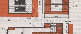
A kitchen stove without an oven has a plan size of 510 * 890 mm, height with an average joint thickness of 5 mm - 770 mm. Heat transfer with two fireboxes per day is 700 kcal/hour. The plate is placed under a cast iron plate measuring 710*410 mm. It can be connected to the heating panel or chimney both from the side opposite the firebox and from any side. The hole for connection to the chimney or heating panel is made on the third row of masonry and has a cross-section of 130*130 mm.
Combustion chamber width 260 mm, height 350 mm. Flue gases wash the cast iron floor slab, go down through a vertical channel with a cross-section of 130*260 mm (1/2 * 1 brick) and go into the connecting channel. A readout door is installed opposite the connecting channel.
Materials required for laying a kitchen stove
Appearance, overall dimensions and row laying of the kitchen stove.
A small brick stove-stove with an oven (oven) is an ideal option for a summer residence. Such a summer kitchen can be installed both inside the house and even outside, in the fresh air.
We offer instructions for laying a mini-stove with a height of 770 mm, a length of 1020 mm and a width of 640 mm. To work you will need a brick, clay mortar, doors for the firebox and ash pan, a grate, five cast iron stoves with burners (t-530x180 mm), a smoke damper, steel tape, strapping, construction felt, oven, roofing steel.
The operating principle of the furnace that we propose to make:
- Gases come from the fuel compartment under the cast iron flooring;
- Then the smoke penetrates the vertical channel and falls under the oven;
- They then rise again, heating the back of the oven;
- After this, warm gases are directed through a special hole into the chimney, heating the heating shield along the way.
A large selection of ready-made factory models for a summer kitchen at reasonable prices may persuade you to decide to buy a finished product, rather than rack your brains over where to buy high-quality building materials, how to install all the elements, etc. But you must admit: having built the stove with your own hands, you, as the owner, can be truly proud of yourself, and the finished structure will become a real “highlight” of your home or garden plot.
Types by method of support
The slab used for interfloor separation is a reinforced reinforced concrete structure with voids. The holes in the slabs come in various shapes and sizes to lighten the weight of the structural element.
The choice of interfloor slab and the depth of its support depends on the design features of the building. The following parameters are taken into account:
- purpose of the building (residential, industrial, public);
- the material from which the structure is constructed;
- wall thickness;
- types of loads acting on both the slabs and the building;
- seismic characteristics of the development area.
Based on the type of support, interfloor slabs are divided into three categories. Their selection is carried out at the project planning stage, taking into account calculations of the loads acting on the load-bearing elements of the building.
On both sides
The support for such slabs is two opposite load-bearing walls. They are laid on capital elements, with narrow (transverse) sides. Most often, for this type, interfloor slabs with round voids are used, marked PK, 1PK, 2PK. They can withstand loads of up to 800 kg/m².
On three sides
They have reinforced end reinforcement and are laid on three load-bearing walls. They are mounted in the corners of the building, which have a U-shaped structure of load-bearing walls. They are marked PKT and can withstand loads of up to 1600 kg/m².
On four sides
Such slabs are reinforced with reinforcement at all ends, they are more rigid and have increased load-bearing capacity. They are used only in complex structures where maximum distribution of high loads is required, or in cases where the construction of additional superstructures is planned. They are marked PKK, indicating increased strength. They are practically not used in low-rise construction.
Order: 12 rows and the stove-stove is ready!
Before starting to lay the stove and stove, lay two layers of felt or asbestos, cover them with roofing steel and nail them down.
IMPORTANT! The asbestos and felt must first be soaked in a clay solution.
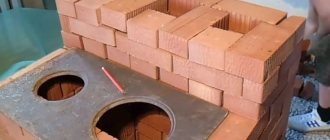
1st row. Lay out the row along the drawn rectangle, checking the order. It is recommended to use a whole brick, but it is acceptable for the middle to be filled with halves.
2nd. It is laid out exclusively from solid brick. An important point: observance of bandaging of seams between rows is a prerequisite for high-quality masonry. How to put it is indicated in the order in the figure.
3rd. At this stage, a place is left where ash and soot will accumulate. The cleaning door is also installed here.
4th. At the back of the row, a space or a special hole is left for later connection of the chimney. After this, the brick is placed on its edge so that something like a partition is obtained. Note! Between the brick standing on the edge and the masonry inside the stove, a distance of 130 mm is left for the channel through which hot gases will flow from under the oven. Here comes the laying of such an important element as the blower.
Types of used anchor products
Depending on the type of buildings, load-bearing elements, installation location and purpose, the following types of anchor products differ:
- Wedge type, consisting of bolts with spacer-type bushings and cone-shaped caps. Installation is carried out in materials with a dense structure (solid brick, concrete or natural stone, reinforced concrete). Fixation occurs as a result of the bushing jamming in the load-bearing walls and friction against the walls of the hole. The frequency of use is due to the ease and speed of installation. The main disadvantage is only one-time use.
- Bushing, the principle of operation is similar to wedge ones. The main disadvantage is the need to drill large holes to connect the structures.
- Driven, in which the bushings are notched at one end. When the element is struck, a wedge-shaped expansion of the bushing occurs. The strength of the connection is ensured by friction against the hole and the internal stop. The advantage lies in the ease of installation and resistance to mechanical influences. High precision clearances are required for a reliable connection.
- Chemical action. Bonding of structures is carried out by pumping adhesive compositions into the fastening channels. The plus is ease of installation, and the minus is high cost.
- A separate type is a special-purpose anchor. The following subspecies are distinguished:
- ceiling - suspension of various designs
- foundation, for fixing foundation elements;
- Moli anchors - used inside hollow structures or weak-bearing structures (hollow brick, plasterboard, chipboard).
Review of more complex stoves with oven and stove
The oven described above is mainly suitable for cooking. The functionality of a small barbecue stove, which is usually installed outdoors, has approximately the same functionality. But there are also more complex designs that successfully perform not only “culinary” but also heating functions. For example, it could be...
- Oven with water box. Its heat output is about 600 kcal/h when heated twice a day.
- Swedish oven. The main advantages of this option are compactness combined with high efficiency.
- Double-bell oven. Effectively heats a room up to 45 sq. m., but at the same time is very compact. The dimensions of the base are 5x4 bricks or 5x3.5 bricks.
Repairing stoves with an oven and stove has its own specifics, like any other stove design for a bathhouse or home. However, this topic deserves separate and detailed consideration.
Anchoring reinforcement
Anchoring in reinforcement frames is carried out to allow the rods to absorb the forces acting on them by installing anchors of various designs at their ends or by inserting the reinforcement beyond the design sections to a length that ensures the inclusion of the rods in joint work. In the fixation zones, the reliability of fastening stretched reinforcing bars in concrete or the transfer of forces from elements working in compression to the concrete is ensured. The necessary calculations are carried out at the stage of design development of structures.
Anchoring of reinforcement in concrete is carried out using the following main methods or a combination of them:
- using straight ends of rods (not acceptable for smooth reinforcing steel);
- the device of bends in the form of hooks or loops at the end of the rods, as well as bends (the legs are bent only when using a periodic profile). This method is not recommended in compressed areas. The minimum diameters of bends or bends must ensure the impossibility of splitting or destruction of concrete at the bends and within them. The radius of the arc must be ≥ 10 times the diameter of the rods, with clamps attached to the bent sections to protect the elements from unbending;
- welding of transverse shorts;
- fastening various anchor devices (set heads, plates, nuts, washers, angles and other elements) to the ends of the rods.
The anchorage length of the reinforcement is ≥ 15 rod diameters and at least 20 cm, with a sufficient thickness of the protective concrete layer to protect them from corrosion.
Joining of non-prestressing reinforcement ≤ 36 mm in tensile zones is allowed by overlapping by knitting or welding of rods. The joints should be spaced apart in places where minimum torque and bending moments are applied. The length of the overlap, mainly performed by rods A-III, depends on their diameters. The building codes contain special tables, so for 10 mm rods the overlap should be 30 cm, and for 25 – 76 cm.
Calculation of the required anchorage length should take into account:
- method of execution;
- profile, diameter and class of reinforcement;
- presence of transverse elements;
- arrangement of rods in cross section;
- stress state of concrete in the anchorage zone and its strength characteristics.
When welding anchors, the method and conditions of welding work and the weldability characteristics of reinforcing steel must be taken into account.
Prestressed reinforcement with a periodic profile and steel ropes, when tension is applied to the stops and the concrete has sufficient strength characteristics, can be placed in the structure without the use of anchors, and bundles of smooth high-strength wire are necessarily secured in the concrete with special anchoring.
When tensioning concrete, it is important to ensure good transfer of stresses from the reinforcement to it. Steel plates are installed under the anchor devices to ensure that the concrete absorbs forces from the reinforcement equally
The ends of the structures are strengthened by installing additional welded mesh, clamps and spirals.
Reinforcing bundles are stretched to specified stresses by placing jacks at the ends of the elements, after which the wire bundles are wedged with conical tubes in steel blocks using a special piston pulled out from the jacks.
More powerful reinforcement beams are secured with glass-type anchors. Grabbing the body of the anchor, the jack pulls it away, focusing on the concrete and creating a gap from the end of the structure, into which washers with longitudinal slots are installed. In this way, the reinforcement beams are fixed in a state of a given voltage.
What to do if you can’t evenly lay out the panels
Considering the significant mass of the panels and increased overall dimensions, it is difficult to ensure stability of the gaps between the plates and their uniform laying on the supporting surface. In addition, often the dimensions of the room do not correspond to the dimensions of the slabs, and, as a result, an open area is formed. In this situation, the free space should be concreted.
Procedure:
- Fasten the formwork panels to the bottom plane of the slabs.
- Lay the reinforcing mesh.
- Pour the concrete solution.
- Seal small gaps with cement mixture.
What are the main types of reinforced concrete slabs?
| Purpose | Peculiarities | Appearance |
| PB, 3.1PB and 1.6PB | Lightweight slabs 1.6PB and 3.1PB. They have a thickness of 160 mm and are used only in the construction of low-rise buildings. PBs have the usual height for floor slabs of 220 mm. Development is carried out on special machines where formwork is not used. After hardening, the workpiece is cut into slabs of equal size. | |
| PNO and PC | PNOs are lightweight, their thickness is 160 mm, and PCs have a standard height of 220 mm. They are produced using older technology using formwork; reinforcing mesh and special void-forming structures are installed in the mold and concrete is poured. Smoothing is carried out on special vibrating machines. |
Factories also produce special slabs that are used for construction in seismically active areas. Such slabs are called ribbed due to the presence of additional stiffeners on both sides.
How to divide monolithic reinforced concrete panels into parts
When performing installation activities, it becomes necessary to reduce the length of the standard panel. To complete the task, you can use a regular grinder with a diamond wheel designed for cutting concrete. You will also need a disc for cutting steel reinforcement, a sledgehammer and a crowbar.
Carry out work on cutting slabs according to the following algorithm:
- Mark the required panel size with chalk.
- Place a backing along the markings to protect the concrete from chipping.
- Cut the reinforced concrete slab along the chalk line.
- Apply blows with a sledgehammer to the top plane and end surfaces.
After the unnecessary piece of slab settles under its own weight, perform the following operations:
- Use a crowbar to break through the bottom of the concrete panel.
- Use a grinder to cut the reinforcement using a metal disc.
First, a cut is made with a grinder on the upper surface of the slab along the marked line
Following the given sequence of operations, it is easy to cut the panel along the longitudinal axis. In this case, using a grinder with a metal circle, you will have to cut the metal mesh used to strengthen the slabs.
Useful tips
You cannot install slabs with broken hinges.
The installation of slabs is constantly monitored. The quality of covering products, certificates and passports for them are checked. The correctness of storage and transportation is taken into account. During the work, compliance with the project, the quality of sealing joints and welding of embedded parts are examined. If the joints are filled with concrete in winter, the area is heated until the mixture completely hardens.
On large-scale construction, joints are checked after reaching the design strength, and the installation is checked using levels and laser levels. If there were changes to the project, detailed drawings are made, welding logs are kept, connections are sealed, and hidden work reports are drawn up.
You cannot install slabs that have broken hinges or are not cleaned of dirt or adhering layers. During the break, the raised structures are not left hanging, but are laid down after welding is completed. You cannot level the panels with a crowbar after removing the slings, nor can you move them through the air in winds exceeding 15 m/s or in fog.
Calculation and layout drawings are carried out before the construction of foundations in order to accurately determine the position of walls and columns in space and ensure the correct support depth.
HOME
Currently, in our country, the most popular are three methods of constructing floors in a house.
This is the installation of floor slabs, the installation of a monolithic reinforced concrete floor and the installation of floors using wooden (less often metal) beams. We will definitely talk about all these methods and more. And the first technology we will consider is the installation of ready-made floor slabs. First, a little about the floor slabs themselves. Depending on their shape, all slabs can be divided into flat and ribbed. Flat ones, in turn, are divided into solid and hollow. We are now interested in empty ones, because... It is this type of slab that is used mainly in low-rise construction.
Hollow core slabs, in turn, are also classified according to various parameters, such as the shape and size of the voids, the thickness of the slabs, the manufacturing technology of the slabs, and the method of reinforcement.
I will not delve into the topic of classification. It is better to look for this information on the websites of manufacturers of reinforced concrete products (reinforced concrete products). We'd better talk directly about installation.
The very first point that you need to pay attention to even at the stage of designing your future home is the opportunity to purchase in your area exactly the slabs of the sizes that are included in the project. Each manufacturer has its own specific range of products and it is always limited. This is really important and I am surprised that very often developers forget about this recommendation and then they have to either cut one or several slabs or make a monolithic section on the floor. We'll talk more about this below.
Storing floor slabs at a construction site.
Of course, it’s great if you have the opportunity to lay floor slabs immediately when they are delivered directly from the car that brought them. But most often this does not happen. Or the driver insists that you unload the slabs as quickly as possible, because... he is in a hurry for the next order, or the slabs are not laid on the machine in the order you need, or you simply bought them in advance and are not going to lay them yet. In all these cases, the slabs will need to be stored on your site.
Try to choose a flat surface for this. Never place slabs directly on the ground. Be sure to put something under the edges of the slab, for example, scraps of wooden beams. There should be only two pads, at a distance of approximately 25-40 cm from the edges. Pads cannot be placed under the middle of the slab.
The slabs can be stored in stacks up to 2.5 meters high. Make the shims for the first slab higher, so that if they are possibly pressed into the ground when laying subsequent slabs, the first slab should never touch the ground, otherwise it could easily break. It is enough to make all subsequent linings even from an inch (2.5 cm). They must be stacked strictly one above the other.
Preparation for installation of floor slabs.
Preparation begins at the moment when the masons cast out the last rows of masonry. The slabs will lie flat and without differences if the upper rows of load-bearing walls are level and in the same horizontal plane.
To achieve this, there must be horizontal level marks in all corners of the room being covered. They are placed during the construction of walls using a level, or a laser level, or a hydraulic level. And when the last row of masonry is done, the distance from the marks to the top of the walls is controlled with a tape measure. It should be the same in all corners. From my experience I can tell you for sure that some masons neglect this, especially when they do backfill masonry at the same time as the face masonry, which is done “under the rod”.
The top row of brickwork of load-bearing walls must be bonded. That is, if you look from the inside of the covered room, then on the load-bearing walls (on which the floor slabs rest) in the very top row of the masonry, only the pokes should be visible.
If the slabs are placed on a load-bearing partition 1.5 bricks thick (that is, the slabs rest on it on both sides), then the top row of such a partition is laid out in one of two ways:
Before laying floor slabs on walls made of various blocks (foam concrete, gas silicate, slag, etc.), it is necessary to make a reinforced concrete belt (usually about 15-20 cm thick). Such a belt is made either by pouring concrete into the formwork, or using special U-shaped blocks along the entire perimeter of the house box, i.e. not only on load-bearing walls, but also on non-load-bearing ones.
When installing hollow core slabs, the holes in them must be sealed. It is much more convenient to do this in advance, while the slabs are still on the ground. In general, SNiP prescribes that voids must be sealed on the side of the slab that rests on the outer wall (to reduce the likelihood of freezing of the slab), and on the side that rests on the internal partition, only starting from the third floor from the top of the house and below (to increase strength). That is, if, for example, the house has a basement floor, a floor between the 1st and 2nd floors, and an attic floor above the 2nd floor, then it is mandatory to fill the voids on the side of the load-bearing partitions only in the basement floor.
I will say that we always seal holes when laying slabs. Moreover, recently, more and more often, round-hollow slabs come from factories with the holes already sealed. It's comfortable. If the holes are not sealed, we insert a one-and-a-half brick (you can even use half) into them and fill the remaining cracks with mortar.
Also, before installing the slabs, it is necessary to prepare the site for the crane in advance. It’s good if in the place where the crane will stand the soil is, as they say, compacted. It's worse when the soil is bulky. If you have a basement, you should not place the faucet too close to the house, in order to avoid what is shown in the figure below:
In such cases, it is better to order a truck crane with a longer boom. Also, sometimes in the place where the crane will stand, you first have to put several road slabs (usually used ones are found somewhere). Often this has to be done in the fall in rainy and slushy weather, when the area is so “broken” that the crane simply gets stuck on it.
Laying floor slabs.
Three people are enough to install floor slabs. One hooks the slabs, two lay them down. If you want, you can do it together, although not always. It happens that when covering, for example, the second floor, the installers and the crane operator do not see each other. Then, at the top, in addition to the 2 people directly laying the slab, there must be another person who will give commands to the crane operator.
Laying begins from the wall on a layer of mortar no more than 2 cm. The mortar should be thick enough so that the slab does not squeeze it completely out of the seam. After the crane operator places the slab on the walls, he first leaves the slings taut. At the same time, using a crowbar, if necessary, it is not difficult to move the slab a little. If the upper surfaces of the load-bearing walls were made smooth, then the slabs will lie evenly, without differences, as they say, “from the first approach.”
Regarding the amount of support of the slabs on the walls, I will give an extract from the document “Manual for the design of residential buildings. Vol. 3 (to SNiP 2.08.01-85) 6. COLORS:
Paragraph 6.16.:
The depth of support of prefabricated slabs on walls, depending on the nature of their support, is recommended to be no less than, mm: when supported along the contour, as well as two long and one short sides - 40; when supported on two sides and the span of slabs is 4.2 m or less, as well as on two short and one long sides - 50; when supported on two sides and the span of the slabs is more than 4.2 m - 70.
When assigning the depth of support for floor slabs, you should also take into account the requirements of SNiP 2.03.01-84 for anchoring reinforcement on supports.
In our practice, we try to make the support no less than 12 cm, fortunately now it is possible to purchase exactly the slabs that are needed. The step of their lengths is 10 cm.
I often hear debates about whether it is possible to support hollow-core floor slabs on three sides (two short and one long) and how far the long side of the slab can be placed on the wall. From what is written above, it follows that it is possible to support the slabs this way. But it is not so. If you read the specified SNiP, it says that slabs that rest on three sides have a different reinforcement pattern than those that rest on only two sides.
The vast majority of hollow core slabs that are currently produced by concrete factories are designed specifically to be supported on two short sides, so it is not recommended to place them on the wall with their long side. Under a certain load, this can lead to cracking of the slab. The reinforcement scheme and, therefore, the possibility of supporting the slab on a third side must be clarified with the manufacturer.
Another mistake associated with improper loading of the slab is covering two spans at once (see figure below):
Under certain unfavorable conditions, the slab may crack, and the location of the crack is completely unpredictable. If you still use such a scheme, use a grinder to make a cut (to the depth of the disk) on the upper surface of the slab strictly above the middle partition. Thus, if something happens, the crack will pass precisely along this cut, which, in principle, is no longer scary.
Of course, it’s good if we manage to cover ourselves exclusively with whole slabs. But circumstances are different and yet sometimes some slab (or even more than one) has to be cut lengthwise or crosswise. To do this you will need a grinder with a diamond disc for concrete, a sledgehammer, a crowbar and not the weakest guy at a construction site.
To make work easier, it is better to place the slab on a lining. Moreover, this lining is placed exactly under the cut line. At a certain moment, the slab will simply break along this line from its own weight.
First of all, we make a cut on the upper surface of the slab with a grinder along the cut line. Then, striking with a sledgehammer from above, we cut a strip along the top of the slab. It is quite easy to penetrate concrete in void areas. Next, we use a crowbar to break through the lower part of the slab (also through the voids). When cutting a slab lengthwise (we always cut along the hole in the slab), it breaks quite quickly. When chopping across, if the slab does not break after breaking the lower part with a crowbar, a sledgehammer is used to strike the vertical partitions of the slab from the side until the victory is achieved.
During the cutting process, we cut the reinforcement that comes across. You can use a grinder, but it’s safer to use welding or a gas cutter, especially when the reinforcement in the slab is pre-stressed. The grinder disc can bite. To prevent this from happening, do not cut the reinforcement completely, leave a couple of millimeters and then tear it apart with a blow from the same sledgehammer.
Several times in our practice we had the opportunity to cut slabs lengthwise. But we have never used, so to speak, “stumps” less than 60 cm wide (less than 3 holes remain), and I do not advise you to. In general, when deciding to cut a slab, you take full responsibility for the possible consequences, because not a single manufacturer will officially tell you that cutting a slab is possible.
Let's now see what can be done if you still don't have enough slabs to completely cover the room:
Method 1 - place the first or last (maybe both) slabs without bringing the long side to the wall. We fill the remaining gap with bricks or blocks, hanging them no more than half from the wall (see figure):
Method 2 - we make the so-called “monolithic section”. Plywood formwork is placed underneath the slabs, a reinforcement frame is made (see figure below) and the area between the slabs is filled with concrete.
Anchoring of floor slabs.
After all the slabs are laid, they are anchored. In general, if the construction of a house is carried out according to a project, then it must contain an anchoring scheme. When there is no project, we usually use the circuit shown in the figure:
The anchor is made by bending the end into a loop, which clings to the mounting loop of the slab. Before welding the anchors to each other and to the mounting loops, they must be tensioned as much as possible.
After anchoring, we immediately seal all mounting eyes in the slabs and rustications (seams between the slabs) with mortar. Try not to delay this so that construction debris does not get into the rustics, and water does not pour into the eyelets during rain and snow. If you suspect that water has gotten into the slabs (for example, you bought slabs with voids already filled, and rainwater could have gotten in even while being stored at the factory), it is better to let it out. To do this, after installation, simply drill one small hole in the slabs from below with a hammer drill, into the voids where the mounting lugs are located.
It is especially dangerous to find water in voids in winter, when the house is not yet heated (or not completed at all) and the slabs freeze below zero. Water saturates the bottom layer of concrete, and with repeated freezing-thawing cycles, the slab simply begins to collapse.
Another way to secure the slabs is to construct a so-called concrete ring anchor. This is a kind of the same monolithic reinforced belt, only it is not made under the slabs, but in the same plane with them, also around the entire perimeter of the house. More often this method is used on houses made of aerated concrete, foam concrete and other blocks.
Let me make a reservation right away that we have never used it because it is much more labor intensive. I think that a ring anchor is justified in more earthquake-prone regions than our Nizhny Novgorod region.
At the end of the article, I suggest watching a short video that talks about choosing floor slabs:
SEE OTHER ARTICLES ON THIS TOPIC:
- Hip roof design with rafters supported on floor beams.
- Building a house with your own hands. Ways to save.
- How to protect an unfinished house in winter?
The best way to express gratitude to the author is to share the link to the article with your friends!
| Parasites live inside everyone! Doctor's advice - take 120 ml of boiling water and... Read more |
Look, this way you can “slow down” your electric meter by 2 times! ...Completely LEGAL! You need to take the one closest to the meter... Read more