One of the best ways to ensure a comfortable temperature in a house or apartment is to install a heated floor system. This system itself consists of many elements, each of which is integral and important. But a special place among them is occupied by the distribution comb, also known as the underfloor heating manifold. Without it, the system cannot function normally and provide its owners with high-quality and comfortable heating of residential premises. Let's look at what a comb for a heated floor is, how it is designed and by what principles it works.
Comb for heated floors
Features of the operation of water heated floors
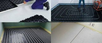
Water heated floors are used as the main or additional source of heat in private homes. The idea of this system is based on laying thermal circuits and pipelines with coolant circulating through them in the screed. The liquid is heated in a boiler and then distributed through floor loops in different rooms. The main feature of the operation of such a system is the need to maintain a low, uniform temperature across a large number of consumers. The coolant comes from the boiler heated to 60 - 70 degrees, such heat from the floors will be uncomfortable for residents. To reduce the temperature, a mixing unit is included in the system or RTL valves (reverse flow regulator) are installed.
The second feature of heated floors is associated with the uneven distribution of coolant throughout the system. The rooms have different areas, which means the contours will be of different lengths. Redistribution occurs at the collector.
Briefly about the main thing
The equipment of the collector block must meet the requirements for the functionality of the system. The collector device ensures uniform heating of the heating elements and a constant temperature in the room. Made from the following materials: polypropylene, brass and steel.
The manifold consists of a system to which threaded elements, fittings or control valves are connected. The collector is installed in a special cabinet or brackets are used.
Along with it, a mixing unit is used.
The durability of combs directly depends on the material and workmanship. You can purchase a ready-made distribution block or assemble it yourself from individual elements.
| Additionally The exhibition of houses “Low-Rise Country” expresses sincere gratitude to the specialists for their assistance in creating the material. – supplier of water supply and heat supply systems for any facilities, from the world's leading brands. The company also develops and installs automated metering systems for energy consumption. If you need more detailed advice, you can use the following contacts: |
What does the collector group consist of?
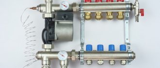
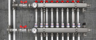
The collector has the form of a metal or plastic tube in which the coolant is collected and redistributed along the circuits. The collector group usually consists of two combs: supply and return, a pumping and mixing unit and additional equipment.
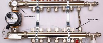
On the left is a pumping and mixing unit with a thermal head, on the right is a manifold comb with rotameters and a drain valve.
Collecting combs
The main differences between the supply and return combs are only in the shut-off valves. The heated coolant from the boiler comes to the supply, then the liquid is redistributed between the heating devices. The substance (water, ethylene glycol or propylene glycol) passes through the circuit, gives off heat and returns to the return comb, from where it goes back to the boiler.
Read more about choosing a coolant for a heating system in a separate article.
How it works?
The collector combs have a larger diameter compared to the pipes, because of this the coolant in the distribution block slows down its movement. Distribution occurs through pipes with a smaller flow. One comb can have up to 14 pipes, depending on the number of heating devices. Typically, the supply is equipped with adjusting devices to change the flow of underfloor heating circuits. More coolant will flow into a pipe with a higher throughput, and accordingly the heating devices will heat up more.
Shut-off valve options
To regulate the amount of coolant on the collector, ball valves, valves, flow meters (rotameters), thermostatic push-action valves or servos are used.
- Ball valves are shut-off valves with two positions: (open and closed), allowing you to stop the movement of the coolant through a separate pipe of the comb. Ball valves do not allow you to regulate the flow, so it makes sense to use them in heated floors, where the loops are approximately equal in length. They are also placed in front of collectors.
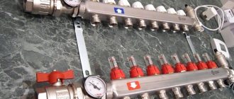
An example of a manifold with ball valves.
- The valves allow for stepwise changes in the flow diameter and require manual control of the system.
There are flow meters on the top of the supply comb, and thermostatic valves on the bottom of the return.
- Flow meter (rotameter) is a device that measures fluid flow per unit of time. It is a transparent flask with a stem inside; the mechanism of operation of the valves is similar to a regular valve.
The coolant flows along a shorter line with less hydraulic resistance - the flow meter on such loops narrows the passage, and on longer ones it widens it, due to this the floor in different rooms heats up equally.
- Thermostatic pressure valves are installed on the return comb of the underfloor heating manifold. They can close or open depending on the return temperature. The TSG valve is equipped with a Eurocone, which allows you to measure the temperature of the liquid in the pipe.
- Thermoelectric servo drive is a thermostatic head that can remotely control the operation of the comb valves. Servo drives are divided into normally closed and normally open. In the first case, in the normal position the valve is closed and opens when voltage is applied. The servo drive is connected to a thermostat, which is located in the room and responds to changes in air temperature.
The thermoelectric servo drive should not be confused with RTL valves. The first reacts to changes in room temperature, the second is adjusted to the temperature of the coolant.
Thermoelectric head with servo drive.
Why do you need a distribution comb?
main pipe distribution collector system
What will change after installing the distribution comb:
- The pressure in the pipes will be equalized throughout the room.
- The problem of sudden cooling of water in the bathroom when you turn on the tap in another place will disappear
- The house will be heated evenly
This is only part of all the advantages of manifold pipe routing after installing the comb. To minimize uneven water supply, the comb should be installed for both cold and hot water. Special taps are installed on it; they allow you to shut off the flow of water in a separate unit; this is convenient in the event of a leak in the toilet or a broken tap in the bathroom.
Should I assemble a collector or buy a ready-made one?
Collectors can be prefabricated, ready-welded or homemade. Let's consider their advantages and disadvantages.
Ready welded
They are usually produced in the form of supply and return combs welded together with a specified number of pipes.
Advantages
- Fast installation - no need to assemble fasteners.
- Minimum qualification requirements for an installer
Flaws
- Difficult to configure for a specific system.
- The number of pipes may not meet the needs, in which case they will have to be blocked off with plugs and not used.
- The collector can be equipped with elements that are unnecessary for a particular heating system. For example, it may have a hydraulic distributor (hydraulic arrow), which is only useful in networks with a large number of pumps.
- The return and feed combs may be welded together, making it difficult to attach separate loops to them. The pipes on factory mixers are usually located at the same distance from each other, but this is not always convenient.
Homemade
You can make a collector with your own hands from available materials: steel pipes with a round or square cross-section. To do this, holes are cut in them and pipes are welded. Couplings are made from round sections of smaller diameter.
Advantages
- Making a collector with your own hands is profitable from a financial point of view.
- You can make a drawing and manufacture an individual manifold for a specific system.
Flaws
- To perform this job, you will need skills in working with a welding machine.
- It will take more time.
- The non-separable design makes it difficult to repair and replace individual elements.
Prefabricated
Such distribution units are assembled from factory parts, which are purchased separately or as a kit. They will be discussed further.
Advantages
- There is variability when designing a collector unit for a specific heating system.
- Does not require special skills or equipment for installation.
- Possibility of separate dismantling of feed and return combs.
- High installation speed.
Flaws
- Components from different manufacturers may not fit together.
- This option usually costs more.
Manufacturing companies
Different countries and companies are producing such devices. The highest quality devices are from European manufacturers, but their prices are very high - from $1000 to $1200. Products from a Chinese manufacturer are inexpensive, but they are not durable. However, there are companies that produce high-quality models at low prices.
List of manufacturers of combs for heated floors that you need to pay attention to when choosing a distribution unit:
- Millennium is a Chinese-made comb that is functional and affordable.
- TIM (China) - manifold with flow meters for water floors. A high-quality, reliable product produced using European-class equipment.
- Oventrop Multidis is a stainless steel distribution structure with forced circulation and has a long service life. Country of origin: Germany.
- Stout is an Italian-made device with flow meters. Reliable, made of quality material.
- Valtec (Italy) - nickel-brass manifold. At the outlet, the comb is equipped with taps to control the coolant flow.
How to install a rotameter on a manifold comb
Rotameters are often used on underfloor heating manifolds; they are necessary to control flow. Depending on the model, the device can be adjusted to different flow rates from 0 to 5 l/min. The setting is made only when the pump is turned on. It is necessary to remove the decorative protective cap and tighten the fixing nut into the desired position. After setting up the flow meter, the plug is installed in place.
Rotameters differ for the return comb and the feed comb. Inside the glass flask of the device there is a rod with a plate. In the non-working state, the rod plate is pressed to the zero value by a spring. The coolant is always supplied under the valve seat, since the flow opens the valve. On reverse rotameters the rod is at the bottom, and on feed rotameters it is at the top (the numbers will increase from above).
Differences between the rotameter on the feed and return combs.
If you confuse the supply and return rotameter, the coolant flow will press the rod against the seat, and the system will not work. Some devices do not allow you to record the required flow rate, but only measure its value; to distribute flows along the contours of heated floors, it is advisable to use the first option.
Manufacturing materials
The reliability and durability of the collector directly depends on the material from which it is made. A comb for heated floors can be metal or polymer. Each option has its own advantages and disadvantages.
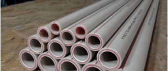
Polypropylene
A manifold made of polypropylene pipe is an extremely economical option. In addition to the affordable price, one can note the light weight of the device. Models with fittings and combs with shut-off ball valves are available for sale. To connect metal products, combined fittings are used.
The disadvantages of polypropylene collectors include:
- thick walls, due to which the passage cross-section is smaller than that of metal combs of the same size;
- less strength and durability compared to metal models;
- oxygen permeability - even if polypropylene is reinforced with fiberglass reinforcement, there is diffusion of oxygen, which provokes corrosion of steel elements of the heating system and boiler.
Collector block made of polypropyleneSource chudopol.ru
The list of advantages of polymer combs includes:
- resistance to aggressive environments (antifreeze can be used as a coolant);
- resistance to electrochemical corrosion;
- low heat loss compared to metal products.
You can buy a polypropylene heating manifold or make it yourself from a pipe of a suitable size and fittings.
Brass
Brass is a classic material for the manufacture of heating manifolds. The comb is made using the stamping method or holes are drilled for bends and threads are cut on sections of a hollow brass rod.
Collectors made of this material have one drawback - zinc is washed out of the metal. Therefore, it is recommended to use nickel or chrome plated products. These combs:
- durable;
- resistant to corrosion and aggressive environments.
The disadvantage of brass manifolds is their high price. You can also note the smaller flow area compared to steel models.
Brass manifoldSource prom.st
Stainless steel
Stainless steel collectors are in demand due to the combination of high performance parameters and affordable prices. The advantages include:
- large flow area, making it easier to balance the underfloor heating system;
- mechanical strength even in the presence of a weld;
- resistance to corrosion and aggressive environments;
- durability.
A heating comb of a reputable brand (for example, VALTEC), made of high-quality stainless steel, is designed for 30-50 or more years of operation. Cheap products from unknown manufacturers, including counterfeits, are often made of low-quality steel and are susceptible to corrosion.
Stainless steel manifoldSource termo-snab.ru
Mixing unit
The mixing unit can be used without a collector.
The mixing unit is often included in the collector group. Its operating principle is based on combining the supply and return flows. After passing through the heated floor loop, the medium usually has a temperature of about 30 degrees; at the mixing unit it flows into the supply flow, which allows you to get a comfortable temperature of 40 degrees.
There are many options for implementing this unit: using a three- or two-way valve, using thermostatic valves, etc. Mixers can also be prefabricated or factory-made.
The mixer usually has a thermostatic valve that measures the temperature of the medium. It is equipped with an overhead or cap sleeve. The first is simply glued to the pipe, the second is inserted into the line itself.
A three-way valve with a thermal head is installed in front of the pump. It is also useful to install a coarse filter on the supply before it.
- A three-way valve is installed on the supply side; using a thermostatic head, the element allows you to control two flows. There are mixing valves and distribution valves. The first one receives two streams from different sources, combines them into one and sends them along the required highway. The distribution valve receives one flow, which is distributed through several circuits. These elements are used not only to regulate the temperature of the coolant, but also to protect the boiler to prevent idling and overheating. However, the valve installation and layout will not be the same as when used in combination with a manifold.
A mixer with a two-way valve; on the bypass it is useful to install a hidden valve under a hexagon instead of an element with a handle.
Bypass is a channel between the return and supply combs; it creates a small circle and prevents the pump from working at a dead end when one of the lines is closed.
- The two-way valve is equipped with a thermostatic head and controls the flow in only one direction. When using this element in a mixing unit, an additional bypass valve will be required. In most cases, shut-off valves are placed under the hexagon. Ball valves cannot be used on this unit due to the impossibility of precise adjustment; it is also not recommended to install a valve with a handle, since someone could accidentally mess up the entire system setting.
The mixing unit is installed after the collector. A pump is placed between the collector and the boiler, which ensures movement in a small circle. The three-way mixing valve is installed on the supply line, the distribution valve - on the return line.
Location of two-way and three-way valves in the heating system
| Task | Two way valve | Three-way valve (distribution) | Three-way valve (mixing) |
| Boiler protection | — | Innings | Return |
| Temperature regulation | Innings | Return | Innings |
The mixing unit on a two-way valve can always be distinguished from a three-way valve by the presence of a valve on the bypass.
Adjusting the operation of the mixer using the example of a two-way valve
In a three-way valve, the flow is always open: if one plug closes, the other opens. In a mixer with a two-way shut-off device, only one plug closes; it works as follows: the thermal head determined that the temperature of the medium is lower than necessary, pressed the rod, the valve opened, and a portion passed into the manifold, mixing with the liquid from the return. When the temperature has reached the required values, the thermal head begins to close: the flow from the supply decreases, the flow from the bypass increases.
- The longer the heating circuit of the floor, the more the bypass valve is closed.
The bypass valve has a hidden valve for a hex key. When setting up the system, you need to close the thermostatic valve and open the balancing valve. The rotameters are adjusted, then the valve on the bypass is gradually closed until the rotameter rod begins to show that the coolant is becoming less. Fully open the thermostatic valve and tighten the balancing valve again. As soon as the rotameter plates lower or rise when turning the key on the bypass valve, balancing stops.
Installation
Do-it-yourself installation of infrared heated floors under laminate
Installation of a heated floor comb most often involves the assembly of a plastic or polypropylene structure. All sections of the comb must be connected to each other. The mixing unit of the pump with the valve is screwed to them. Next, thermometers and taps are installed. The technician must also install air vents.
If polypropylene is used, it is necessary to purchase tees and pipe sections of the appropriate diameter. The blanks are cut in advance. They will serve as connecting nipples. With their help, tees are connected into a single system. They cannot be connected directly.
If the property owner created the heating system himself, then he can also install a comb for it. At the same time, the warm floor will work for a long time and efficiently.
Do you need a hydraulic gun?
A hydraulic separator (hydraulic arrow) is a device that is usually placed between the boiler and the collector; it provides zero resistance in this area. Visually, the element is a hollow pipe with 4 pipes: on one side, two are intended for the boiler, on the other, for the collector. The question of installing a hydraulic separator arises when there is a need to install more than 4 pumps and more than 1 boiler.
The hydraulic arrow can be fixed vertically or horizontally, it does not matter. The first option is often chosen, as it simplifies the installation of the air vent in the upper part. A tap can be attached to the bottom to remove sludge.
Often in articles this device is attributed properties that it does not possess. We list the tasks for which you should not buy a hydraulic gun.
- Does not increase boiler efficiency
- Does not reduce fuel costs
- Does not protect against heat stroke
- You still need to select pumps for each circuit separately.
- Not intended for air bleeding or sludge protection.
The hydraulic arrow can worsen the operation of the system if the pumps are incorrectly selected. For example, a boiler unit is much inferior to the total power of devices on other circuits. As a result, the coolant reaches the comb already cold due to mixing with the reverse flow.
Are a manifold and mixing unit required?
In a small house, a heated floor may not take up so much, in which case the costs of a collector and mixer will not be worth it. The simplest solution would be to install a heated floor with one or two circuits, controlled by a TSG thermal head or an RTL tap. Regulation in this circuit occurs by limiting the temperature on the return flow.
The RTL valve is not intended for installation on a manifold; it has high hydraulic resistance. Due to the large size of the head, it is inconvenient to screw the element onto a distribution unit with a large number of adjacent circuits. This also makes it impossible to use built-in plumbing cabinets. It is not recommended to install RTL cranes on a circuit longer than 70 meters. The thermal head is usually placed in a plastic box that is hung on the wall.
The TSG head also limits the return flow, but has a Eurocone, so it can be installed on the return of the manifold. The actuator acts on the stem, and not on the valve itself. In this case, the head is occupied by the working valve of the manifold, because of this, installation of the servo drive becomes impossible. The absence of resistance makes it possible to install a longer circuit.
Comb selection
When choosing a comb, you need to know the need for its functionality and performance; it must have a reserve so that it can withstand sudden changes in pressure.
In addition, you need to consider:
- Material: Available in brass, plastic and stainless steel. The budget comb is made of plastic, but it is not durable. A welded stainless steel product is durable, but susceptible to corrosion. Brass manifolds are the highest quality and most reliable, but they are expensive.
- The number of valves for connecting the floor circuits - it is better to install a comb with a number of outlets equal to the floor branches. If there are more taps, then the extra ones will have to be plugged.
- Level of automation - There is now equipment that connects to thermostats and programmable controllers. They simplify the process of adjusting and monitoring temperature and coolant flow.
When purchasing a distribution unit, it is better to take a product from a well-known company, even if its price is higher - it will pay for itself during operation. Availability of appropriate warranty documentation for the product is mandatory.
Work progress
- We install the mixer on the return comb, if an assembled factory element is used, and tighten the union nut (American) with a wrench.
- A mixer is installed on the child’s feed using the same principle.
- We install air vents for return and supply.
- Plugs are installed at the ends opposite from the mixer; they should be tightened with a wrench.
- A drain valve is installed on the comb; it is usually located under the air vent; they are designed to bleed gases from the manifold.
- For convenience, you can screw the fitting into the comb separately and then install the tap on it.
- A pump is attached between the return mixer and the supply comb.
- The fastening element is assembled; all manufacturers have their own in the form of runners or strips. If a homemade manifold is used, then the fasteners are made from improvised materials. The holders are first mounted on the combs and only then on the wall.
- The combs should be at the same distance from each other so that they are parallel on the wall. This is not a technical requirement, but more of an aesthetic consideration. To align the combs, they are first fixed to the fasteners on one side, then the same distance is measured from the other end. This is easy to achieve in short manifolds. Typically, for many manufacturers, the standard distance between combs should be 21.5 cm.
- In practice, from the point of view of system operation, it does not matter which comb is on top. In most cases, a supply distributor is placed there, but nothing will change if you put it below. The main thing is not to confuse the supply and return rotameters.
- The plug is removed from the factory return mixing unit, the thermostatic head is screwed to it, and the measuring sleeve is inserted into the supply comb mixer.
- Two mounting strips are fixed to the wall. Fasteners and hardware are selected depending on the base material. It is advisable to fix the collector at 4 points.
- The connection is made using a Eurocone. A nut is put on the pipe, then a ring, and a thrust bushing is placed in the hole. Fixation is carried out using two keys. One fixes the hexagon, the other tightens the nut. You need to do this carefully so as not to rip off the fitting.
- The contours are drawn in increments of 100 mm.
- Installation of the circuit is completed by connecting the line to the return comb. Pipes must be placed in an insulating casing. The system is filled through drain and fill valves. The ball valves on the manifold are closed.
How to make a device yourself
Making a distribution unit yourself is not too troublesome and not at all expensive, so this option is increasingly being chosen by home craftsmen who want to save money on purchasing such an expensive device.
Drawing up a drawing
Before you begin assembling the comb with your own hands, you need to draw up a competent drawing or diagram of such a device, taking into account the number of circuits, load and other basic parameters.
A pre-compiled assembly diagram for the distribution unit allows all work to be done correctly, with the highest quality and speed.
Selection of the required material
To make a comb with your own hands, you will need to purchase a few of the simplest parts presented:
- ½ inch brass tee - four pieces;
- ball valve with a ½-inch threaded connection - five pieces;
- silicone sealant;
- standard ½" plug.
The purchased tees must have a configuration in which there is an internal thread on one side of the product, and an external thread on the opposite side.
Manufacturing
The sequence of self-manufacturing of a distribution comb for a “warm floor” heating system:
- Assemble the tees into a single line. To connect each subsequent tee to the previous one, external and internal threads are used, which allows you to get a straight pipe with side branches. Reliable sealing of all connections involves treating the threaded connections with silicone sealants applied to the external threads. All excess sealant must be removed using a rag.
- A standard tap is installed on the inlet part of the resulting straight pipe using silicone sealant and a threaded connection.
- A plug is installed on the opposite side of the base on a homemade comb.
- All side branches are provided with screwed and sealed taps. It is quite possible to make a structure for any number of taps with your own hands
The homemade distribution comb obtained in this way is perfect for arranging a four-circuit “warm floor” system.
An equally popular option is to independently solder the comb using conventional and additional fittings. The number of tees is selected individually, and the sections of PPR pipes must have a diameter similar to them. With this option, cut pipes serve as connecting nipples for joining tees.
Heating a room using a modern and highly efficient “warm floor” system is one of the most practical options in terms of saving energy resources and uniform distribution of thermal energy. When installing this type of heating over a large area, it is mandatory to use a special comb with manual or automatic control.
The use of automation in the comb control system is an ideal option that allows you to obtain the maximum level of economic benefits when consuming thermal energy. However, such a device belongs to the category of non-public and inertial, so warming up and cooling of the underfloor heating system will take some time.
Video description
How and why to bleed air from the circulation pump.
A decrease in coolant temperature may depend on the following:
- Usually, when considering pumps for a warm water floor, it is assumed that the characteristics are taken for a temperate climate, typical of the European part of Russia. If we are talking about a region with colder conditions, then the coolant will cool faster. The power reserve of the device should be greater the further north it is planned to be used. Usually it is enough if it is 25%-30%.
- The longer the pipes for underfloor heating, the greater the difference between the initial and final temperatures. If there are several circuits in the house, each of them must be considered.
- Having good insulation prevents heat leakage. The smaller it is, the weaker the coolant cools during operation. For example, when the floor was made with technological violations, the temperature decrease can become significant.
If a pump is installed, it increases the speed of water flow. As a result, the heat distribution will be more uniform in each floor contour.
You need to consider what kind of power supply is needed for the purchased device. In this regard, the most common are those designed for 220 V. If the motor runs on a three-phase voltage of 380 V, it is more efficient and reliable. However, this pump can operate on a warm floor only where such a network is available.
Dry rotor pumps Source teplowood.ru
Optimal temperature parameters
The preferred temperature of the heated floor is selected according to individual needs. After all, some people like invigorating freshness in the house, while others want to bask in the warming energy flows. However, there are generally accepted standards for the preparation of coolant, heating of floor coverings and, accordingly, indoor air. They are determined by sanitary and technological requirements. These standards have already been mentioned here, however, let us briefly recall:
- The optimal floor surface temperature is 28 0 C;
- if the room is designed for a long stay of residents or there are other heating sources, then it is advisable to reduce the temperature to 22-26 0 C - this energy regime is optimal from a medical point of view. In addition, heating of the coatings is unnoticeable upon bodily contact with them, which does not cause tactile discomfort;
- for rooms where the heat supply is the only source of heating, and also where residents are present only periodically (bathroom, toilet, hallway, loggia, covered veranda), the surface temperature of the floor covering can be raised to 32 0 C.