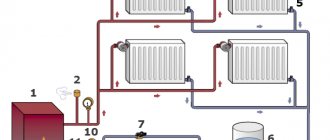
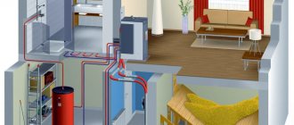
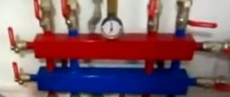
The use of this type of heating, such as a heating system with natural circulation, is most common for country houses and cottages. Its advantages are availability, cost-effectiveness, ease of installation and operation. Creating a heating system with natural circulation does not require the use of pumps or additional equipment or power sources, since hydrostatic pressure arises spontaneously during the movement of the coolant.
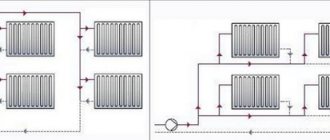
Heating scheme with natural circulation
Many consider the disadvantage that the use of this system is permissible only in fairly small buildings. In particular, the radius of the system (horizontal arrangement) should not exceed 30 meters. In addition, not everyone prefers to use heating without a pump, since the network turn-on speed is also quite low.
Main types of gravity heating system
There are 4 types of self-circulating structures with gravitational coolant flow. The choice of option depends on the owner’s requirements for heating performance, building material, insulation of the house and other nuances.
When determining which is best for water heating in a private house without a pump, you need to perform several calculations, take into account the technical characteristics of the heat source, calculate the diameter of the pipe and draw up a project
Closed system
The operating principle is as follows:
- Heating of the coolant leads to the displacement of water from the heating circuit. Under the influence of increased pressure, the liquid moves into a closed expansion tank with a membrane.
- In this tank, one half is filled with gas, the other is empty. The empty half is filled with heated coolant, which leads to compression of the gaseous substance.
- As soon as the water cools, the gas expands again and pushes water out of the tank.
A simple solution has not yet gained popularity, but the possibility of complete autonomy and maintaining optimal pressure in the pipes are clear advantages of the option that will be useful to owners of small private houses. The disadvantage of the design is that it increases the volume of the tank when it is necessary to heat large rooms, so the closed system is mainly used in houses with an area of up to 40 m2.
Open system
This option differs from a closed expansion tank only in the design. The diagram can be seen in old buildings, where the tank is installed under the roof or ceiling of the living space. You can make the container yourself, but with this design there is a risk of airing the radiators, which reduces the efficiency of the system. In addition, oxygen in water leads to the formation of corrosion, the appearance of defects inside pipes and rapid failure of elements.
Two-pipe system
Design Features:
- 2 pipes are laid - one for coolant supply, the second for return. The supply pipeline is connected by the inlet branch, the return line is connected to the tank and battery.
- The two-pipe scheme of heating systems in a private house with natural circulation ensures uniform distribution of heat throughout the room.
- There is no need to add battery sections located far from the tank to ensure the room is warmed.
- Pipes of a smaller diameter are selected for the circuit; it is much easier to regulate the intensity of the coolant supply and the heating level.
In a 2-pipe system, some deviations from the pipe slope parameters can be allowed, and this will not affect the speed of coolant transportation. The work can be completed by a home craftsman; errors in calculations are eliminated during the process of arranging the structure.
Single pipe system
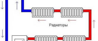
This is a simple horizontal layout with one pipe, which is connected in series to all batteries. The supply of media through the upper outlet is outflow through the lower one, so the second battery receives a slightly cooler medium, the third - even cooler. From the outermost radiator, the return flow returns to the tank for heating.
Setting up such a gravity-flow system is not difficult, but if the number of radiators is more than 3-5, a single-pipe system is not advisable. Even if you increase the number of sections of the last battery, the temperature of the carrier is too low to ensure uniform heating.
The advantages of the scheme include ease of installation, cost savings, and the disadvantage is observed only when installing one pipe in large rooms. It is impossible to create a single-pipe scheme in 2 or more storey buildings without a pump - there is a high risk of making a mistake in the slopes of the pipelines, as a result of which the coolant will not be transported at the required speed, and the building will be left without heating.
The principle of operation of heating systems with natural circulation
The gravity heating system of a private house is organized taking into account physical laws. The difference between the density and weight of the heated and cooled liquid contributes to the natural flow of coolant in the network. There is practically no pressure in the circuit and is only 0.5-0.7 atmospheres.
Since the volume of liquid increases during the heating process, an expansion tank is installed in the circuit. Its main purpose is to balance the pressure in the system. Excess expanded liquid enters this container, and when the pressure in the network decreases, water from the tank passes back into the pipelines. The expansion tank is installed at the highest point of the network after the accelerating vertical riser.
Heated floors can be connected to the gravity circuit. In this case, it is necessary to install pumping equipment only on the pipeline in the floor, and the coolant will circulate naturally in the distribution of heating devices.
Also, the gravity circuit can be used in conjunction with an indirect heating boiler. This equipment is installed at the highest point of the wiring, but below the expansion tank. In this case, you do not have to use pumping equipment. If such a scheme cannot be used, then the pump is mounted only on a storage tank. In this case, a check valve must be installed to protect against recirculation of the coolant.
Important! In gravity circuits, it is necessary to slope the pipeline with the return towards the boiler to ensure the movement of cooled liquid.
Advantages and disadvantages of a single-pipe system
Single-pipe heating has gained wide popularity in the field of private construction.
The main reasons are the relatively low cost of the structure and the ability to install it on your own, without the involvement of specialists.
But a single-pipe heating system has other advantages:
- Hydraulic stability - the heat transfer of other elements of the system does not change when individual circuits are disconnected, radiators are replaced or sections are expanded;
- The construction of the main line requires a minimum number of pipes;
- It is characterized by low inertia and warm-up time due to the smaller amount of coolant in the line than in a two-pipe system;
- It looks aesthetically pleasing and does not spoil the interior of the room, especially if the main pipe is hidden;
- Installation of the latest generation shut-off valves - for example, automatic and manual thermostats - allows you to precisely adjust the operating mode of the entire structure, as well as its individual elements;
- Simple and reliable design;
- Easy installation, maintenance and operation.
When connecting control and monitoring devices to the heating system, it can be switched to a fully automatic operating mode.
Integration with the Smart Home system is possible - in this case, you can set programs for optimal heating modes depending on the time of day, season and other decisive factors.
A single-pipe heating line can be completely hidden with finishing. Such a device not only does not spoil the appearance of the room, but also becomes its detail - an interior item.
The main disadvantage of single-pipe heat supply is the imbalance of heating of heat-transfer batteries along the length of the main line.
The coolant cools as it moves along the circuit. Because of this, radiators installed far from the boiler heat up less than those located close to them. Therefore, it is recommended to install slowly cooling cast iron appliances.
Installing a circulation pump allows the coolant to warm up the heating circuits more evenly, however, if the pipeline is of sufficient length, significant cooling is observed.
The negative effects of this phenomenon can be reduced in two ways:
- In radiators remote from the boiler, the number of sections is increased. This increases their heat-conducting area and the amount of heat given off, allowing rooms to be heated more evenly.
- They draw up a project with a rational arrangement of heat-emitting devices in the rooms - the most powerful ones are installed in children's rooms, bedrooms and “cold” (northern, corner) rooms. As the coolant cools down, the living room and kitchen proceed, ending with non-residential and utility rooms.
Such measures minimize the disadvantages of a single-pipe system, especially for one- and two-story buildings with an area of up to 150 m². For such houses, single-pipe heating is the most profitable.
How to embed a pump
To facilitate the process of installing the pump in the heating system, it is necessary to buy a pump with a detachable thread. To perform the work efficiently, we will need the following equipment:
- Ball valves selected according to the diameter of the pipeline;
- Keys of the required size;
- Sealant;
- Fasteners, connecting elements;
- Automatic valves.
After selecting all the necessary equipment, we proceed to selecting a site for installing the circulation pump. If previously pumps were installed in the return pipeline, which made it possible to extend the service life of the device in question, now this equipment is made with water-resistant parts. In this regard, the pump can be installed both on the supply and return pipelines.
Note! In order to increase the pressure in the system, the pump is installed on the supply pipe in close proximity to the expansion tank. In the “Warm Floor” system, to prevent the formation of air accumulations, the pump is mounted in the area where the heated coolant is supplied.
When installing the pump in the heating system, you need to pay attention to one important detail. The device in question may fail after exhausting its service life, therefore, for quick replacement without draining water from the heating system, ball valves are mounted on both sides of the installation. To protect the pump from destruction, a mesh filter is installed in front of the entrance, which will trap abrasive particles present in the water.
To release accumulated gases, a manual or automatic valve is installed at the top of the bypass. The pump terminals should be oriented upward, which will prevent the possibility of a short circuit when water drains from the device. This phenomenon often happens when the pump breaks down. Each connection is coated with sealant, and special rubber gaskets are installed at the threaded connections.
Rules for installing a heating system without a pump
All gravity schemes have one drawback - there is no pressure in the system, therefore violations in installation lead to a decrease in the functionality of the structure. The work is affected by turns, high or low slopes, and the lack of a well-thought-out scheme.
To form the correct heating system, you should pay attention to:
- laying out slopes;
- type, pipe diameter;
- supply, type of coolant.
Selection of pipes and their slope in the heating system
There are several types of material suitable for pipeline construction:
- Steel. These are pipes with a relatively low cost, but increased thermal conductivity and strength. Steel tolerates pressure differences well and resists corrosion. Minus - welding will be required.
- Metal-plastic. Pipes with a smooth inside to minimize blockages. Light weight and linear expansion are advantages, short service life (15 years) and high price are disadvantages.
- Polypropylene. Simple installation, tightness, durability, long service life and resistance to freezing are the advantages of pipes, but the price of the product is a minus. It should be taken into account that joining is carried out by soldering, which reduces installation costs. Service life up to 25 years.
- Copper. An extremely durable material that can withstand heating up to +500 C. A service life of 100 years, extreme resistance to corrosion are advantages. But the very high price and weight are obvious disadvantages of pipelines.
As for the choice of diameter, it needs to be calculated as follows:
- take into account the room’s need for thermal energy and add 20% to the final figure;
- according to SNiP, find the parameters of the ratio of the power of the heating network to the internal cross-section of the pipe;
- select the material from which the pipes are made from the table, take into account the standard parameters, in particular, for steel pipes the diameter should be at least 50 mm, but when selecting wide pipes, the efficiency of the coolant decreases.
As for the slope, according to building codes, for each linear meter of pipe you need to make a slope of 10 mm. These standards must be taken into account when planning gravity heating, and the layout diagram, previously drawn up in the form of a project, will help measure the installation parameters during installation work.
Selecting a coolant for the system
In order for natural circulation in the heating system of a private home to be maintained at the required speed, the optimal coolant should be selected. In most cases, clean water is chosen - a safe and cheap option. Antifreeze can be used, but higher density and lower heat transfer neutralize the advantages of the liquid. Glycol formulations are needed only under the condition that the heating system will not be used for a very long time, antifreeze does not freeze, and, unlike water, does not burst pipes.
https://youtube.com/watch?v=vVEj7wcr1ik
Choice of top or bottom spill
If bottom filling is used, the pipeline is laid at the level of the floor covering. When forming a single-pipe gravity flow scheme, the bottom filling is considered not thermally efficient; the scheme is justified for pipelines with high coolant pressure.
Top filling is better suited for private buildings. In this case, a hot stream is supplied through a pipe under the ceiling, the water displaces air, which can be vented with a Mayevsky tap. With top filling, you can use a single-pipe heating circuit; in this case, the thermal efficiency is maintained at optimal values.
Knowing how to circulate water without a pump, you should be careful about all stages of design and installation. Errors in operation lead to the reinstallation of all elements, modification of the circuit or installation of the pump, and this increases financial investments.
Rules for the selection and installation of pipes
The choice between steel or polypropylene pipes for any circulation is made according to the criterion of the possibility of their use for hot water, as well as from the standpoint of price, ease of installation and service life.
The supply riser is mounted from a metal pipe, since water of the highest temperature passes through it, and in the case of stove heating or a malfunction of the heat exchanger, steam can pass through.
With natural circulation, it is necessary to use a pipe diameter slightly larger than when using a circulation pump. Typically, for heating rooms up to 200 square meters. m, the diameter of the acceleration manifold and the pipe at the return inlet to the heat exchanger is 2 inches.
This is caused by a lower water velocity compared to the forced circulation option, which leads to the following problems:
- reduction in the volume of transferred heat per unit time from the source to the heated room;
- the appearance of blockages or air pockets that a small pressure cannot cope with.
When using natural circulation with a bottom supply circuit, special attention must be paid to the problem of removing air from the system. It cannot be completely removed from the coolant through the expansion tank, because Boiling water first enters the devices through a line located lower than themselves.
With forced circulation, the water pressure drives air to an air collector installed at the highest point of the system - a device with automatic, manual or semi-automatic control. With the help of Mayevsky taps, heat transfer is mainly adjusted.
In gravitational heating networks with a supply located below the devices, Mayevsky taps are used directly for bleeding air.
All modern heating radiators have devices for releasing air, therefore, to prevent the formation of plugs in the circuit, you can make a slope, driving air to the radiator
Air can also be removed using air vents installed on each riser or on an overhead line laid parallel to the system mains. Due to the impressive number of air exhaust devices, gravity circuits with bottom wiring are used extremely rarely.
With low pressure, a small air lock can completely stop the heating system. Thus, according to SNiP 41-01-2003, it is not allowed to lay heating system pipelines without a slope at a water speed of less than 0.25 m/s.
With natural circulation such speeds are unattainable. Therefore, in addition to increasing the diameter of the pipes, it is necessary to maintain constant slopes to remove air from the heating system. The slope is designed at the rate of 2-3 mm per 1 meter; in apartment networks, the slope reaches 5 mm per linear meter of the horizontal line.
The supply slope is made in the direction of water movement so that the air moves to the expansion tank or air bleed system located at the top point of the circuit. Although it is possible to make a counter-slope, in this case it is necessary to additionally install a valve for air removal.
The slope of the return line is usually made in the direction of movement of the chilled water. Then the lowest point of the circuit will coincide with the entrance of the return pipe to the heat generator.
The most common combination of supply and return pipe slope directions for removing air pockets from a natural circulation water circuit
When installing a heated floor of a small area in a circuit with natural circulation, it is necessary to prevent air from entering the narrow and horizontal pipes of this heating system. It is necessary to install an air removal device in front of the heated floor.
Heating with water as coolant
The functional features of water heating systems with a natural type of coolant circulation are determined by a number of characteristics.
Based on which expansion tank is used to equip a heating system with natural coolant circulation, there are:
- Open systems. In this case, the expansion tank is installed as high as possible in order to create excess pressure in the expansion tank. In addition, thanks to this you can get rid of air pockets in the heating circuit. From time to time, water that has partially evaporated during heating operation is added to the pipes through an open expansion tank.
- Closed systems. In such heating with natural circulation, the expansion tank is replaced by a special membrane hydraulic storage cylinder. It provides additional pressure in the circuit within 1.5 atmospheres. For safety reasons, systems of this design are usually equipped with a block with a pressure gauge, the task of which is to adjust the pressure inside the pipeline.
Another fundamental point that distinguishes the design of heating systems with a natural type of water circulation is the connection diagram of the heating elements.
According to the method of connecting heating devices to a gas boiler without a pump, the following options can be distinguished:
- Single-pipe heating distribution. With this type of heating, all radiators are connected in series to the same pipe. That is, water passes through each subsequent heating device and only after that it moves on. Among the advantages of single-pipe distribution equipment are the simplicity of its installation, as well as low material consumption.
- Two-pipe wiring in a heating system with a natural circulation type. In this case, all radiators that are part of the heating system are connected to the pipeline in parallel. In this case, the temperature of the coolant that enters each radiator is the same. After the water has passed through the entire radiator and cooled, it returns through the return pipe to the boiler heat exchanger.
It is believed that a two-pipe wiring diagram is the most appropriate from the point of view of the efficiency of heating a home. True, to equip such a system, you will need quite a lot of pipes and additional elements for installing the heating circuit.
Conclusions and useful video on the topic
Organization of a single-pipe circuit based on an electric boiler for a small house:
Operation of a two-pipe system for a one-story wooden house based on a long-burning solid fuel boiler:
The use of natural circulation during the movement of water in the heating circuit requires accurate calculations and technically competent installation work. If these conditions are met, the heating system will efficiently heat the premises of a private house and relieve the owners from pump noise and dependence on electricity.
If you have any questions on the topic or would like to share your personal experience in organizing and operating a gravity-type heating system, please leave comments on this article. The feedback block is located below.
Rules for calculating tank capacity
Any type of dilator will be effective only if the volume is chosen correctly. To do this, take into account the ability of the liquid to expand during the heating period. Water in heating rings expands by at least 3% of the total volume of the water system, antifreeze - by almost 5%.
Liquids belong to the category of incompressible media, so the tank must provide them with a sufficient reserve for thermal expansion with some margin. Provided that the circuit is completely filled with coolant, even thermal expansion in the calculated volumes can lead to liquid discharge through the safety valve and spillage of coolant onto the floor.
Therefore, so that exceeding the volume of expanding coolant does not lead to accidents, closed tanks for small circuits in private houses are purchased so that their volume is equal to 10% of the total volume of coolant circulating through the system. This rule is valid for systems with a capacity of up to 150 l.
If more than 150 liters of coolant moves along the heating ring, then the capacity of a closed tank is calculated by multiplying the total volume of liquid by its expansion coefficient at specific operating temperatures in the system.
To the obtained value you need to add the size of the water seal, i.e. the volume of coolant formed in the tank as a result of standard static fluid pressure. For large heating rings, this figure is usually equal to 0.5% of the total coolant volume; for small ones, with a capacity of up to 150 liters, it is taken to be 20%.
The resulting amount is multiplied by a correction factor determined from the values of preliminary and final pressure in the heating system. The preliminary estimate is that there is 1 bar per 10 m of contour height. The final pressure is formed as a result of the operation of the system.
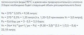
Calculation of the volume of a closed tank for large complex heating structures looks like this:
The calculations used: Vn – nominal volume of a closed tank; Ve is the volume of the coolant during thermal expansion (calculated using the formula Vsystem×n%, where n is the coefficient of thermal expansion of the coolant); Vv – water seal; po – preliminary pressure; pe – final pressure indicator, equal to the maximum pressure value of the safety valve minus 0.5 bar
Open type capacity is not strictly regulated by regulations, but there is a rule: the volume of the open tank to the overflow pipe should be 3.5 - 4% of the total volume of coolant in the heating circuit.
This estimate is sufficient for a small country house, but a building for permanent residence will require a more accurate calculation. First of all, you will need to find out the total volume of the heating system.
Options for calculating the total heating capacity
This indicator can be determined with varying degrees of accuracy in three main ways. Firstly, based on the boiler’s passport data. Thus, about 15 liters of liquid are needed per unit of boiler equipment power. To obtain the necessary data, you will need to multiply 15 by the boiler power indicated in the data sheet.
Secondly, you can find out the volume using a water meter when filling the system. As you fill, the amount of liquid used is taken into account. This is a more accurate and troublesome option.
The third method involves calculating the total volume of all elements of the heating system. This is the most accurate option. The capacity of the heat exchanger of the boiler, radiators, convectors, and measuring instruments can be determined from the passport characteristics. To calculate the pipe capacity, data from the table is used.
The table shows the pipe sizes in inches and their volume in liters per 1 meter, which is used to summarize the total volume
The table shows the volume of pipes per meter of length, made from the most popular and modern materials. The internal diameter is indicated in inches from 0.5 to 1.5 units.
Another method that claims to be highly accurate is calculation using the formula:
Vtotal = π x D2 x L/4,
Where:
- π – equal to 3.14;
- D – indicates the parameters of the internal diameter of the pipes;
- L – indicates the length of the system pipeline.
After receiving the necessary data, they are summed up and the total volume of the system is obtained, which is used in further calculations.
Steps and formulas for the full cycle of calculations for designing and organizing the heating of a private home are given here. We recommend that you read the useful information.
Selecting an expansion tank according to the table
If you have the necessary data, the optimal expander option can be selected using the table of volumes and design pressure.
The total volume of the system is calculated according to the specified method; the pressure parameters are relevant only for closed modifications and are indicated in the equipment data sheet.
The data from the table allows you to select the expander volume from 4 to 300 liters
This option does not require special calculations other than calculating the total volume of the system. Using the table greatly simplifies and speeds up the selection of an expander with the required tank capacity.
Using calculation formulas
If the table data is not enough, it is possible to calculate the required capacity indicator yourself.
To do this, use the following formula:
Vb = Vc xk/D,
Where:
- Vb – denotes the desired expander capacity;
- Vc – total system capacity;
- k is the expansion coefficient of the liquid when heated;
- D – expander efficiency coefficient.
Of the data necessary for the calculation, the coefficients k and D remain unknown. The first is a tabular value, and the second is calculated using a separate formula.
A temperature expansion table also exists and is used. It allows you to determine the coefficient for systems with water or antifreeze. The value is not linear; it changes when heated, depending on the presence and concentration of glycol in the liquid.
Using these data, it is possible to determine the parameters of the coefficient of expansion of the liquid when heated (k), necessary for calculating the volume of the expansion cylinder
For water, the concentration of ethylene glycol is taken as “0”; for antifreeze, the concentration is determined according to the data declared by the manufacturer. The heating temperature is considered operational for a specific system.
To independently calculate the efficiency coefficient of the expansion tank, use the formula:
(Qm – Qb) : (Qm + 1),
Where:
- Qm is the maximum pressure of the system according to the safety valve’s nominal response threshold;
- Qb is the preliminary pressure in the air chamber of the expander according to the data sheet.
If the latter parameter is unknown, it is measured during inflation or by bleeding through the nipple of the cylinder.
Other calculation methods
In addition to independent calculations using formulas and tables, there are alternative methods. An accessible calculation option is the help of an online calculator.
There is no shortage of network resources offering online calculation of the required value. They are easy to find by keyword
Another option to obtain the necessary data is to contact professional designers. This is the most reliable way, but the accuracy of the information obtained will be quite expensive.
The following article dedicated to these issues will introduce you to the rules for installing and connecting closed and open type expanders.
Calculation of gravity system
To calculate and design heating with natural circulation, proceed in this order:
- Find out the amount of heat needed to heat each room. Use our instructions for this.
- Choose a non-volatile boiler - gas or solid fuel.
- Develop a diagram based on one of the options proposed here. Divide the wiring into 2 branches - then the lines will not cross the front door of the house.
- Determine the coolant flow for each room and calculate the pipe diameters.
Note. There is no need to calculate slopes; take the standard value of 0.5 cm per meter of length. Deviations up or down in the range of 0.7…0.2 cm/1 m are allowed.
It will not be possible to split it into 2 branches right away. This means that the ring pipeline will definitely pass under the threshold of the front door. To withstand all the slopes, the boiler will have to be placed in a pit.
The calculation of the diameter of the pipes in all sections of the gravity two-pipe system is done as follows:
- We take the heat loss of the entire building (Q, W) and determine the mass flow rate of the coolant (G, kg/h) in the main line using the formula below. The temperature difference between supply and return Δt is taken equal to 25 °C. Then we convert kg/h to other units - tons per hour.
- Using the following formula, we find the cross-sectional area (F, m²) of the main riser, substituting the value of the natural circulation speed ʋ = 0.1 m/s. We recalculate the area of the circle into diameter, we get the size of the main pipe suitable for the boiler.
- We calculate the thermal load on each branch, repeat the calculations and find out the diameters of these lines.
- We move on to the next rooms and again determine the diameters of the sections based on heat costs.
- We select standard pipe sizes, rounding the resulting numbers up.
Let's give an example of calculating a gravity system in a one-story house of 100 square meters. The layout below already shows heating radiators and indicates heat losses. We start from the main boiler manifold and move towards the last rooms:
- The amount of heat loss at home is Q = 10.2 kW = 10200 W. Coolant flow in the main riser G = 0.86 x 10200 W / 25 °C = 350.88 kg/h or 0.351 t/h.
- The cross-sectional area of the supply pipe is F = 0.351 t/h / 3600 x 0.1 m/s = 0.00098 m², diameter d = 35 mm.
- The load on the right and left branches is 5480 and 4730 W, respectively. Amount of coolant: G1 = 0.86 x 5480 / 25 = 188.5 kg/h or 0.189 t/h, G2 = 0.86 x 4730 / 25 = 162.7 kg/h or 0.163 t/h.
- The cross section of the right branch is F1 = 0.189 / 3600 x 0.1 = 0.00053 m², the diameter will be 26 mm. Left branch: F2 = 0.163 / 3600 x 0.1 = 0.00045 m², d2 = 24 mm.
- Lines DN32 and DN25 mm (rounded up) will come to the nursery and kitchen. Now we calculate the sizes of collectors for the bedroom and living room + corridor with heat losses of 2.2 and 2.95 kW, respectively. We get both diameters DN20 mm.
To connect small batteries, you can use DN15 connections (outer d = 20 mm), the plan shows DN20 dimensions
Attention! The diameters obtained as a result of calculations indicate the size of the internal passage of pipelines (designation - DN or DN).
All that remains is to pick up the pipes. If you make heating from steel, the boiler riser will be Ø48 x 3.5, the branches will be Ø42 x 3 and 32 x 2.8 mm. The remaining wiring, including connections to the batteries, is done with a 26 x 2.5 mm pipeline. The first digit of the size indicates the outer diameter, the second - the wall thickness (range of water and gas steel pipes).
Features of the heating system in a private house
Systems of this type have some features, in particular we are talking about the following:
The following factors influence the circulation pressure:
- Height distance between the boiler and the lower radiator. The principle of communicating vessels works here: water flows faster into a boiler located lower in relation to the lowest heating device. This parameter remains unchanged throughout the entire system operation.
- The different density of water at the outlet of the boiler and in the return pipe, determined by the temperature of the water. Thanks to this factor, self-regulation occurs: as the air temperature in the room decreases, the radiators also cool down. This leads to an increase in the density of the coolant and faster displacement of heated water.
Connection diagrams for heating devices
Rice. 16. Some diagrams for connecting heating devices
Rice. 17. Wiring for radiators of the heating system
Rice. 18. Wiring diagram for a cast iron radiator
Rice. 19. Installation diagram of cast iron radiators
Single-pipe horizontal
The simplest version of a single-pipe horizontal heating system with a bottom connection.
When creating a heating system for a private house with your own hands, a single-pipe wiring diagram may turn out to be the most profitable and cheapest. It is equally suitable for both one-story and two-story houses. In the case of a one-story house, it looks very simple - the radiators are connected in series to ensure consistent flow of coolant. After the last radiator, the coolant is sent through a solid return pipe to the boiler.
Advantages and disadvantages of the scheme
First, we will look at the main advantages of the scheme:
- ease of implementation;
- excellent option for small houses;
- saving of materials.
A single-pipe horizontal heating circuit is an excellent option for small spaces with a minimum number of rooms.
The scheme is really very simple and understandable, so even a beginner can handle its implementation. It provides for a serial connection of all installed radiators. This is an ideal heating layout for a small private house. For example, if this is a one-room or two-room house, then “fencing” a more complex two-pipe system does not make much sense.
Looking at the photo of such a circuit, we can note that the return pipe here is solid, it does not pass through the radiators. Therefore, this scheme is more economical in terms of material consumption. If you don’t have extra money, this type of wiring will be the most optimal for you - it will save money and allow you to provide heat to your home.
As for the shortcomings, there are few of them. The main disadvantage is that the last radiator in the house will be colder than the very first one. This is due to the sequential passage of the coolant through the batteries, where it releases the accumulated heat into the atmosphere. Another disadvantage of a single-pipe horizontal circuit is that if one battery fails, the entire system will have to be turned off at once.
Despite certain disadvantages, this heating scheme continues to be used in many small private houses.
Features of installation of a single-pipe horizontal system
When creating water heating for a private house with your own hands, the scheme with single-pipe horizontal wiring will be the easiest to implement. During the installation process, it is necessary to mount the heating radiators, and then connect them with pipe sections. After connecting the very last radiator, it is necessary to turn the system in the opposite direction - it is advisable that the outlet pipe runs along the opposite wall.
A single-pipe horizontal heating circuit can also be used in two-story houses; each floor here is connected in parallel.
The larger your home, the more windows it has and the more radiators it has. Accordingly, heat losses also increase, as a result of which the last rooms become noticeably cooler. You can compensate for the temperature drop by increasing the number of sections on the latest radiators. But it is best to install a system with bypasses or with forced circulation of the coolant - we will talk about this a little later.
A similar heating scheme can be used to heat two-story houses.
To do this, two chains of radiators are created (on the first and second floors), which are connected in parallel to each other. There is only one return pipe in this battery connection diagram; it starts from the last radiator on the first floor. The return pipe coming down from the second floor is also connected there. Date: September 25, 2022
Which scheme is better, forced or natural?
A natural system is better if you need to organize heating for a small one-story private house. In this case, there is no point in spending money on pumping equipment when the natural coolant current will be sufficient to heat the entire building.
Forced circulation circuits are best used in large one-story or multi-story buildings. Thanks to the rapid movement of the coolant in the network, buildings of significant size will be heated well and evenly. Natural circulation circuits will not cope with this task.
