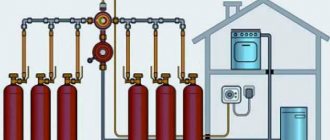
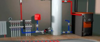
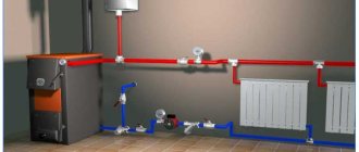
What's happened? Principle of operation
Gravity - a system based on the laws of physics, i.e. natural movement of coolant through pipes. Hot liquid rises, cold liquid falls. This heating system is most often used for a private home if there is no electricity connection or the supply is unstable.
The only limitation may be the ceiling height. Since the pipe must extend 1.5 meters upward from the boiler, space is still needed for the expansion tank. There are limitations to the system, such as the cost of creating the system and reduced efficiency. Its price is approximately 1.5 times higher than creating a simple forced heating circuit. Also required is the accuracy of installation of the system, compliance with all slopes while maintaining the appearance of the interior.
The principle of operation of a gravity heating system is the movement of liquid to the top point of this system under the influence of physical laws, when the warm liquid is lighter, rises, then the coolant moves through pipes with a slight slope, gradually giving off heat, cools down, then also by gravity to the boiler to warm up again . It does not imply any devices that accelerate the movement of water, so it is highly inert.
Rules for calculating tank capacity
Any type of dilator will be effective only if the volume is chosen correctly. To do this, take into account the ability of the liquid to expand during the heating period. Water in heating rings expands by at least 3% of the total volume of the water system, antifreeze - by almost 5%.
Liquids belong to the category of incompressible media, so the tank must provide them with a sufficient reserve for thermal expansion with some margin. Provided that the circuit is completely filled with coolant, even thermal expansion in the calculated volumes can lead to liquid discharge through the safety valve and spillage of coolant onto the floor.
Therefore, so that exceeding the volume of expanding coolant does not lead to accidents, closed tanks for small circuits in private houses are purchased so that their volume is equal to 10% of the total volume of coolant circulating through the system. This rule is valid for systems with a capacity of up to 150 l.
If more than 150 liters of coolant moves along the heating ring, then the capacity of a closed tank is calculated by multiplying the total volume of liquid by its expansion coefficient at specific operating temperatures in the system.
To the obtained value you need to add the size of the water seal, i.e. the volume of coolant formed in the tank as a result of standard static fluid pressure. For large heating rings, this figure is usually equal to 0.5% of the total coolant volume; for small ones, with a capacity of up to 150 liters, it is taken to be 20%.
The resulting amount is multiplied by a correction factor determined from the values of preliminary and final pressure in the heating system. The preliminary estimate is that there is 1 bar per 10 m of contour height. The final pressure is formed as a result of the operation of the system.
Calculation of the volume of a closed tank for large complex heating structures looks like this:
The calculations used: Vn – nominal volume of a closed tank; Ve is the volume of the coolant during thermal expansion (calculated using the formula Vsystem×n%, where n is the coefficient of thermal expansion of the coolant); Vv – water seal; po – preliminary pressure; pe – final pressure indicator, equal to the maximum pressure value of the safety valve minus 0.5 bar
Open type capacity is not strictly regulated by regulations, but there is a rule: the volume of the open tank to the overflow pipe should be 3.5 - 4% of the total volume of coolant in the heating circuit.
This estimate is sufficient for a small country house, but a building for permanent residence will require a more accurate calculation. First of all, you will need to find out the total volume of the heating system.
Options for calculating the total heating capacity
This indicator can be determined with varying degrees of accuracy in three main ways. Firstly, based on the boiler’s passport data. Thus, about 15 liters of liquid are needed per unit of boiler equipment power. To obtain the necessary data, you will need to multiply 15 by the boiler power indicated in the data sheet.
Secondly, you can find out the volume using a water meter when filling the system. As you fill, the amount of liquid used is taken into account. This is a more accurate and troublesome option.
The third method involves calculating the total volume of all elements of the heating system. This is the most accurate option. The capacity of the heat exchanger of the boiler, radiators, convectors, and measuring instruments can be determined from the passport characteristics. To calculate the pipe capacity, data from the table is used.
The table shows the pipe sizes in inches and their volume in liters per 1 meter, which is used to summarize the total volume
The table shows the volume of pipes per meter of length, made from the most popular and modern materials. The internal diameter is indicated in inches from 0.5 to 1.5 units.
Another method that claims to be highly accurate is calculation using the formula:
Vtotal = π x D2 x L/4,
Where:
- π – equal to 3.14;
- D – indicates the parameters of the internal diameter of the pipes;
- L – indicates the length of the system pipeline.
After receiving the necessary data, they are summed up and the total volume of the system is obtained, which is used in further calculations.
Steps and formulas for the full cycle of calculations for designing and organizing the heating of a private home are given here. We recommend that you read the useful information.
Selecting an expansion tank according to the table
If you have the necessary data, the optimal expander option can be selected using the table of volumes and design pressure.
The total volume of the system is calculated according to the specified method; the pressure parameters are relevant only for closed modifications and are indicated in the equipment data sheet.
The data from the table allows you to select the expander volume from 4 to 300 liters
This option does not require special calculations other than calculating the total volume of the system. Using the table greatly simplifies and speeds up the selection of an expander with the required tank capacity.
Using calculation formulas
If the table data is not enough, it is possible to calculate the required capacity indicator yourself.
To do this, use the following formula:
Vb = Vc xk/D,
Where:
- Vb – denotes the desired expander capacity;
- Vc – total system capacity;
- k is the expansion coefficient of the liquid when heated;
- D – expander efficiency coefficient.
Of the data necessary for the calculation, the coefficients k and D remain unknown. The first is a tabular value, and the second is calculated using a separate formula.
A temperature expansion table also exists and is used. It allows you to determine the coefficient for systems with water or antifreeze. The value is not linear; it changes when heated, depending on the presence and concentration of glycol in the liquid.
Using these data, it is possible to determine the parameters of the coefficient of expansion of the liquid when heated (k), necessary for calculating the volume of the expansion cylinder
For water, the concentration of ethylene glycol is taken as “0”; for antifreeze, the concentration is determined according to the data declared by the manufacturer. The heating temperature is considered operational for a specific system.
To independently calculate the efficiency coefficient of the expansion tank, use the formula:
(Qm – Qb) : (Qm + 1),
Where:
- Qm is the maximum pressure of the system according to the safety valve’s nominal response threshold;
- Qb is the preliminary pressure in the air chamber of the expander according to the data sheet.
If the latter parameter is unknown, it is measured during inflation or by bleeding through the nipple of the cylinder.
Other calculation methods
In addition to independent calculations using formulas and tables, there are alternative methods. An accessible calculation option is the help of an online calculator.
There is no shortage of network resources offering online calculation of the required value. They are easy to find by keyword
Another option to obtain the necessary data is to contact professional designers. This is the most reliable way, but the accuracy of the information obtained will be quite expensive.
The following article dedicated to these issues will introduce you to the rules for installing and connecting closed and open type expanders.
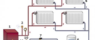
The principle of operation of the gravity system
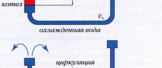
One of the principles used in the operation of the system is known to everyone from a school physics course: this is the rise of hot water and air and their descent downwards - at low temperatures.
After the water warms up in the boiler, it begins its movement up the riser. As a result, it ends up in the heating radiator, where it transfers some of its heat, thereby becoming colder than in the drain. Cooled, the water begins to move downwards and enters the next radiator. This continues until the water returns to the boiler.
Do-it-yourself installation recommendations
To lay the main natural circulation lines, it is better to use polypropylene or steel pipes. The reason is the large diameter, polyethylene Ø40 mm and more is too expensive. We make radiator hoses from any convenient material.
Advice. When assembling a gravity heating network made of metal-plastic, do not install compression fittings - they greatly reduce the internal passage.
How to make the layout correctly and withstand all the slopes:
- Start with markings. Mark the locations for installing batteries, connection points for connections, and routes for highways.
- Mark the routes on the walls with a pencil, starting from the distant batteries. Adjust the amount of inclination using a long building level.
- Move from the outer radiators to the boiler room. When you draw all the routes, you will understand at what level to install the heat generator. The inlet pipe of the unit (for cooled coolant) must be located at the same level or below the return line.
- If the firebox floor level is too high, try moving all the heaters up. Horizontal pipelines will rise next. As a last resort, make a recess under the boiler.
Laying a return line in a furnace room with a parallel connection to two boilers.
After marking, punch holes in the partitions and cut grooves for a hidden gasket. Then check the routes again, make adjustments and proceed with installation. Follow the same order: first secure the batteries, then lay the pipes towards the combustion chamber. Install an expansion tank with a drain pipe.
The gravity pipeline network is filled without problems; Mayevsky’s taps do not need to be touched. Just slowly pump water through the fill valve at the lowest point, all the air will go into the open tank. If any radiator remains cold after warming up, use a manual air vent.
Gravity heating schemes
One of the first steps when installing the heating system in question is the choice of a scheme that determines the further work process and the efficiency of the operating period.
The consequences of the choice made affect the design of the premises and the uniformity of heat distribution, ease of use, and above all, the total amount of work and the price of the materials used during installation.
Despite the presence in the virtual space of a huge number of diagrams and drawings, including videos, it is quite difficult to understand them on your own - without a specialist, and most importantly, each diagram requires its adaptation to a specific order.
There are several common wiring schemes:
- Single-pipe
- Two-pipe
- Spider
- Leningradka
The choice of scheme depends on the number of floors, area of the house, and layout. Let's consider each option separately.
Single-pipe
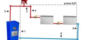
The simplest gravity heating system, but not the most efficient. The most important thing is compliance with assembly technology. The hot water riser must be without any bends, turns, joints, i.e. straight, all pipes must be located at a constant technological slope.
You can install a single-pipe system yourself. It does not require special knowledge, it just requires adherence to technology. Of course, it is impossible to avoid the presence of joints and turns, but they must be minimized. Their use reduces the efficiency of the entire system.
An important factor in heating a single-pipe gravity system is the diameter of the pipe through which the coolant moves. The larger it is, the better the circulation. For a one-pipe system, it is recommended to use a pipe diameter of at least 1 inch, with 1.5 inches being the most optimal. A larger pipe diameter means a lower level of resistance to coolant flow.
The boiler must be located at the lowest point of the system, and the hot water riser must be raised as high as possible. Pipe laying is carried out with a constant slope. It should correspond to 1 cm per meter of pipe. The slope must be constant; this is the main parameter that ensures the operability of the system.
Most schemes require the location of a hot water pipe under the ceiling, in the attic space, and a return loop above the floor. A single-pipe system involves the creation of one circuit through which water flows to the radiators and returns through the same circuit for heating.
Two-pipe
Gravity heating system based on two circuits. The first circuit departs from the main riser of a common pipe with hot liquid. All radiators are powered from it, a separate connection goes to them for each. The cooled water from the radiators and its return to the boiler is carried out through another pipe.
The two-pipe gravity system allows all radiators to be supplied with coolant at the same temperature and ensures uniform heat distribution throughout the house. You can reduce the flow of liquid through one of the radiators, which will not affect the heating of the rest of the house.
Spider
A gravity-flow system according to the Spider scheme consists of a system in which a branch runs from a common heating riser with hot liquid to each radiator separately. A large diameter pipe is used for the riser, and the branches to the radiators come with pipes of a smaller diameter
This scheme is considered the most reliable and efficient. Of course, it has certain difficulties in installation and wiring, but due to the smaller diameter of the pipes, it is easier to lay them, and it is also not necessary to do them near the ceiling of the room.
The Spider scheme uses a significant number of pipes and connections, and technically significantly complicates the project. Every connection is a risk of leakage. Savings due to diameter reduction are also offset by the length of the pipes used and the number of connections.
The return circuit to the boiler is done classically, connecting all the radiators in a circle. Here, the slope of the return pipe is also used to allow liquid to flow naturally into the boiler for heating.
Leningradka
The system built using the Leningradka principle is constructed as follows: one collector branch runs along the floor and all radiators are connected. It is also necessary to create an accelerating loop, i.e. raising the single collector when moving away from the boiler, then returning to the floor level and then maintaining the slope from supply to return.
The Leningradka gravity system has advantages: reliability, fewer materials. Disadvantages: limited number of radiators, the need for an increased diameter of pipes, lazy flow of liquid into the radiator.
A limited number of radiators are used, because when connected by the Leningradka circuit, heat is given off by the first radiators, the cooled liquid flows back into the common collector, which reduces the temperature of the common coolant. The lazy flow of liquid to the radiator significantly reduces the efficiency of each radiator, since it is not 100% filled, it is impossible to use the efficiency of this radiator at 100%. And this scheme cannot be done with 2 branches.
Features of heating with heated air for industrial and production facilities
The organization of air heating combined with ventilation in private residential buildings differs from the implementation of air heating systems for industrial real estate - warehouses, workshops, hangars, repair shops, etc. These differences are associated with the scale of industrial facilities, the large volume of heated spaces, and increased requirements for functionality and reliability.
Let us list these nuances that our specialists usually encounter at industrial facilities:
- High power of heating equipment, large overall dimensions of air ducts, as a rule, complex geometry of their laying schemes
- More complex design solutions in heating systems
- As a consequence, there is a need for a special operational service of the enterprise responsible for the uninterrupted operation of the heating system
- No high demands on aesthetics. As a result, air ducts and equipment, as a rule, are not covered with suspended ceilings and plasterboard partitions
- More complex installation, including at high altitudes
Pipes for gravity flow
An important decision point is the choice of material from which the pipes of the gravity heating system are made.
Let's look at the currently most common pipes:
- Copper pipes. The advantages of these pipes: maximum heat transfer, incredibly long service life - up to 100 years, beautiful appearance. But there are disadvantages: the colossal cost of the material, the need to use soldering on all connections during installation work, its complexity, because finding a good craftsman for such work is very difficult, and the cost of his work will also be high.
- Polypropylene pipes. It is an average option. Average service life is up to 25 years. They have a smooth internal surface, which reduces the possibility of the formation of deposits, lightweight material that is resistant to corrosion - these are the main positive aspects of these pipes. Among the disadvantages: installation is carried out with a specialized tool, it is difficult to do it yourself, the high cost of pipes, although less than that of copper, also reduces the attractiveness of the material.
- Steel pipes. The most accessible material of all. This type of pipe is very resistant to any mechanical stress. There are disadvantages of the material: installation is carried out using welding, a large number of fittings, and this material also has a risk of corrosion and overgrowing with deposits.
Multi-level floor
To zone the space, craftsmen install floors at different levels. They advise installing a podium to separate the kitchen and dining room. This option is considered one of the most practical because, among other things, the owners have additional free space where they can hide something.
It is convenient to use boxes or crates for this. Wicker baskets will look good. But such space can remain free.
However, such a design should not be made if there are small children in the family, since the podium can become an obstacle for him. In addition, various floor coverings can be used.
They will zone the space between the living room and the kitchen and protect the podium from damage. For example, tiles are laid in the kitchen area, and laminate flooring in the dining room. The main thing is to choose colors and textures and combine the finishes correctly.
Date: September 25, 2022
Closed gravity system
Large pipe diameters require a large amount of coolant. And when any liquid is heated, it expands. For this purpose, expansion tanks are created. There are two types of such expansion tanks: open and closed.
Open containers where excess coolant is squeezed out of the system. For additional safety, to avoid overflow, install a pipe leading to the drain, which is called an overflow. This expansion tank can be made independently, or you can purchase it. This system is open, the liquid evaporates from the expansion tank, so only water can be used for such a heating system, since the antifreeze will quickly evaporate. Periodically it is necessary to add water to replenish the total volume and maintain its fullness.
Closed expansion tanks are containers divided into two parts by a special membrane. One half of such a tank is filled with excess coolant, the second half is filled with gas (air or nitrogen). Heated water is forced into the expansion tank, stretches the membrane, compressing the gas in the second cavity, when the temperature of the liquid decreases, the gas pressure and membrane return the coolant to the system. The result will be no loss of fluid, the heating system is always full, there is no need to add coolant, antifreeze can be used.
Types of radiator connections
The main methods of connecting heating system devices are several types:
- Lateral (standard) connection;
- Diagonal connection;
- Bottom (saddle) connection.
Side connection
Lateral radiator connection.
Connection from the end of the device - supply and return are located on one side of the radiator. This is the most common and effective connection method; it allows you to remove the maximum amount of heat and use the entire heat transfer of the radiator. As a rule, the supply is at the top and the return is at the bottom. When using a special headset, it is possible to connect from bottom to bottom, this allows you to hide the pipelines as much as possible, but reduces the heat transfer of the radiator by 20 - 30%.
Diagonal connection
Diagonal radiator connection.
Connection diagonally to the radiator - the supply is on one side of the device from the top, the return is on the other side from the bottom. This type of connection is used in cases where the length of a sectional radiator exceeds 12 sections, and a panel radiator is 1200 mm. When installing long radiators with side connections, there is uneven heating of the radiator surface in the part furthest from the pipelines. To ensure that the radiator heats up evenly, a diagonal connection is used.
Bottom connection
Bottom connection from the ends of the radiator
Connection from the bottom of the device - supply and return are located at the bottom of the radiator. This connection is used for the most hidden installation of pipelines. When installing a sectional heating device and connecting it using the bottom method, the supply pipe approaches on one side of the radiator, and the return pipe on the other side of the bottom pipe. However, the heat transfer efficiency of radiators with this scheme is reduced by 15-20%.
Bottom radiator connection.
In the case when the bottom connection is used for a steel panel radiator, then all the pipes on the radiator are located at the bottom end. The design of the radiator itself is made in such a way that the supply flows through the manifold first to the upper part, and then the return flow is collected in the lower radiator manifold, thereby not reducing the heat transfer of the radiator.
Bottom connection in a single-pipe heating circuit.
Step by step guide
Work on installing polypropylene heating begins with bringing the pipes inside the room to “acclimatize” them and eliminate the consequences of expansion or contraction in the heat or severe frost.
The main work when connecting pipes is welding polypropylene (solder). For these purposes, you should choose a soldering iron. The process itself does not take much time and is simple. The main thing is to quickly connect the heated ends of the elements, being careful not to overheat them. The duration of heating depends on the diameter of the pipe. The larger it is, the longer the heating should be. The cross-section of the soldering device nozzle must correspond to the diameter of the pipe.
Pipe soldering technology
Step-by-step instructions for assembling the heating pipeline are as follows
:
- a wiring diagram is drawn up;
- Markings are made on the walls for all areas, following which the elements of the heating system will be laid;
- fittings are selected;
- the time allocated for installation and welding work is determined;
- pipes are marked and cut into sections of a certain length, the cut is made at right angles to the axis;
- to degrease and remove dust microparticles, the ends are wiped with alcohol, the dust is removed with a dry, clean cloth;
- the soldering iron nozzle is degreased, placed in the working position and heated to +265 °C;
- a fitting and a pipe are placed in the nozzle, they are heated together and connected to each other;
- After waiting the necessary time for cooling, the connected section is attached to the wall using clips.
Do-it-yourself polypropylene heating also requires the installation of control equipment, a boiler, heating devices, an expansion tank, and a pump. Their installation is carried out according to the instructions and recommendations of the manufacturer.
