In modern times, few homeowners are ready to purchase heating equipment without thoroughly understanding what they are paying their hard-earned money for. This also applies to solid fuel boilers, whose range is quite wide. But for one person it is enough to know the technical characteristics of the equipment, while for another it is important to understand the operating principle of a particular heat generator. We present to your attention the currently existing diagrams of solid fuel boilers with a description of their operation. They may differ in detail for different products, but this will not affect the general principle.
Classic solid fuel boilers
This is the most common type of heating installations that burn solid fuel; they are also called direct combustion boilers. Due to their simplicity of design, these units are the cheapest of all and therefore are most often purchased by homeowners.
They are also popular among do-it-yourselfers, which is why it is not difficult to find drawings for the manufacture of traditional heat generators. The units can be divided into 2 types:
- non-volatile, operating on natural chimney draft;
- supercharged, with forced air injection.
The first operate on the principle of a conventional stove, only “clad” in a water jacket. The volumetric fuel chamber is located above the ash pan, separated from it by grates. Air from the room enters the firebox through the damper in the ash pan door and the grate. Its quantity is regulated by a chain-driven thermostat, which is guided by the temperature of the water in the boiler jacket and controls the air damper mechanically. For a better understanding of the process, a diagram of a solid fuel boiler is shown below:
Flue gases released in the firebox pass through the flame tubes of the heat exchanger, washed externally with water. Depending on the design of the heater, combustion products can make 2 or 3 passes through the gas ducts, intensively exchanging heat with the water jacket. Having given up their heat, the gases leave the unit through the chimney.
Note. In the above diagram of the heat generator, the flame tubes are located horizontally. There are models with vertical gas ducts, but this is not decisive.
Non-volatile solid fuel units cannot boast of high efficiency, a maximum of 70%. The duration of combustion depends on the volume of the firebox and the operating mode, although it is strongly recommended to use them in conjunction with a heat accumulator. The second type of boilers is more productive; their efficiency reaches 75% due to forced air supply by a fan. The design of such an installation is well reflected in the operation diagram of a solid fuel boiler presented below:
Characteristics of gas heaters
The main fuel of the units is a natural mixture of methane-based gases obtained from main pipelines. When it is necessary to organize autonomous gas heating, it is possible to switch to a liquefied propane-butane mixture supplied from a gas holder or a ramp with cylinders.
Depending on the installation method, the units are wall-mounted and floor-mounted, and the latter usually do not require electricity. Mounted heat generators are mini-boiler rooms equipped with an expansion tank, a circulation pump and an electronic control unit.
According to the method of fuel combustion and efficiency, gas heaters are divided into 3 categories:
- Atmospheric, open combustion chamber, efficiency - up to 90%. Air is supplied to the burner naturally from the boiler room, and the gases that give off heat are discharged into a traditional chimney.
- Turbocharged (supercharged), combustion chamber is completely closed, efficiency - 93%. The air is pumped by a fan, the smoke goes out into the street through a double-walled coaxial pipe.
- Condensing units use the latent heat of combustion of hydrocarbons, so the efficiency reaches 96-97%. The design is similar to a turbocharged boiler, but the closed chamber and burner are cylindrical in shape.
Turbocharged model of a suspended boiler equipped with a plate heat exchanger for heating water.
All of these heaters can be supplied with a DHW water circuit. For this purpose, 2 types of heat exchangers are used - a separate plate made of stainless steel and a copper shell-and-tube (built inside the main heater).
The price of boilers increases in the order of listing - atmospheric units are considered inexpensive, then there are heaters with a turbine. The cost of condensing equipment is approximately twice as high as conventional heat generators (from one manufacturer).
Low temperature condensing units are well suited for heating underfloor heating
Advantages of gas boilers:
the devices are quite economical and reliable in operation; high degree of automation - the homeowner does not need to pay attention to the device; ease of operation, maintenance – once a year; the boiler room is clean, the noise level is low; for the pressurized model you do not have to build a classic chimney - the pipe is routed horizontally through the wall.
As for the disadvantages : the gas heat generators themselves are flawless, the problem is different - connecting the main line to a private house and obtaining the necessary permits. The first service costs a lot of money, the second takes a lot of time. An intermediate option is a device for autonomous supply of liquefied gas from cylinders or underground containers.
Long burning boilers
These units are no better in efficiency than traditional ones, their indicators are approximately the same: for atmospheric boilers - up to 70%, for forced-air boilers - up to 75%. But the duration of combustion from one stack of firewood or coal is actually increased. This is achieved thanks to the following technical solutions:
- increased dimensions of the fuel chamber, which can accommodate twice as much firewood as in a conventional boiler;
- The combustion method is unconventional - from top to bottom.
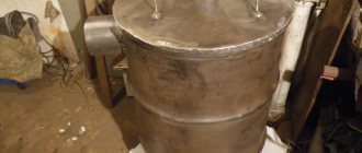
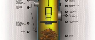
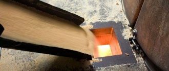
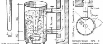
Such heat generators have a cylindrical shape, since it is hardly possible to implement the idea in a rectangular body. The firebox is filled to the top with wood, ignited from above, and then a load with a hole for air passage is lowered onto it using a telescopic pipe. As it burns, the load is lowered, which is why air is constantly supplied directly to the flame zone. The illustration below shows a diagram of a long-burning solid fuel boiler:
The air also passes through the telescopic pipe from top to bottom, driven by the natural draft of the chimney or forced by a fan. The design does not provide for a heat exchanger; the process of heating the coolant occurs directly, although the flue gases also manage to give up some of their heat. Thanks to the described combustion method, the boiler and heating system can operate with one load of wood for up to 12 hours, and coal for up to 2 days.
Features of fuel loading and operation
Assembling a heating system
From a simple boiler, where a full air supply is necessary throughout the entire volume of fuel combustion, the long-burning design, as noted earlier, is distinguished by the limitation of this supply. Moreover, the loading volume directly affects the burning time, so in our case the combustion chamber is loaded extremely tightly so that there are no gaps.
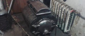
Firebox from the inside
Note! You can use not only firewood as fuel, but also sawdust, coal, peat, garbage (exclusively combustible), etc.
Fuel is loaded in this order.
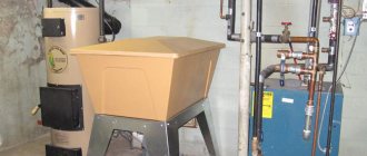
Loading the boiler
Test firing of the boiler
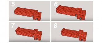
Step 1. Remove the top cover of the structure.
Step 2: Remove the air regulator.
Step 3. The boiler is loaded with fuel up to the level of the chimney pipe.
Step 4. A small amount of lighter fluid (diesel fuel, used oil, etc.) is poured over the top of the fuel.
Step 5. The air regulator is installed back, the cover is put on top.
Step 6. The air damper is opened to its maximum.
Step 7. A piece of paper is set on fire and thrown into the structure. When the fuel begins to smolder, the air damper closes.
Heating system. Harness
Heating system. Harness
The fact that permanent combustion has begun can be judged by the smoke emerging from the chimney. As the fuel burns, a pipe of smaller diameter will lower along with the air regulator - using this kind of indicator, you can determine the amount of remaining fuel.
Pyrolysis boilers
The operating principle of these heat generators is based on separate combustion in two chambers communicating with each other through a nozzle made of refractory bricks. In the primary chamber, located on top, firewood smolders with limited air supply from the fan. As a result, a process of pyrolysis occurs, otherwise known as gasification, during which a mixture of flammable gases is released. It moves to the second chamber, where it is burned when secondary air enters. The working diagram of a pyrolysis boiler operating on solid fuel is as follows:
Flue gases from the secondary furnace enter the fire tube heat exchanger in the form of vertical flues surrounded by a water jacket. There they cool, transferring heat to the water, and leave the boiler through the chimney pipe. The performance of the fan is controlled by an electronic unit - controller, based on the readings of pressure and temperature sensors.
In general, the heat generator has good efficiency indicators - about 80%, but the unit is significantly more expensive than a classic one. In addition, the boiler shows high efficiency only when operating on dry wood, although this statement is also true for other solid fuel units.
Rocket tube calculation
In addition to selecting the composition of the ceramic mixture, it is equally important to calculate the optimal dimensions of the rocket tube, because this directly affects the efficiency of the boiler. Having started the calculations, we remember that the entrance to the “J-pipe” is the bottleneck in the system. After it, all other sections should consistently increase by at least 2 cm.
Perelesnik
The only thing I did was to significantly increase the cross sections through which the hot gas passes along the walls of the heat exchanger. This slows down the flow rate.
Thus, the gas completely transfers its heat to the system, which increases the efficiency of the boiler.
To calculate the pipe dimensions, the user took as a basis the size of the pyrolysis gap for 20 kW boilers. Then, starting from this input parameter, he found the remaining dimensions of the pipe. As practice has shown, this approach has paid off.
For clarity, we present an approximate algorithm for calculating a rocket tube.
Let's take the data from the following table as a basis:
We take the first value from the table. For convenience, we convert the numbers from mm to cm. Find the area of the pipe entrance slit: 12x3 = 36. We get - 36 cm².
Further: the pipe must have a larger cross-section. Hence: if we take the internal diameter of the pipe to be 8 cm, then to find the area, we use the formula: S = πR^2, where R is the radius of the circle. We find the radius: 8/2 = 4 cm. We square the radius (to the second power), for which we multiply it by ourselves. We get: 4x4 = 16 cm. Multiply the result by the number “Pi”: 16x3.14 (rounded) = 50 cm².
If we divide 50/36, then, rounding the resulting value to 1.38, we arrive at the required ratio of the inlet area: 1.3-1.5.
Knowing the diameter of the pipe, we calculate the outer diameter of the model for casting the mold. Inner diameter – 80 mm. We add walls 10 mm thick. We get - 100 mm. We take into account that a ceramic product can shrink by 10-15%. Total: the outer diameter of the model is 110-115 mm.
The length of the vertical part of the “J-tube” is given in the American textbook on the construction of rocket furnaces, which was mentioned in the first part of the material. It is equal to 0.8-1 m. This size was obtained experimentally, maintaining it, we obtain a workable system.
The length of the horizontal section of the pipe should be less than half the length of the vertical section, i.e. less than 0.5 m. For the author of the boiler, this value is 0.3 m. You should also not make the horizontal section too short, because gases, before entering the vertical, “accelerating” part of the pipe, must warm up properly. Don't forget about thermal insulation of a short section. This will reduce heat loss and create all the conditions for afterburning gases. In order to supply secondary air to the lower part of the vertical pipe, the user added a nozzle to the design.
Pellet boilers
This group of heat generators is the most progressive of all, although the most expensive. Both the heater itself and its installation and connection will be expensive. But pellet boilers are worth the money: they are efficient (efficiency - up to 85%), fully automated and devoid of the inertia inherent in other solid fuel “brothers”. Since the fuel reserve in the bunker is enough for 3-7 days of operation, they can be safely classified as long-burning units.
Structurally, the installations are similar to gas heaters, since they are equipped with two types of burners: retort and torch. The figure shows a drawing of a long-burning solid fuel boiler using pellets with different types of burners:
The organization of heat transfer here is the same as in other heat generators - using fire tube heat exchangers. High efficiency is achieved due to something else: dry, high-quality fuel and automatically controlled combustion. But if you come across wet or loose pellets, then the efficiency of the unit will sharply decrease.
For reference. Automatic coal boilers operate on the same principle, only the burners in them are of one type - retort.
A little about DHW circuits
Due to their characteristics, any solid fuel heaters are poorly suited for direct heating of water for domestic hot water needs. Nevertheless, some manufacturers still integrate a second circuit in the form of a coil into their products. At the same time, the design of double-circuit solid fuel boilers can be different; the coil can be located inside the water jacket and heated by the coolant. In other models it is placed inside the firebox or above it.
The best option is not to place a heat exchanger inside a wood-burning heat generator, but to prepare water in an indirectly heated boiler, which will also serve as a heat accumulator. But not everyone can afford to purchase such equipment, so users are still interested in dual-circuit units, although they are unlikely to be able to provide all the needs for hot water. Below is a diagram of installing a boiler with a function of heating water for domestic hot water: