A modern chimney is not just a pipe for removing combustion products, but an engineering structure on which the efficiency of the boiler, the efficiency and safety of the entire heating system directly depend. Smoke, backdraft and, finally, fire - all this can occur as a result of an ill-considered and irresponsible attitude towards the chimney. That is why you should take seriously the selection of materials, components and installation of the chimney. The main purpose of the chimney is to remove fuel combustion products into the atmosphere. The chimney creates draft, under the influence of which air is formed in the firebox, which is necessary for the combustion of fuel, and combustion products are removed from the firebox. The chimney must create conditions for complete combustion of fuel and excellent draft. And it must also be reliable and durable, easy to install and durable. And therefore, choosing a good chimney is not as easy as it seems to us.
How to determine the temperature of the exhaust gases of the chimney
The temperature of the exhaust gases can be determined in a simple way. To do this, place a dry splinter across the view hole during combustion. After 30-40 minutes, remove the splinter and scrape off the sooty surface.
- – If the color of the splinter does not change, it means the temperature is within 150C,
- – If the splinter turns yellow (to the color of white bread crust), then the temperature reaches 200C,
- – The splinter turned brown (to the color of the crust of rye bread) – the temperature rose to 250C.
- – A blackened splinter indicates a temperature of 300C,
- – When the splinter turns into coal, the temperature reaches 400C.
When firing the furnace, the temperature of the gases must be adjusted so that at the view it is within 250. Cracks and holes in the pipe and furnace through which cold air penetrates also contribute to the cooling of the gases and the formation of condensation. When the cross-section of the pipe or chimney channel is higher than required, the flue gases rise through it slowly and the cold outside air cools them in the pipe. The surface of the chimney walls also has a great influence on the draft force: the smoother they are, the stronger the draft. Roughness in the pipe retains soot. and reduce cravings.
Principle of operation
The equipment is an exhaust or supply ventilation installation for processing air flows and supplying it to the boiler room. The device is a component of the heating system and is often connected to a central pipe. The air comes directly from the street or through the air ducts. A complex system consists of metal boxes or pipes, between which functional devices are mounted. External elements are protected from atmospheric action.
- A fan with a two-phase electric motor supplies air to the boiler room or to the common air duct.
- Filters purify the air using coarse types or the method of electrostatic sedimentation. Coarse elements are placed in front of thin filters, protect them from damage and are easily replaced.
- Heating or cooling devices change the temperature of the incoming stream. Heat pumps, electric heaters or evaporators are used.
Balancing devices, shock absorption and sound insulation in the system eliminate vibration and reduce sound during operation. The vibrations are isolated and damped by obstacles, and the fan is placed on spring supports.
Requirements for chimney material
Materials used for the production of smoke exhaust devices must meet the following requirements:
- Resistance to high temperatures;
- High resistance to corrosion;
- Resistance to aggressive chemicals and environments.
All these requirements for a chimney for a gas boiler have a real basis. Thus, the requirement for chemical inertness is due to the fact that in the chimney pipe during operation of a gas boiler there is a certain amount of condensate containing sulfuric acid. To ensure that such an environment does not damage the structure, it must be protected from corrosion and chemical attack. The intensity of condensation can be reduced by insulating the chimney.
Types of boilers and smoke exhaust ducts
Gas boiler with coaxial chimney
The industry produces various models of gas heating boilers, but all types are built in two possible designs: with an open or closed chamber for gas combustion.
It is better to decide which boiler to purchase at the stage of designing a house. The chosen scheme determines how and where to build the boiler room, as well as how combustion products will be removed.
The project must be agreed upon with the gas supply organization - if construction technology is violated or unacceptable materials are used, gas equipment will not be put into operation, and alteration of the gas exhaust system may require significant financial costs.
Open chamber boilers
By design, devices with an open chamber are simpler than devices with a closed type.
Oxygen for fuel combustion is supplied from the surrounding space. This feature imposes additional requirements on the organization of room ventilation.
Equipment installation is carried out only in a separate room. To ensure operation, two channels are built to supply air and remove products from the burnt gas.
Among the advantages is the relative simplicity of the design without additional fans, and therefore without “extra” mechanical parts that are most susceptible to wear. The disadvantages should be considered lower efficiency and the need to build a vertical chimney at a level above the roof ridge.
Features of equipment with a closed chamber
In a coaxial chimney, air is sucked in through one pipe and comes out through another - internal
Air is forced into gas boilers with a closed chamber. The chamber does not communicate with the room air, and the exhaust gases are removed by a supercharger.
Boilers with a closed chamber are economical, do not require the installation of vertical channels, and one coaxial pipe is used. Combustion products are removed through the internal insert, and external clean air enters through the cavity between the walls of the pipes.
To remove gases, there is no need to build vertical structures, which reduces the cost of the estimate. On the other hand, this type of boilers and pipes requires more frequent maintenance. Turbines periodically fail, which entails additional operating costs.
Gas boilers
Most often, gas boilers are used to heat private houses. Their popularity is due to the affordable price of fuel and its high efficiency. Leading companies from Russia and Europe produce high-performance boilers. The temperature in the chimney of gas boilers with high efficiency usually does not exceed 80-100 degrees
, and in most cases even lower.
The combustion process of natural gas in its most simplified form is described by the formula CH4 + 2O2 = CO2 + 2H2O (complete combustion of methane). That is, from two molecules of oxygen and one molecule of methane, one molecule of carbon dioxide and two molecules of water are formed. When 1 cubic meter of gas is burned, an average of 2 liters of liquid is released. This water reacts with the oxides contained in the smoke and forms a set of acids. Since the temperature of the exhaust gases is low (all thermal energy is spent on heating water in the heating system), the dew point is located inside the chimney pipe. In this regard, condensation settles on the walls.
For gas boilers, pipes with high corrosion resistance should be selected. For example, traditional brick structures will not last long in such conditions. Moisture will penetrate microcracks and seams between bricks, which will ultimately lead to destruction of the material, and temperature changes will only accelerate this process. In addition, the condensate contains nitric, sulfuric and other acids, and therefore is highly aggressive.
Since the temperature in the chimney of a gas boiler affects the formation of condensation and service life, it is necessary to pay close attention to the inner surface of the passages. Most people install chimneys from stainless steel pipes. In general, the solution is not bad, but their service life is short, since aggressive acids can destroy even alloy steel. A ceramic pipe may be a more reliable option. It has excellent corrosion resistance, but is much more expensive. Among modern materials, plastic chimneys are gaining popularity, which are also not afraid of condensation. But before installing plastic pipes, make sure that the boiler manufacturer does not exclude this possibility. They are designed only for low exhaust gas temperatures.
If the gas boiler is planned to be connected to an existing brick system, then it is necessary to sleeve it. For lining you need to use moisture-resistant material. This can be a stainless or ceramic pipe. A polymer sleeve would be an excellent option, as it is suitable for structures of any complexity and size.
Advantages and disadvantages of coaxial chimneys
Such systems for supplying air and removing combustion products have now gained wide popularity.
This is easily explained by the many advantages of such a scheme: First of all, the advantage is that the air necessary for the combustion of “blue fuel” is taken not from the room, but from the street. This circumstance greatly simplifies the organization of general ventilation - no calculations are required for additional inflow, there is no need to resort to frequent ventilation or organize other ways of air supply from the street
This is especially important for those cases when the boiler is installed in the “living area” of a house or apartment, for example, in the kitchen. In frosty weather there will be no unnecessary influx of cold into the premises. In principle, combustion products cannot enter the room - they are immediately discharged from the closed chamber to the street. The air taken from the street receives very noticeable heating from the internal pipe, through which waste products flow in a counter flow
And this is important for uniform and complete combustion of gas, for maximum boiler efficiency. In addition, complete combustion of gas ensures minimal emissions of substances that can cause air pollution. On the contrary, combustion products are effectively cooled, which significantly increases the fire safety of the system. The likelihood of ignition of soot particles, which can accumulate in the pipe over time, is sharply reduced. And at the outlet the gases no longer have a dangerous temperature. The outer surface of the coaxial pipe does not heat up to too high temperatures. And this is a big “plus” in the sense that the requirements for organizing safe passage through walls (floors, roofs) are significantly reduced. No other type of chimney, including sandwich pipes, allows such “liberty”.
Even through a wooden wall, you can lay a coaxial chimney without cutting out a huge window for a fireproof penetration.
- Installation of a coaxial combustion product exhaust system will not involve large-scale construction and installation work, as usually happens when installing “classic” vertical chimneys.
- The installation itself is quite simple and intuitive. Any kit is always accompanied by detailed instructions. So in many cases it is quite possible to carry out the installation work yourself.
- There is a wide range of coaxial chimney kits on sale, and therefore it is possible to select the desired system for a boiler of a certain model. As a rule, it is purchased immediately along with the heating equipment. And for any system, the assortment includes the necessary additional parts - tees, 90 or 45 degree bends, condensate collectors, inspection chambers, cuffs, clamps, fasteners, etc. That is, there are no problems with acquisition.
The main disadvantage of coaxial chimneys is the abundant formation of condensation, which is inevitable at the border of distinctly hot and cold gas flows. And as a result, ice freezes at the tip in severe frosts. And this, in turn, is fraught with failure not only of the combustion product removal system itself, but even of the heating unit.
In severe frosts, despite the very hot exhaust, ice build-up may form on the pipe of the coaxial chimney. This phenomenon must be combated so as not to “ruin” the entire system.
This drawback is often attributed to the fact that coaxial chimneys were originally developed for European countries with much more benign climatic conditions than in Russia. In an effort to increase the efficiency of boilers, designers tried to reduce to a minimum the possible diameter of the internal pipe for gas removal, which led to a shift in the dew point inside the air duct and heavy freezing of the condensate that fell.
Additional insulation of the outer section of the outer pipe of a coaxial chimney is a simple and effective means of combating icing.
The second, but very conditional, disadvantage is the high cost of high-quality coaxial chimneys. But there is something to argue with here. Firstly, the price still doesn’t look scary compared to the overall costs of the heating system. And secondly, if you add considerable savings on construction and installation work, then it becomes ridiculous to talk about cost in general. And this is without taking into account the other advantages of the coaxial system.
Normal temperature of gases leaving the furnace
In order for the water present in hot gases to evaporate better, the temperature of the latter must be increased. On well-heated pipe walls, settled drops of moisture quickly evaporate.
The normal temperature of gases leaving the furnace before exiting into the pipe is 12O...14O°C, when leaving the pipe into the atmosphere - not lower than 100°C.
If the flue gases, when exiting into the chimney, that is, at the view, reach a temperature of about 250 ° C, then condensation does not form, draft improves, the stoves heat up faster, while consuming less fuel.
The temperature of the exhaust gases can be determined using a dry splinter, which is placed across the view hole during combustion. If after 30...40 minutes you remove the splinter and scrape off the sooty surface from it with a knife, you can set the temperature of the gases. The color of the splinter does not change at temperatures up to 150°C. If the torch turns yellow (to the color of a white bread crust), it means the temperature has reached 200°C;
Thus, when firing the furnace, the temperature of the gases must be adjusted so that at the viewer it is within 250°C.
SEARCH
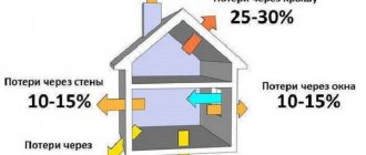
Heat losses to the atmosphere by the furnace masonry and returbents depend on the surface of the furnace, the thickness and material of the masonry and roof.
They make up 6-10%. Heat loss from the walls of the combustion chamber is estimated at 2-6%, and in the convection chamber within 3-4%. Heat losses from flue gases depend on the excess air coefficient and the temperature of the gases leaving the chimney. They can be identified from Fig. 177 (a and b), taking into account that the temperature of the flue gases during natural draft should not be lower than 250 ° C and 100-150 ° C higher than the temperature of the raw materials entering the furnace. By using the heat of exhaust flue gases to heat the air using artificial draft, it is possible to significantly reduce heat loss and have a tubular furnace with an efficiency of 0.83-0.88. [p.284] Temperature of the flue gases at the pass, i.e., the temperature of the flue gases entering the convection chamber. Usually this temperature is in the range of 700-900 ° C, although it can be lower. It is not recommended to increase the temperature of gases at the pass excessively, as this can cause coking and burnout of the radiant pipes. [p.104] And only by shielding the combustion chamber and increasing its volume were normal conditions created for the operation of the coil. Radiant-type tubular furnaces were created. In early designs of such furnaces, the ceiling screen pipes were protected from severe flame exposure by cuffs made of fire-resistant material. Corrugated cast iron cuffs on convection pipes increased the heating surface in the convection chamber of the furnace. As a result of shielding the furnace ceiling, heat transfer by radiation increased, the temperature of the flue gases above the pass decreased, and the need for protective cuffs and flue gas recirculation was eliminated. For maximum heat utilization [p.273]
Flue gas temperature after boiler - 210 210 — [p.219]
Technological design standards provide for a reduction in the temperature of flue gases before entering the chimney at natural draft to 250 °C. If you have special smoke exhausters, the temperature can be reduced to 180-200 °C. The heat of flue gases having a temperature of 200-450 ° C (average figure) can be used to heat air, water, oil in the installation and to produce water steam. Below are data on the thermal resources of flue gases at an ELOU-AVT installation with secondary distillation of gasoline with a capacity of 3 million tons/year of sulfur oil [p.211]
Average flue gas temperature of 293 305 310 - [p.219]
The temperature regime of raw material heat exchangers is also limited. The maximum permissible temperature at a regeneration pressure of 3.0-4.0 MPa should not exceed 425 ° C, and therefore the temperature of the flue gases leaving the reactors before entering the raw heat exchanger should be reduced by mixing with a cold coolant. [p.129]
Thermal intensity of pipes, kcal/(m2-h) radiant convection Flue gas temperature, [p.121]
Surface of heaters, Air heating temperature in heaters, °С Temperature of flue gases, °С [p.186]
Typically, the temperature of the flue gases at the pass is automatically regulated with correction based on the temperature of the product at the outlet of the furnace. To monitor and regulate tube furnaces, the following elements are provided in their piping. [p.48]
Liquid fuel consumption, kg/h Flue gas temperature at the furnace outlet, °C. . . . Flue gas volume at gas outlet temperature from 4000 3130 2200 [p.211]
Flue gas temperature in front of the boilers, °C 375 400 410 — [p.219]
In drying installations, the material being processed is not in close proximity to the furnace, as is the case in furnaces for various types of cooking, distillation and similar boilers. Therefore, the temperature in the combustion chamber of the drying installation can be significantly higher than the temperature in the furnaces, in in which the devices that consume heat are located. However, in this case, the temperature is determined by the properties of the material being dried and the requirements dictated by the quality of the product. Some types of raw materials do not tolerate high temperatures, so it is necessary to reduce the temperature of the flue gases to the temperature [p.252]
Based on the amount of heat given off by a given amount of flue gases in the radiation system, the temperature of the flue gases entering the convective system is determined. [p.269]
During operation of the regenerator, the flue gas temperature may exceed normal due to the combustion of carbon monoxide. If this phenomenon is detected in a timely manner, it is necessary to redistribute the air across sections, reducing the supply to those sections where there is excess oxygen in the flue gases leaving the section, and increasing its supply to sections where there is not enough oxygen. In the event of a sharp increase in the temperature of the exhaust gases, the air supply to individual or all sections is temporarily stopped. [p.153]
Primary reforming of natural gas with steam is carried out in vertically located pipes heated by flue gases, the lower ends of which are introduced directly into the secondary methane reforming reactor. A portion of the flue gases is fed through a perforated plate into the secondary reforming catalyst bed, which produces nitrogen-enriched gas. Flue gas temperature - 815° C [p.97]
Fire-type stoves have been replaced by convection stoves, in which the pipe coil is separated from the combustion chamber by a pass wall. During the operation of such furnaces, significant disadvantages were identified: high temperature of the flue gases above the pass wall, melting and deformation of the brickwork, burnout of the pipes of the upper rows of the coil. To reduce the temperature in the combustion chamber, flue gas recirculation was used and fuel was burned with an increased excess air ratio. However, increased air flow reduced the efficiency of the furnaces and did not reduce pipe burnout. [p.273]
Temperature at the superheater. In some cases, a coil is installed in the convection section of the furnace to superheat water vapor supplied to distillation columns for stripping low-boiling fractions. The superheater is placed where the temperature of the flue gases is 450-550 ° C, i.e. in the middle or lower section of the convection chamber. The temperature of superheated steam is 350-400° C. [p.282]
The temperature of the flue gases above the pass wall is especially important. The high temperature of gases at the pass corresponds to high thermal stress on the surface of the radiant tubes, the temperature of their walls and a high probability of coke formation. Being deposited on the inner surface of the pipes, coke impedes heat transfer, which leads to a further increase in the temperature of the walls and to their burnout. [p.283]
Increasing the speed of movement of the heated raw material in the furnace pipes increases the efficiency of heat removal, reduces the temperature of the pipe walls and, thus, makes it possible to work with higher thermal intensity of the radiant pipes and the temperature of the flue gases at the pass. [p.283]
A typical ELOU-AVT (A-12/9) installation with a capacity of 3 million tons/year with secondary distillation of gasoline has five furnaces with a total thermal capacity of 81 Gkcal/h. In all furnaces, 11,130 kg of fuel are burned in 1 hour. The temperature of the flue gases at the exit from the convection chambers of the furnaces is 375–410 °C. To use the thermal energy of flue gases before entering them into the chimney, remote waste heat boilers of the KU-40 type are installed in the furnaces. [p.219]
The lower the temperature of the flue gases leaving the convection chamber, the more heat is absorbed by the heated oil product. Typically, the temperature of the flue gases at the exit from the convection chamber is taken to be 100-150 ° C higher than the temperature of the raw materials entering the furnace. But since the temperature of the raw materials entering the furnace can be quite high, approximately 160-200 ° C, and for some processes reaches 250-300 ° C, then to utilize the heat of the flue gases, an air heater (recuperator) is installed, in which the air going into the furnace is heated ovens. If there is an air heater and a smoke exhauster, it is possible to cool the flue gases before releasing them into the chimney to a temperature of 150° C. With natural draft, this temperature is at least 250° C. [p.90]
Convection pipes receive heat through convection of flue gases, radiation from masonry walls and radiation of triatomic gases. As noted at the beginning of the chapter, heat transfer in a convection chamber depends on the velocity and temperature of the flue gases, as well as the temperature of the feedstock, the diameter of the pipes and their arrangement. The speed of flue gases in a convection shaft usually varies between 3-4 m/sec, and in a chimney 4-6 m/sec. [p.107]
Solution. Let us determine the efficiency of the furnace if the temperature of the flue gases at the exit from the convection chamber [p.113]
The temperature of the flue gases at the outlet of the furnace is 500 C. The heat of the flue gases is utilized in a tubular three-pass (via air) air heater with a heating surface of 875 m2. After the air heater, flue gases at 250 C are removed into the atmosphere through a chimney without the use of forced drafts. [p.107]
Let us set the temperature of the flue gases after the heating section of the radiation chamber to g, c = 850° C, and after the reaction section ip. c = 750° C. Heat content of flue gases but fig. 6. 1 at a = 1.1 [p.120]
A distinctive feature of waste heat boilers, as equipment for generating steam, is the need to ensure the passage of a large amount of heating flue gases per unit of generated water steam (E1/d.g/C). This ratio is a direct function of the initial temperature of the flue gases at the entrance to the apparatus and their flow rate. Due to the relatively low temperature of the flue gases for generating steam, their specific consumption in waste heat boilers is much higher (8-10 times) than in conventional combustion boilers. The increased specific consumption of heating gases per unit of generated steam predetermines the design features of waste heat boilers. They have large dimensions and high metal consumption. To overcome additional gas-dynamic resistance and create the required vacuum in the furnace firebox (draft), 10-15% of the equivalent electrical power of the waste heat boiler is spent. [p.76]
Having filled the hopper with dried catalyst, open the valve under the hopper and pour the catalyst into the calcination column. The volume of the hopper corresponds to the useful volume of the calcination column, i.e. one load. Having filled the column with a catalyst, the furnace is ignited under pressure (using liquid fuel), directing the flue gases into the atmosphere. Then, having adjusted the combustion in the furnace, the flue gases are introduced into the casing of the calcination column. After heating the casing and making sure that the fuel is burning normally, the flue gases are directed to the bottom of the calcination column in the minimum amount necessary only to overcome the resistance of the catalyst layer. Then they begin to slowly raise the temperature of the flue gases at the exit from the furnace and warm up the catalyst. Warming up of the system continues for approximately 10-12 hours, during which time such an amount of flue gases is introduced so that there is no carryover of the catalyst from above. Reaching a temperature at the bottom of the column of 600-650° C is considered the beginning of catalyst calcination. The duration of calcination at this temperature is 10 hours. [p.68]
Then they gradually lower the temperature of the flue gases at the exit from the furnace and at 250-300 ° C they stop supplying fuel, but [p.68]
The temperature of the gases at the pass, the thermal tension of the heating surface of the radiant tubes and the direct efficiency coefficient of the furnace are mutually related. The higher the direct return coefficient, the lower, other things being equal, the temperature of the flue gases at the point of maturity and the lower the thermal tension of the heating surface of the radiant pipes and vice versa. [p.105]
Tubular coil reactors. A tubular coil reactor with a vertical arrangement of pipes was developed for the production of bitumen in a continuous manner at domestic refineries [2, 55, 190]. Temperature conditions of reactors. (Kremenchug and Novogorkovsky refineries) is maintained by the heat of flue gases coming from the prechamber furnace. However, this solution does not take into account the specifics of the exothermic oxidation process. Indeed, to accelerate the heating of the reaction mixture in the first reactor pipes along the flow, it is necessary to increase the temperature of the flue gases, but as a result, the oxidized material in subsequent pipes is overheated, where the oxidation reaction and heat release occur at high rates. Thus, it is necessary to maintain some intermediate temperature of the flue gases, neo[tpmal y, both to heat the reaction mixture to the reaction temperature, and to subsequently maintain the temperature at the desired level. For the installations of the Angarsk, Kirishi, Polotsk, Novoyaroslavl and Syzran refineries, a more successful solution has been found: the raw materials are preheated in a tube furnace, and excess reaction heat, if necessary, is removed by blowing air through the reactor pipes placed in a common casing (according to the design of the Omsk branch of VNIPIneft, each reactor pipe placed in a separate casing). [p.130]
If the temperature of the flue gases at the exit from the common collecting manifolds of the regenerator exceeds 650°, this indicates the beginning of carbon monoxide afterburning. To stop it, it is necessary to sharply reduce the air supply to the upper part of the regenerator. [p.145]
In order to reduce the temperature of the flue gases above the pass wall, in old-style radipant-convection furnaces, especially thermal cracking furnaces, flue gas recirculation is used. Cooler flue gases from the furnace hog are returned to the combustion chamber, which leads to heat redistribution between the chambers. In the convection chamber, the thermal tension of the upper pipes is reduced, but due to the increase in the volume of flue gases, their speed increases, and heat transfer throughout the convection chamber improves. The recirculation coefficient in tube furnaces ranges from 1 to 3. [p.90]
The imperfect design of the burners of furnaces and boilers for burning fuel and the insufficient sealing of the furnaces do not yet allow operation with small excess air. Therefore, it is believed that the temperature of the air heater tubes should be higher than the dew point temperature of aggressive flue gases, i.e. not lower than 130 °C. For this purpose, preliminary or intermediate heating of cold air or special heating surface layout schemes are used. There are devices that are structurally designed in such a way that the heat exchange surface on the flue gas side is much larger than on the atmospheric air side, so air heater sections are assembled from pipes with different finning coefficients, increasing towards the cold end (to the point of entry of cold air), and thus the temperature the pipe walls approach the temperature of the flue gases. Bashorgener-Goneft air heaters are constructed using this principle from cast-iron finned and ribbed-toothed pipes with good performance indicators. [p.80]
The catalyst is heated and calcined by direct contact with flue gases coming from the furnace in which gaseous or liquid fuel is burned. The temperature of the flue gases is automatically maintained at the level of 630-650 ° C, while the temperature in the calcination zone is 600-630 ° C. The calcined catalyst enters the cooling chon through the iridescent tubes of the lower grille-gate, where it moves between rows of air-cooled pipes and It cools itself to the desired temperature. A movable metal cup is placed at the end of the refining tube, the position of which regulates the height of the catalyst layer on the conveyor located below and, consequently, the speed of product unloading. A conveyor belt feeds the unloaded catalyst into a screen for screening out fines. Next, it is poured into metal barrels and delivered to the finished product warehouse. [p.70]
The higher the temperature of the heated raw material in the radiant tubes and the greater its tendency to coke formation, the lower the thermal intensity should be, and therefore, the lower the temperature of the flue gases above the pass. For this furnace, an increase in the surface of the radiant tubes leads to a decrease in the temperature of the flue gases above the pass and the heat intensity of the radiant tubes. Contamination of the inner surface of the pipes with coke or other deposits can lead to an increase in the temperature of the flue gases above the pass and to burnout of the first rows of pipes in the convection chamber of the furnace. The temperature over the pass is carefully controlled and usually does not exceed 850-900° C. [p.283]
The temperature of the flue gases above the pass wall is usually maintained at 700-850 ° C, i.e., high enough to transfer part of the heat by radiation to the upper rows of pipes of the convection chamber. But the main amount of heat in the convection chamber is transferred due to forced convection of flue gases (created by a chimney or smoke exhauster). [p.89]
The fraction of distillate at the furnace outlet is e = 0.4, the density of distillate vapor = 0.86. residue density = 0.910. The diameter of the pipes in the radiation chamber is 152 X 6 mm, in the convection chamber 127 X 6 mm, the useful length of the pipes is 11.5 m, the number of pipes is 90 and 120 pieces, respectively. The fuel composition and theoretical air flow are the same as in examples 6. 1 and 6. 2, the heat content of flue gases with excess air a = 1.4 can be found from Fig. 6. 1. Flue gas temperature at the pass [p.109]
The total duration of hydrothermal treatment including heating is approximately one day. After the pressure in the apparatus begins to drop, the temperature of the flue gases at the outlet of the furnace is gradually reduced and, finally, the nozzle is extinguished. The apparatus is cooled with cold air from the firebox through the casing. The dried balls are unloaded and sent to the hopper of the calcination column. [p.127]
Suction pyrometers. In the practice of measuring high flue gas temperatures, suction pyrometers are used. The main elements of suction pyrometers are a thermocouple placed in a cooled housing, a screen system and a device for suctioning gases. Thermal electrodes are insulated from one another and from the protective cover by rigid elements (straw tubes, single- and double-channel beads) made of quartz (up to 1100°C), porcelain (up to 1200°C), and porcelain with a high alumina content (up to 1350°C ) ceramic materials and glass enamels applied by broaching methods. [p.139]
When the niroscoils become coked, there is a gradual increase in the temperature of the pipe wall, the pressure drop increases, and white spots may be observed in places where the pipes are overheated. The formation of coke deposits in the pyro-coils is also judged by the increase in the temperature of the flue gases at the furnace pass. Coking of the IIA is characterized by an increase in the hydraulic resistance of the system with an increase in the temperature of the pyrolysis products after the IIA. An increase in hydraulic resistance in pyro-coils and ZIA is accompanied by an increase in pressure in the furnace unit and, as a result, the contact time increases and the yield of lower olefins decreases. [p.198]
chem21.info
Let's look at examples of condensation occurring in a chimney.
Smoldering mode.
“Condensaaaaat! “
This is exactly how you want to scream when you see people connecting metal stoves with smoldering mode to brick pipes.
All arguments usually cannot overcome the issue of price.
The user, having bought an inexpensive and quite nice stove like a “potbelly stove” in a store, connects it to a brick pipe left after dismantling a poorly functioning old brick stove.
As a result, this design condenses and stinks throughout the whole house.
The cause of condensation, in this case, is the smoldering mode.
Read more about smoldering mode here.
The final result, most often, is the destruction of the chimney.
Low temperature of gases leaving the furnace into the chimney.
An illiterate stove maker made too many channels or caps in a brick stove.
Result: Passing through many channels, the flue gases are too cooled, and their flow rate is also significantly reduced.
Condensation falling in the chimney destroys the brick.
One day, summer residents approached me with a request to relay the pipe.
The owner of the house assured that the brick in the chimney was falling apart because the stove maker soaked the brick.
I tried to explain:
- About condensation.
- About the fact that 7 channels are too many for her stove.
- About flow speed, gas temperature, etc.
As a result, her husband said: “Bullshit! The stove is good, very warm. And the black water flowing out of the valve is from the rain.”
I don’t know further about the history of that stove, because... there was nothing more to talk about.
This furnace was condensing due to the asbestos-cement pipe above it.
The chimney cross-section is too large.
Fortunately, asbestos-cement pipes are being installed less and less on new stoves.
The cross-section of asbestos-cement pipes is usually much larger than necessary for the furnaces to which they are connected.
A large chimney cross-section inevitably leads to condensation.
The asbestos-cement pipe itself is as sensitive to condensation as a light bulb, but the condensate will flow through it into the furnace.
Often, on old stoves, condensation even begins to flow out of the stove’s cleaning doors and seep through the seams.
Poor quality firewood can also lead to condensation in the chimney.
Read more about the quality of firewood here.
Where to start the installation?
- First you need to mark the installation location on the wall or on the floor, depending on the type of boiler.
- Check whether there are enough parts and other auxiliary elements. In general, we mentally install the boiler at its future place of operation.
- View installation instructions.
IMPORTANT! Alone, you can only install a small-sized or floor-standing boiler (and even then not always). In most cases, you will need the help of one or two people.
Premises requirements
- The size of the installation room depends on the power of the boiler. The minimum area is 4 square meters, and the ceiling height is 2-2.5 meters.
- The doorway is at least 80 centimeters wide.
- Windows are a must. The minimum requirement for a 4 square room is a small window measuring 0.15 square meters.
- For every kilowatt of device power there should be 8 cubic centimeters of ventilation.
- Gas pipes must be metal, no other material is allowed.
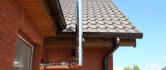
- The diameter of the chimney should depend on the power. The minimum diameter is 13 cm, and it should not taper towards the top and should protrude above the roof surface by at least half a meter.
- There should be gas sensors in the room, and a gas stop valve on the boiler itself.
- The boiler must be equipped with a fuel flow sensor.
- In an apartment building, you can install the boiler everywhere except the basement, and in a single-apartment building it is recommended to install it in the basement.
- The boiler power supply (for autonomous boilers) and the electricity supply system must have thermal insulation and electrical insulation screens.
How to install equipment correctly
Strictly follow all the rules and regulations of SNiP 42-01-2002 “Gas distribution systems”, without deviating from them.
Any attempt to improvise or change classical technology may be noticed by inspectors.
And if this causes an accident or losses to other residents of the house, the owner faces administrative, and, in some cases, criminal penalties.
- If the boiler is wall-mounted, the floor under it must be perfectly level, since the pump pumping water can cause vibration and displacement of the boiler. If the vibration is strong, the gas pipes or water supply system may become disconnected from the boiler, leading to a gas leak or flood.
- If it is possible to make a stand for the boiler, this will secure the structure and increase the adhesion strength to the floor.
- If you install the boiler near a stove, boiler or other heating elements, then the total power of the thermal field between them will be higher than what the sensors show, since they measure this only inside the system itself. This rule is not specified in SNiP, but is often the cause of premature wear of the mechanism or failure.
Documentation
Required documents:
- A summary of the fuel consumption of a specific device. This can be done both by the workers who install the boiler and by the owner-installer himself. The technical data sheet of the device must indicate data on the consumption of electricity, gas and water. Within 14 days, a gas service employee must issue preliminary consent to install the unit.
- Installation project, which indicates all installation points and steps, communication connection diagram and chimney outlet.
- Technical specification, which specifies data on installation and communication to the boiler.
- Certificate of the device, reviewed and certified by gas workers. Certificate of standardization of the boiler.
Once the project has been approved, installation can begin. Professionals typically keep an installation protocol that outlines basic steps to protect themselves in the event of equipment failure or an accident that results in damages.
The protocol is signed by the customer (boiler owner). If you are installing it yourself, the protocol should indicate the main steps specified in the instructions for the boiler. If an accident occurs during installation or the boiler does not function properly, the protocol will serve as legal protection.
ATTENTION! In the case when the installation is carried out by specialists, and the protocol is signed by the customer, it has legal force, and if the installation is performed by the customer himself, the protocol is a regular description of the actions.
Types of systems
The design of sauna stoves includes 2 types of chimneys:
- Indigenous. They are organized next to the stove, using a special pipe for connection, through which the smoke goes into the main channel. One chimney can be used for 2-3 stoves. The main thing is that its internal diameter has the appropriate parameters, and the pipes from each heating device are located at different heights;
- Systems with a mounted pipe are mounted directly on the stove pipe and discharged through the roof. This chimney option is the most common for sauna stoves.
Classification of chimneys according to installation location includes 2 types:
- External. Their main part is located on the street and fixed to the wall using a bracket. They are not particularly recommended for baths, as they quickly cool down, losing precious heat.
- Internal. These are vertical structures with good traction, located inside the building.
Depending on the material used, chimneys are:
- Brick. A traditional look, characterized by labor-intensive masonry and high requirements for compliance with all parameters. They have a lot of advantages: durability, fire safety, strength, good thermal insulation and heat accumulation. Disadvantages include the roughness and angularity of the inner surface on which soot deposits accumulate;
- A metal chimney is faster to install and costs less. It has a perfectly smooth surface, but weaker heat-retaining characteristics;
- A combined version, including 2 parts: the lower one is made of brick, the upper one is made of a modern sandwich pipe. Allows you to organize neat, small passages that are easier to cover with heat-resistant material.
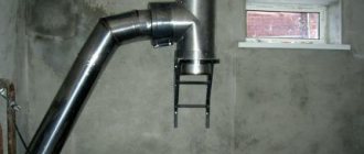
Chimney device for a turbo boiler
The coaxial flue duct is a double-walled “pipe-in-pipe” structure that simultaneously performs 2 functions: removing smoke to the outside and taking in combustion air from the street. Hot gases move along the internal channel, the air flow goes towards the outer channel (between two walls).
Important point. The forced movement of combustion products and air is provided by the gas boiler fan; natural draft does not work here. At the same time, the coaxial chimney cannot be connected to turbocharged units using other types of fuel - wood, pellet or diesel.
The diagram shows a vertical version of the chimney, but more often it is installed horizontally
The 2 in 1 chimney system “air/combustion products” provides the following advantages:
- Hot gases give off some of the heat to the air flow, the combustion process improves, and the efficiency of the heat generator increases.
- The coaxial pipe is led out horizontally, using the shortest route through a hole in the outer wall. In some cases, vertical installation is possible.
- Thanks to the double-walled design of the flue, the turbo boiler or column can be installed in almost any room without a traditional smoke duct - the kitchen of a country cottage, garage, basement and even in a bathhouse. The room must meet the requirements for gas boiler rooms.
- The owner does not need to worry about the additional flow of air needed for combustion. Although general ventilation will still have to be done.
The disadvantage of the chimney system is the freezing of the tip in severe frost. The sucked air comes into contact with the hot wall of the inner pipe and releases condensation, forming an icicle. The problem is solved by installing a special stainless steel extension cord.
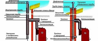
Main elements of a coaxial chimney:
- straight section with a head at the end;
- the same double-walled bend at 90° or 45°;
- adapter – adapter for the coaxial output of the boiler;
- connecting clamps, flanges;
- elastic cuffs, aprons;
- inspection section with condensate drain (for vertical installation);
- fastener
Installation kit for the STOUT coaxial system for horizontal installation. The adapter is suitable for gas heat generators Bosch, Buderus.
We will tell you how to install coaxial elements correctly below. But first we suggest you study...
Liquid fuel boilers
When solid and, especially, liquid fuels are burned, a larger number of different oxides are formed. This is due to the impurities contained in the fuel, in particular sulfur. When water combines with sulfur oxides, sulfuric acid is formed. Dew from sulfuric acid vapor falls earlier than from water vapor. This leads to the fact that if the gas temperature in the chimney is not high enough, the pipe is subjected to strong aggressive influence. This factor must be taken into account when choosing a material.
If you look at it, both high and low temperatures inside the chimney affect its service life. To ensure that replacement of the chimney of a gas boiler or fireplace is not required soon after installation, you need to choose the right material. It is necessary to take into account the peculiarities of the processes that occur inside the system, the effect of temperatures, the possible formation of condensation and other factors. If you do not have the necessary knowledge, it is better to consult a specialist. Attempts to save money by purchasing the cheapest material usually end in rapid failure of the chimney. Remember that the system must work properly. Select the chimney according to the type of equipment used.
Stages of preparation for boiler installation
Before the home owner begins installing the heating system, you will need to collect some documents:
- agreement on supplying the house with gas;
- technical specifications and installation diagram of the gas system, approved by the relevant authorities;
- written permission from the gas inspector to install the equipment.
Use of wood based on its heat capacity
When choosing a type of firewood, it is worth considering the ratio of cost and heat capacity of a particular wood. As practice shows, the best option can be considered birch firewood, which has the best balance of these indicators. If you purchase more expensive firewood, the costs will be less effective.
To heat a house with a solid fuel boiler, it is not recommended to use types of wood such as spruce, pine or fir. The fact is that in this case, the combustion temperature of the wood in the boiler will not be high enough, and a lot of soot will accumulate on the chimneys.
Firewood made from alder, aspen, linden and poplar also has low thermal efficiency due to its porous structure. In addition, sometimes during the burning process alder and some other types of firewood shoot out coals. In the case of an open furnace, such micro-explosions can lead to fires.
It is worth noting that no matter what the wood is, if it is damp, it burns worse than dry wood and does not burn completely, leaving a lot of ash.
Features of operation
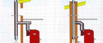
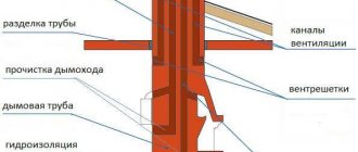
Installation of a gas boiler chimney and its connection is such a responsible undertaking that it is best to entrust it to a gas specialist. But if you decide to do it yourself, you need to strictly fulfill the following requirements:
- Connecting more than one gas boiler to the chimney by combining pipes is unacceptable. With this design, combustion products will enter the house.
- It is prohibited to combine galvanized elements with brick, asbestos and aluminum.
- Work can only begin after careful calculations of the chimney cross-section in accordance with the parameters of the purchased gas boiler.
- The length of the chimney must be at least 5 meters from the lower level of the firebox to the upper end.
When installing any type of chimney other than coaxial, it is important to position it at the correct height
- When installing a chimney on a building with a flat roof, the height of the pipe above the roof must be more than 1.5 meters.
- The head of the pipe, the axis of which is located at a distance of 1 to 3 meters from the ridge, must be no lower than its level.
- If the distance from the pipe to the ridge is less than 0.5 meters, the elevation of the pipe above the junction line of the slopes must be at least 0.5 meters.
- If the length of the part of the pipe above the roof is more than two meters, it must be strengthened with additional guy wires in an amount of at least three pieces.
- A deflector must be installed on the head of the pipe.
Installing a deflector increases traction by 20–25%
Checking the draft in the chimney of a gas boiler
The reason for checking is obvious indicators of improper combustion of the boiler, which can be recognized by the following signs:
- The smell of gas and a feeling of smoke in the room.
- Changing the color of the burner flame towards red. This is a clear sign of incomplete combustion of fuel.
If these circumstances exist, you must immediately turn off the gas supply and ventilate the premises. After this, check the draft in the pipe and determine the reason for its insufficiency:
- Check the position of the draft control devices: gate or rotary valve. They must be in the open or intermediate position.
- Use an anemometer to measure the speed of air movement in the area of the firebox window. Although it is unlikely that anyone will buy an expensive device, since you can use traditional methods.
- Bring a strip of newspaper or toilet paper to the opening. With normal draft, it will actively bend towards the boiler. The test can also be carried out with the flame of a candle, lighter or match.
The easiest way to check the presence of draft is by holding a match to the firebox - the flame should deviate towards the chimney
The reasons for the drop in traction may be:
- Insufficient pipe height. Under certain weather conditions, traction may deteriorate or disappear altogether.
- Contamination of the chimney with soot, as a result of which the effective cross-section of the channel has critically changed.
- Lack of deflector at the upper end of the pipe. With a certain direction and strength of wind, air currents may arise that prevent combustion products from leaving the chimney until reverse draft is formed.
It is necessary to reliably establish the cause of the drop in traction and eliminate it. The house must have an alternative source of heat . Then measures to eliminate the causes of the drop in traction can be carried out in a calm environment and in comfortable conditions.
Video: checking the draft in the chimney of a gas boiler
https://youtube.com/watch?v=44GtClQZ8s8
Solid fuel boilers
The choice of chimney for a solid fuel boiler, stove or fireplace is significantly different. The main criterion is that the material must be resistant to high temperatures. The fact is that the principle of their operation differs from gas boilers. The process of burning wood, coal or briquettes is accompanied by high temperature. As a consequence, the temperature of the combustion products exiting is also high. Despite the variety of modern materials, brick remains the best option. Popular metal pipes, including stainless steel ones, quickly burn out, so their service life is short. Plastic pipes are categorically not suitable for solid fuel boilers, since they cannot withstand high temperatures. Cheap asbestos pipes can be used, but they are designed for gas temperatures of no more than 300 degrees.
Installation recommendations
When installing a traditional gas duct, it is necessary to comply with fire safety requirements. These include the installation of a steel case in the case of a horizontal intersection of the wall or the installation of a special unit in places of passage through the ceilings and roof. An iron case is also inserted into concrete floors, and the gap is sealed with asbestos cord. For wooden coverings and floors, it is better to purchase a ready-made unit or initially lay a two-layer flue with basalt fiber insulation.
When a chimney for a turbocharged gas boiler is mounted vertically and crosses building structures, the same requirements are imposed on it. This is done for fire safety to prevent the ignition of floor materials and the spread of fire from one floor to another. For the same purpose, it is prohibited to place objects and products made of flammable materials near the hot flue passing through the boiler room.
Also, building codes prohibit placing a chimney cap on a pipe cut in the form of an umbrella, deflector, weather vane or other devices. During extreme frosts, these products can freeze up, blocking half or even more of the pipe cross-section; the consequences can be unpredictable. The same situation occurs when the coaxial pipe is installed incorrectly. A large icicle forms on it, preventing the supply of air to the gas boiler.
Pipe location
The chimney pipe can only be positioned vertically. The deviation from the vertical axis can be no more than 30 degrees, or 1 meter in any direction. The chimney is connected to the gas boiler in such a way that a pipe section of at least 0.5 m in length comes out of the boiler.
The number of bends and turns in the chimney should be kept to a minimum if possible. If this is not possible, then it is possible to install bends and elbows, but their total number should not exceed 3. Horizontal sections of pipes can have a slope of no more than 0.01 degrees towards the boiler.
Height of chimneys according to standards
Correct placement of the chimney on the roof outside the wind pressure zone at the correct height relative to the roof ridge guarantees good draft and uninterrupted operation of the unit.
Standards for placing chimney pipes
Standards for placing the chimney in height:
- The chimney must be located at least 50 cm above the roof ridge, provided that the chimney itself is located at a distance of one and a half meters from the ridge.
- If the pipe is located at a distance of one and a half to three meters from the roof ridge, then the top of the pipe should be level with the roof ridge or higher.
- Above a flat roof, the chimney must rise at least 1 m.
- Additional strengthening of the gas outlet will be required if it is more than 1.8 m higher than the roof.
Advice. The ideal shape of a gas outlet for a heating gas boiler is an oval. In square pipes, carbon monoxide creates turbulence in the corners of the flue structure, as the gases tend upward in a spiral, which leads to a deterioration in draft.
Rules for installing a chimney for a gas boiler
When installing chimney pipes for a gas boiler in a private house, you need to follow a number of rules:
- Chimney elements must be installed from bottom to top;
- Structural elements can only be fastened vertically;
- The pipe for the gas boiler should not be higher than 5 m;
- Bends and sagging of pipes in straight sections are not allowed;
- All pipe connection points must be treated with sealant;
- The chimney should not have more than three horizontal sections longer than 1 m;
- The head can only be placed above the zone of passage of air masses.
The chimney must be securely attached to the wall located next to it. Straight sections of the pipe must be fixed at a distance of no more than 1.5 m, while all connections of the chimney elements themselves must be securely fastened to each other. In order for the assembled structure to be as reliable and durable as possible, its elements must be further strengthened using metal clamps.
Source
Features of repair work to restore the chimney
If repair of a gas boiler , or rather its chimney system, is required, the most effective solution would be to use FuranFlex technology. When installing a polymer stocking, there is no need to perform dismantling work. The FuranFlex pipe is inserted into the chimney from the inside, and after hardening it serves as support and protection. It prevents further destruction, while the material itself has excellent performance characteristics. The main thing is to choose the right type of material, but our employees are always ready to help in resolving this issue. They will advise you on all your questions.
What to do if the boiler firebox blows out
There may be several reasons for this phenomenon:
- Insufficient pipe height.
- Chimney freezing.
- Excessive number of pipe kinks.
- Planting the pipe.
- Wind blowing the pipe.
To get rid of the boiler blowing out, you need to establish and eliminate the cause of this phenomenon.
The burner can blow out for various reasons, some of which are temporary.
A fundamental way to improve draft is to install a deflector at the upper end of the chimney. This device increases the efficiency of the hood by 20–25%. And the use of a rotary deflector turns the wind from the boiler’s enemy into its ally. The deflector rotor rotated by the wind creates forced draft in the chimney.
With all the variety of deflector models, they perform one task - increasing chimney draft
Traction adjustment
Each boiler and smoke removal device is individual and its characteristics may change over time. Therefore, you will have to spend some time to understand the features of traction settings for different weather conditions. This is especially important during the transition period at temperatures around zero degrees. The principle and methods of regulation are as follows:
- The draft is adjusted using a damper installed on the chimney. Its position is indicated by a pen.
- Traction adjustment and automatic settings should be done in the fall, when the temperature is 5–10 degrees below zero, and also in the spring, during thaws with temperatures up to 5 degrees below zero.
- Autumn adjustment is based on a further decrease in temperature, at which the pressure of cold air on the exhaust gases increases.
- In clear frosty weather, the valve position should be set to maximum gas flow. By gradually closing the chimney, we ensure that the burner flame turns yellowish, which indicates incomplete combustion of the gas. In this case, the combustion should be smooth, without popping. The flame deviates towards the burner, which indicates the presence of draft and the serviceability of the boiler. After this, the position of the gate must be set to the middle position at an angle of 45 degrees.
Spring adjustment is made in reverse order, taking into account the expected temperature increase. Complete blocking of the gate is unacceptable .