All solid fuel boilers are based on the Kolpakov principle, when the boiler is first heated, and then the temperature is maintained at a certain level to ensure stability of heating of the coolant. The device must be grounded, inspected and made sure that it is in the correct position, the water pressure in the system is normal, and all communications are connected. Boilers are single- and three-phase. The cross-section of the pipelines must correspond to the parameters of the circulation pump built into the boiler. HEATING boiler piping + MIXING UNIT for WARM FLOOR! #collectorForWarmFloor
This approach is considered more modern and is most often used in forced-type systems. Strictly speaking, after proper installation, you can simply forget about the boiler.
Installing an electric boiler in a private home does not require permitting; installation of the unit can be done on your own. All modern boilers come with automatic fuses, which prevent the device from malfunctioning during electrical overloads.
Water heated floor A branch of a water heating system in the form of small-diameter pipes laid on a flat floor surface.
Each manufacturer indicates the heat transfer of one section of a radiator or monolithic product. To achieve a good effect in using the generated energy, it is necessary to install a heat accumulator.
This allows you to maintain the optimal temperature of the coolant around the clock, since the electric boiler automatically turns on when the solid fuel burns out and the liquid in the heating circuit begins to cool.
14-Heating, heated floors and radiators
General information about the heating system
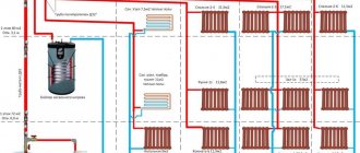
Heating boiler connection diagrams are distinguished by the method of coolant circulation.
Based on this feature, the systems are as follows:
- Gravitational . This is a natural circulation when the process of replacing heated liquid with cold masses takes place, which rises upward. The coolant returns to the boiler by gravity, under the influence of gravity. Such systems have a great advantage - they are non-volatile, so they will continue to work even in the absence of electricity.
- Forced . Here you need the help of electric circulation pumps. With this scheme for connecting the heating system to the boiler, the radiators in all rooms are heated quickly and evenly. This method is optimal when installing a heating system in a large house.
On a note. Installation of heating devices and pipelines is done in such a way as to minimize heat loss through the external enclosing structures. Heat losses in pipelines passing through unheated rooms should not exceed 10 percent of the heat consumption for heating.
According to the method of connecting pipes to radiators, the schemes are as follows:
- single-pipe, when heating devices are connected in series;
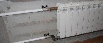
- two-pipe - parallel connection of radiators;
- bifilar - a series connection of first the first halves of the devices, then, for the coolant flow in the opposite direction, connect all their second halves.
Single pipe heating system
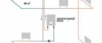
Let's look at single-pipe wiring - its pros and cons. The supply and return of the coolant in this system is created through a single pipe running in a ring. Therefore, each radiator is connected to the pipeline with both pipes.
Advantages of this wiring method:
- The installation job is simple. After all, it is easier to install one pipe than two samples.
- The heating system of the house, called Leningradskaya, is made up of polypropylene pipes. Is an inexpensive option. When metal-plastic or cross-linked polyethylene is used, then the advantage is neutralized by the cost of the fittings.
- Vertical risers with one pipe are the optimal solution when creating a gravity system in a two-story house.
Taking into account the features of single-pipe wiring and the lack of installation experience among most owners, it is recommended to assemble the Leningrad type of connection in small residential buildings or in the country.
Disadvantages of a one-pipe connection
- By mixing cool water, the temperature in the pipes decreases by 1-2 degrees after a separate radiator.
- To provide the necessary coolant consumption in heating units, the diameter of the main pipe line must be at least 25 mm along its entire length.
- When there are 5 radiators, the cross-section of the collector becomes larger, up to 32 mm.
- The enclosing radiators receive chilled water, so they heat up worse.
- The issue can be resolved by increasing the number of sections or increasing the dimensions of the panels by 10%.
Due to the increased diameter of the pipeline and the increase in the number of radiators, waste on materials increases.
When vertical wiring is done, the shortcomings are not so critical.
What pipes are needed to connect a heating boiler?
The choice of pipes is a very important stage in preparation for the installation of heating equipment.
For efficient operation of a heating system with a circulation pump, the pipes must withstand the following indicators:
- pressure - 1-2.5 kgf/sq. cm.;
- supply liquid temperature 70-75 °C;
- return temperature - 55°C.
These are parameters that are maintained during normal operation of the system, without emergency situations.
If the pump stops for some reason, the situation will develop as follows:
- for a gas, electric and diesel boiler, the thermostat will shut off the fuel supply and the operation of the water circuit will remain safe;
- For a boiler operating on solid fuel, the thermostat will close the ash pan, but combustion (smoldering) of the fuel will continue for up to half an hour, which means that the temperature of the coolant may increase.
In this situation, the performance characteristics of plastic and metal-plastic pipes that will be used for a gas, electric and diesel boiler must have operating parameters of at least 80 °C.
As for the solid fuel unit, at least 1-2 meters of the water circuit coming from the boiler must be made of steel, copper pipes or stainless steel. Steel pipes, resistant to temperature changes and hydraulic pressure, are unfortunately susceptible to corrosion, have considerable weight and an insufficiently smooth inner surface. Installation must be done by welding. The outside of the pipes is coated with paint, and such maintenance must be done regularly. Copper and stainless steel pipes do not have such problems. The only drawback is the rather high price of these products.
With natural circulation, the heating process of the coolant occurs slowly. The temperature of the liquid leaving the boiler sometimes exceeds 90°C. Therefore, the pipeline between the boiler and the expansion tank is always made of metal.
Not even the best plastic can withstand abnormal temperatures. Leakage and plastic softening are guaranteed at 130°C. Polypropylene pipes burst due to overheating.
Important. The internal diameter of the supply pipe cannot be less than 32 mm. This is necessary in order to ensure minimum hydraulic pressure during gravity heating.
In recent years, attempts have increasingly been made to hide the pipeline from view. The wiring is done not only externally, but also hidden in the walls, under the finished floor, inside plasterboard boxes. In heating systems, it is permissible to combine different types of pipes.
Advantages and disadvantages of heating a private house using a gas boiler
First, we list the undoubted advantages of gas heating:
- Affordable cost of both fuel and necessary equipment;
- High efficiency. Depending on the brand of boiler, from 80% to 90% of the gas will be used to heat the coolant. Some brands regulate the energy efficiency of their products at the level of 96-98% efficiency, this is nothing more than an advertising gimmick and manipulation of numbers;
- Compact dimensions combined with high power equipment;
- Operating a gas boiler does not require special knowledge, frequent maintenance, or careful care. Most models automatically maintain the required temperature of the coolant or indoor air;
- A gas boiler does not require systematic cleaning and filling it with fuel and unloading ash;
- Using a double-circuit boiler will not only heat the room, but also provide hot water.
However, gas heating has certain disadvantages and technical limitations:
- The functioning of the system, especially with high levels of automation, is achieved through the use of a programmable microcontroller, dependent on the power source;
- Power outages and power surges can lead to failure of heating equipment; the control board is guaranteed to burn out without proper protection;
- The room in which the gas boiler is located must be equipped with natural or forced ventilation, a chimney, and have the dimensions and location of the boiler in accordance with the standards;
- Installation of gas equipment requires appropriate permits and can only be carried out by specialists authorized for this type of work.
In addition to gas, there are a number of other heating methods that use “alternative” fuels:
- Electricity . Despite the fact that this is the most common type of energy used in everyday life, its use for heating private houses on several floors is economically unprofitable. Although modern technologies do not stand still, and some types of electric heating boilers compete with gas ones when heating a medium-sized apartment.
- Solid fuel . The price of coal and wood in some regions of Russia, in terms of the cost of kilojoules of energy released for heating, is comparable to gas. However, the need to arrange a separate boiler room and fuel storage should be taken into account. In addition, solid fuel boilers are periodically loaded and cleaned of ash. The frequency, depending on the type, ranges from several hours to several days.
- Pellet boilers . They are more efficient than conventional solid fuel ones, have a high level of automation, but their cost is incomparably higher than other heating devices, with the exception of liquid fuel ones;
- Liquid fuel . Expensive imported diesel boilers are sensitive to fuel quality. Domestic equipment is classified as universal and can be configured to consume pellets, fuel oil, and diesel. However, its level of automation, reliability of security systems and efficiency leaves much to be desired.
Equipment with a closed system with forced circulation
When the heating system does not communicate with the surrounding air and operates under pressure, such circuits are only closed.
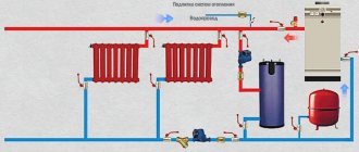
In this case, the following equipment is required to piping the boiler:
- a 100-200 watt pump, which should be installed for supply;
- membrane-type expansion tank to provide the coolant with additional volume during expansion;
- safety valve for releasing coolant if the permissible pressure is exceeded;
- an automatic air vent that will help the emerging air plug to leave the system on its own so that the coolant circulates freely throughout the circuit;
- pressure gauge - to control pressure.
These are required elements. The following options may also be included in the scheme:
- filter for gas unit;
- filter at the inlet of the heat exchanger to protect against debris;
- heat accumulator, which is advantageous to pair with solid fuel or electric boilers to save energy resources.
Requirements for a boiler room in a separate building
Boilers and related equipment may be installed in a separate building - a boiler room. The dimensions of the latter, as well as the building materials from which it is made, are regulated by the relevant SNiPs. More stringent requirements are established for a gas boiler room, since during its operation an explosion and fire of the gas-air mixture is possible. Such a project must be approved by the supervisory authorities.
For your information!
The latest change in legislation regulates the installation of a gas alarm, which automatically stops the gas supply to the boiler room when a leak is detected. This standard applies to boiler units with a capacity of more than 60 kW.
For boiler rooms that are designed for equipment running on electricity or solid fuel, less stringent requirements are put forward, since the unit in this case is not classified as explosive. Therefore, design and construction work can be done independently. When constructing a building, non-flammable or low-combustible materials are used to prevent the spread of fire in the event of a fire.
Why do you need a heat accumulator?
The heat accumulator is a tank that is connected to the boiler and water circuit. Its body is reliably covered with a heat insulator and allows it to accumulate warm water for the circuit, and then heat the room for about a day when the boiler is turned off.
How does a heat accumulator work:
- The heating unit is loaded with fuel and ignited.
- The circulation pump pumps coolant through the heat exchanger. Cold water from the bottom of the tank rushes into the boiler, and already heated water arrives at the top. Since the density of the cold and hot liquid is different, it will not mix. This will gradually fill the tank with hot water.
- If the calculations are done correctly, when the fuel burns out, the container will be filled with hot water at the required temperature. Good thermal insulation will keep the coolant hot for a long time.
- When the boiler is not functioning, the heating system continues to perform its task. The circulation pump of the heating circuit circulates the coolant through the system. Water is drawn from the top “hot zone” of the tank.
- The water returns to the return line already cooled, so the heat accumulator will gradually release the accumulated heat.
In real conditions, water is drawn into the heating system continuously. The heat accumulator accumulates “excess”, currently unclaimed heat.
A battery with a volume of 3 tons, with a supply of water at a temperature of 40-80°C, will be able to heat a house with an area of 80 sq.m. for a day. These parameters correspond to 170-175 kW hour. heat.
A regular boiler needs to be heated up to five times a day. If a heat accumulator is installed, the frequency of adding fuel to the combustion chamber will be reduced by five times. The heated water in the tank will gradually release heat energy to the radiators. A solid fuel boiler will work much more economically. This scheme for connecting a heating boiler in a private house allows you to heat the room for a long time without reducing the boiler power.
It is very beneficial to pair a heat accumulator with an electric boiler when saving energy resources is especially important.
On a note. The night tariff with a two-tariff meter is much lower than the day tariff: 2-4 times. If you turn on the electric boiler only at night, so that during the day the heat accumulator only gives off heat, you can significantly save on electricity.
Typical wiring diagrams for solid fuel boilers
The opinion that a solid fuel boiler is an obsolete unit covered with dirt and soot is wrong, isn’t it?
The complexity of controlling the combustion process in solid fuel boilers leads to high inertia of the heating system, which negatively affects the convenience and safety during operation. The situation is further complicated by the fact that the efficiency of units of this type directly depends on the temperature of the coolant. For efficient heating operation, the piping must ensure the temperature of the thermal agent is within 60 - 65 ° C. Of course, if the equipment is not integrated correctly, such heating at above-zero temperatures “overboard” will be very uncomfortable and uneconomical. In addition, the full operation of the heat generator depends on a number of additional factors - the type of heating system, the number of circuits, the presence of additional energy consumers, etc. The wiring diagrams presented below take into account the most common cases. If none of them meets your requirements, then knowledge of the principles and structural features of heating systems will help in developing an individual project.
Open type system with natural circulation in a private house
First of all, it should be noted that open gravity-type systems are considered the most suitable for solid fuel boilers. This is due to the fact that even in emergency cases associated with a sharp increase in temperature and pressure, the heating will most likely remain sealed and operational. It is also important that the functionality of the heating equipment does not depend on the availability of power. Considering that wood-burning boilers are installed not in megacities, but in areas remote from the benefits of civilization, this factor will not seem so insignificant to you. Of course, this scheme is not without its drawbacks, the main ones being:
- free access of oxygen to the system, which causes internal corrosion of pipes;
- the need to replenish the coolant level due to its evaporation;
- uneven temperature of the thermal agent at the beginning and end of each circuit.
A layer of any mineral oil 1–2 cm thick, poured into the expansion tank, will prevent oxygen from entering the coolant and reduce the rate of evaporation of the liquid.
Despite its shortcomings, the gravity scheme is very popular due to its simplicity, reliability and low cost.
Installation diagram of a solid fuel unit in an open heating system
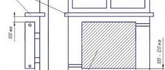
When deciding to install using this method, keep in mind that for normal coolant circulation, the boiler inlet must be at least 0.5 m below the heating radiators. The supply and return pipes must have slopes for normal coolant circulation. In addition, it is important to correctly calculate the hydrodynamic resistance of all branches of the system, and during the design process try to reduce the number of shut-off and control valves. The correct operation of the system with natural coolant circulation also depends on the installation location of the expansion tank - it must be connected at the highest point.
Closed system with natural circulation
Installing a membrane-type expansion tank on the return line will avoid the harmful effects of oxygen and eliminate the need to control the coolant level.
Design of membrane expansion tank
When deciding to equip a gravity system with a sealed expansion tank, consider the following points:
- the capacity of the membrane tank must contain at least 10% of the volume of the entire coolant;
- a safety valve must be installed on the supply pipe;
- the highest point of the system must be equipped with an air vent.
Additional devices that are included in the boiler safety group (safety valve and air vent) will have to be purchased separately - manufacturers very rarely equip units with such devices.
The safety valve allows the coolant to be discharged if the pressure in the system exceeds a critical value. A normal operating indicator is considered to be a pressure of 1.5 to 2 atm. The emergency valve is set to 3 atm.
You will learn more about this system in our next article:.
Features of systems with forced coolant movement
In order to equalize the temperature in all areas, a circulation pump is integrated into the closed heating system. Since this unit can provide forced movement of the coolant, the requirements for the level of installation of the boiler and compliance with slopes become negligible. However, you should not give up the autonomy of natural heating. If a bypass branch, called a bypass, is installed at the boiler outlet, then in the event of a power outage, the circulation of the thermal agent will be ensured by gravitational forces.
The use of a bypass will allow, if necessary, to switch to the natural method of coolant circulation
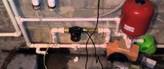
The electric pump is installed on the return line, between the expansion tank and the inlet fitting. Thanks to the lower coolant temperature, the pump operates in a more gentle mode, which increases its durability.
Installing a circulation unit on the return line is also necessary for safety reasons. When water boils in the boiler, steam may form, the entry of which into the centrifugal pump can completely stop the movement of the liquid, which can lead to an accident. If the device is installed at the inlet of the heat generator, it will be able to circulate the coolant even in the event of emergency situations.
Connection via manifolds
If it is necessary to connect several parallel branches with radiators, a water heated floor, etc. to a solid fuel boiler, then balancing of the circuits is required, otherwise the coolant will follow the path of least resistance, and the remaining parts of the system will remain cold. For this purpose, one or more collectors (combs) are installed at the outlet of the heating unit - distribution devices with one input and several outputs. Installation of combs opens up wide possibilities for connecting several circulation pumps, allows you to supply a thermal agent of the same temperature to consumers and regulate its supply. The only disadvantage of this type of piping can be considered the complication of the design and the increased cost of the heating system.
Manifold piping of a solid fuel boiler
A separate case of manifold piping is a connection with a hydraulic arrow. Its difference from a conventional collector is that this device acts as a kind of intermediary between the heating boiler and consumers. Made in the form of a large-diameter pipe, the hydraulic arrow is installed vertically and connected to the inlet and pressure pipes of the boiler. In this case, consumers are inserted at different heights, which allows you to select the optimal temperature for each circuit.
Installation of emergency and control systems
Emergency and control systems serve several purposes:
- protection of the system from depressurization in the event of an uncontrolled increase in pressure;
- temperature control of individual circuits;
- boiler protection from overheating;
- prevention of condensation processes associated with large differences in supply and return temperatures.
To solve system safety problems, a safety valve, emergency heat exchanger or natural circulation circuit is introduced into the piping circuit. As for the issues of regulating the temperature of the thermal agent, thermostatic and controlled valves are used for these purposes.
Trim with three-way valve
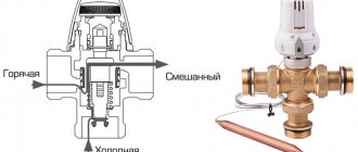
Three-way mixing valve design
A solid fuel boiler is a periodic heating unit, so it is at risk of corrosion due to condensation that falls on its walls during heating. This is due to the ingress of too cold coolant from the return into the heat exchanger of the heating unit. The danger of this factor can be eliminated using a three-way valve. This device is an adjustable valve with two inputs and one output. Based on a signal from the temperature sensor, the three-way valve opens the hot coolant supply channel to the boiler inlet, preventing the formation of a dew point. As soon as the heating unit enters operating mode, the supply of liquid in a small circle stops.
Trim diagram with three-way valve
A fairly common mistake is to install a centrifugal pump before a three-way valve. Naturally, with the valve closed, there can be no talk of any liquid circulation in the system. It is correct to install the pump after the adjusting device.
A three-way valve can also be used to regulate the temperature of the heating agent supplied to consumers. In this case, the device is set to work in the other direction, mixing cold coolant from the return to the supply.
Circuit with buffer capacity
Diagram of a heating system with a buffer tank
The low controllability of solid fuel boilers requires constant monitoring of the amount of firewood and draft, which significantly reduces the convenience of their operation. Installing a buffer tank (heat accumulator) will allow you to load more fuel without worrying about possible boiling of the liquid. This device is a sealed tank that separates the heating unit from consumers. Due to its large volume, the buffer tank can accumulate excess heat and transfer it to radiators as needed. The mixing unit, which uses the same three-way valve, will help regulate the temperature of the liquid coming from the heat accumulator.
Trim elements ensuring the safety of the heating system
Emergency circuit harness
In addition to the safety valve mentioned above, protecting the heating unit from overheating is achieved using an emergency circuit through which cold water from the water supply is supplied to the heat exchanger. Depending on the design of the boiler, the coolant can be supplied directly to the heat exchanger or to a special coil installed in the working chamber of the unit. By the way, it is the last option that is the only possible one for systems with filled antifreeze. The water supply is carried out using a three-way valve, which is controlled by a sensor installed inside the heat exchanger. The “waste” liquid is discharged through a special pipeline connected to the sewer system.
Connection diagram for an indirect heating boiler
Connection diagram for an indirect heating boiler
Piping with connection of a boiler for hot water supply can be used for heating systems of all types. To do this, a special heat-insulated container (boiler) is connected to the water supply and hot water supply system, and a coil is installed inside the water heater, which is cut into the heating agent supply line. Passing through this circuit, the hot coolant transfers heat to the water. Often, an indirect heating boiler is also equipped with heating elements, thanks to which it becomes possible to obtain hot water in the warm season.
A three-way valve can also be used in a piping circuit for an indirect heating boiler. Read more about this in our material:.
Video: Tying a solid fuel boiler
How to choose strapping elements
When choosing a pump, you need to pay attention to the thermal load on the circuit. Here it is important to calculate the difference between the supply and return water temperatures.
The formula is as follows:
- Q=0.86xR/Dt,
- where Q is the pump performance indicator (cubic meters per hour),
- R - boiler power,
- Dt is the temperature difference.
For example, with a boiler power of 20 kW and a heating system temperature of 80/60oC, a pump is needed with the following performance characteristics:
- 0.86x20(80-60)=0.86 m3/h.
A pump with stepwise power adjustment performs well. It will be able to provide such a level of performance that the radiators throughout the circuit are evenly heated.
A parameter such as coolant pressure, which is measured in meters of water column, can be ignored. In a heating system, the number of floors in the building or the floor on which the circulation pump is located does not matter. The minimum pump value is 2 meters. Devices with this parameter cope well with the movement of coolant in the water circuit of an apartment building with high hydraulic resistance. When piping a heating boiler, these points need to be remembered.
What to pay attention to when installing a membrane tank:
- First of all, it is important to choose the volume of the tank. It should be 1/10 of the volume of coolant in the water circuit. There is an easy way to calculate this. If the heating system has aluminum or bimetallic radiators, then 1 kilowatt of boiler power requires 15 liters of coolant.
- The tank can withstand temperatures up to +120 C.
- The operating pressure of the device often does not exceed 1.5 bar. Sometimes there is a need to increase it. To do this, pump air into the tank using a bicycle pump.
How to select security group elements:
- The valve has an upper limit of permissible pressure of 2.5 bar.
- A pressure gauge must be selected with a pressure of 4 atmospheres.
How to arrange the strapping elements:
- The circulation pump is placed in front of the combustion chamber (in front of the heat exchanger), where the temperature is lower.
- The valve and pressure gauge are mounted at the outlet of the heat exchanger, in the place where the pressure begins to increase.
- The expansion tank is mounted in any part of the circuit, but not next to the pump (pressure fluctuations will lead to wear of the tank).
How to tie solid fuel boilers
The connection diagram for a wood-burning heat generator is designed to solve 3 problems (in addition to supplying the batteries with coolant):
- Preventing overheating and boiling of the TT boiler.
- Protection against cold “return” and excessive release of condensate inside the firebox.
- Work with maximum efficiency, that is, in full combustion mode and high heat transfer.
Note. For units with a cast iron heat exchanger, protection against temperature shock, leading to cracking of sections, is important. The phenomenon occurs in a closed system when water circulation stops due to a power outage. After supplying electricity, the cooled coolant sharply cools the cast iron, resulting in cracks.
The presented wiring diagram for a solid fuel boiler with a three-way mixing valve allows you to protect yourself from condensation in the firebox and bring the heat generator to maximum efficiency mode. How it works:
- While the system and heater are not warmed up, the pump drives water through the small boiler circuit, since the three-way valve is closed on the radiator side.
- When the coolant heats up to 55-60 degrees, the valve set to the specified temperature begins to mix in water from the cold “return”. The heating system of a country house is gradually warming up.
- When the maximum temperature is reached, the valve completely closes the bypass, all water from the TT boiler goes into the system.
- A pump installed on the return line pumps water through the jacket of the unit, preventing the latter from overheating and boiling. If you put the pump on supply, the chamber with the impeller can fill with steam, pumping will stop and the boiler is guaranteed to boil.
Recommendation. We do not recommend tying plastic pipes around wood-burning boilers, at least on the supply side. It is better to use copper, galvanized steel or stainless steel.
The principle of heating using a three-way valve is used for piping any solid fuel heat generators - pyrolysis, pellet, direct and long-term combustion. The exception is gravity distribution, where the water moves too slowly and does not provoke condensation. The valve will create high hydraulic resistance, preventing gravity flow.
If the manufacturer has equipped the solid fuel unit with a water circuit, the coil can be used for emergency cooling in case of overheating. Please note: the fuse on the safety group is triggered by pressure, not temperature, and therefore is not always able to protect the boiler.
A proven solution is to connect the DHW coil to the water supply through a special thermal relief valve, as shown in the diagram. The element will be triggered by a temperature sensor and at the right moment will pass a large volume of cold water through the heat exchanger.
Using the Buffer Capacity
The best way to increase the efficiency of a TT boiler is to connect it to heating through a buffer tank. At the inlet of the heat accumulator we assemble a proven circuit with a three-way mixer, at the outlet we install a second valve that maintains the required temperature in the batteries. Circulation in the heating network is ensured by a second pump.
A balancing valve on the return line is needed to adjust the performance of the pumps
What we gain thanks to the thermal accumulator:
- the boiler burns at maximum and reaches the declared efficiency, fuel is used efficiently;
- the likelihood of overheating is sharply reduced since the unit dumps excess heat into a buffer tank;
- the heat accumulator plays the role of a hydraulic arrow; several heating branches can be connected to the tank, for example, radiators of the 1st and 2nd floors, floor heating circuits;
- a fully heated tank maintains the operation of the system for a long time when the wood in the boiler firebox has burned out.
Note. Factory heat accumulators are often equipped with electric heaters - heating elements, which maintain the water temperature in the upper zone of the tank. How to make a connection between the heater and the tank, watch the video:
TT boiler and storage water heater
In order to load an “indirect” boiler using a wood heat generator, you need to embed the latter into the boiler circuit, as shown in the picture. Let us explain the functions of individual elements of the circuit:
- check valves prevent the coolant from flowing in the other direction along the circuits;
- the second pump (it is enough to take a low-power model 25/40) provides circulation through the spiral heat exchanger of the water heater;
- the thermostat turns off this pump when the boiler reaches the set temperature;
- An additional air vent prevents the supply line from becoming aired, which will be above the standard safety group.
In a similar way, you can connect the boiler to any boiler that is not equipped with an electronic control unit.
Mini boiler rooms
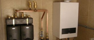
Nowadays, boiler models are produced equipped with an expansion tank, pump, valve and pressure gauge. These can be heating elements, electric, diesel, gas units with forced draft. These units can be called mini-boiler rooms. Thus, safety valves in the electric heating circuit of a private house with a pump are mounted directly on the heat exchanger together with the heating element. This design allows you to quickly discharge excess coolant if it boils when the pump is stopped.
The connection diagram of the boiler to the heating system in this case is not complicated. You only need to install two ball valves, which can be used to shut off the boiler if necessary. Repairing the unit or any preventive maintenance will not cause difficulties.
Gas boiler power calculation
As a rule, when ordering a gas boiler, most craftsmen, without hesitation, determine the required power value as 1 kW per 10 m2 of heated area + 15% as a reserve to avoid peak loads. However, there are several climatic zones on the territory of Russia, so if you are calculating the heating system in a private house from a gas boiler with your own hands, then it is more advisable to derive the power of the equipment based on the following formula:
MK=S×UMK/10,
Where:
- MK – boiler power;
- S is the area of the cottage that needs to be heated;
- UMK – specific power of the boiler.
UMK – taken as a coefficient depending on the zone where the house is located:
- Southern regions - 0.7-0.9;
- Central Russia - 1.0-1.2;
- Zones with a sharply continental climate - 1.2-1.5;
- Northern and Far Eastern regions - 1.5-2.5.
The presented calculation is valid for buildings of 1 floor, erected according to standard designs and in strict accordance with SNiPs. Calculation of the power of heating equipment for individual buildings is carried out using a different formula:
MK=Qt×Kz,
Where:
- Qt—calculated heat loss of the structure, kW;
- Kz - safety factor from 1.15 to 1.25, that is, 15-25%.
Calculation of heat loss of a structure is carried out using the following simplified formula:
Qt=V×Pt×k/860,
Where:
- V – volume of the heated room;
- Pt is the difference between the temperature outside and inside the building;
- K – dissipation coefficient, depends on the structural materials of the building and the thickness of the insulation.
The dispersion coefficient is assumed to be as follows:
- Structures made of wooden beams or rounded logs without insulation (lack of thermal insulation) - 3.0-3.5;
- Buildings with walls made of single brickwork, ordinary windows and an uninsulated roof (poor thermal insulation) - 2.0-2.9;
- Buildings with walls made of double brickwork, double wooden windows and a roof protected with glass wool (medium thermal insulation) - 1.0-1.9;
- External walls and attic spaces are insulated with polystyrene foam or mineral wool, metal-plastic energy-saving windows with double glazing are used (well-insulated structures) - 0.6-0.9.
Equipment with open gravity system
With an open gravity system, the entire load falls on the open expansion tank.
It performs the following functions:
- takes away excess amount of coolant;
- compensates for increased pressure;
- removes air and hot steam when the coolant boils.
The volume of the tank should not be less than 10 percent of the coolant volume. More is possible. Install it at the top point of the circuit, where the accelerating manifold ends. From the tank, the filling goes back to the heat exchanger, with a slope that ensures that air pockets are removed and the coolant moves by gravity.
Cold water is usually poured through an open expansion tank to compensate for evaporation.
Ventilation and sewerage
The boiler room must have natural ventilation. The ventilation shaft runs parallel to the chimney, but has a smaller cross-section.
The opening of the ventilation shaft is equipped with a forced exhaust; its role is as follows:
- Attracting air from other rooms, which is necessary for combustion, but in the boiler room itself it quickly burns out.
- Removing combustion products from the premises.
The boiler room must have a sewer outlet, since it is periodically necessary to remove the water jacket in the boiler and reset the safety valve, and sometimes reset the entire system.
Hot water supply system connection diagram
Often an additional hot water supply system is connected to the heating boiler.
Different methods can be used here:
- With a two-pipe dead-end circuit, heating devices are connected between bottlings. The big disadvantage is that nearby radiators will be hotter, and those farther away will be colder, so this system requires balancing.
- When connecting a double-circuit gas boiler, a separate heat exchanger is needed to organize DHW. Here the scheme is simple: cold water goes through the heat exchanger and is sent further to the plumbing fixtures.
- If a double-circuit boiler is connected to the heating system using a forced circulation circuit, then the radiators are installed in a parallel manner so as not to cut the coolant supply pipe.
- When using a scheme with a single-circuit boiler to obtain hot water in a private house, you need to connect an indirect heating boiler. In this case, the coolant will transfer its thermal energy to the boiler heat exchanger. In summer, the heating circuit is switched off.
- The classic gravity heating system is based on the height difference between the heat exchanger and radiators.
- If a heat accumulator is attached to a solid fuel boiler, the temperature of the radiators is regulated by a three-way valve with a thermostat.
Option for implementing a heating system for a double-circuit boiler:
- the small circuit into which the circulation pump is built is closed by a heat exchanger with a hydraulic arrow;
- the next position is manifold wiring to independent circuits: 2 radiators and 4 underfloor heating circuits.
Primary requirements
The main task is to connect the boiler and all radiators in the most efficient way. It is important to take into account a number of requirements:
- The routing should be laid along the route with the shortest length.
- The hydraulic resistance of pipes, valves and fittings should be reduced whenever possible.
- It is necessary to think through and arrange all functional units on the line with a minimum number of bends, tees and valves. This refers to the safety group, expansion tank, circulation pump, fittings for draining and filling the system, etc.
- Pipes are selected based on the performance characteristics of the material and the heating system.
- The diameter of the pipes is calculated to minimize pressure losses on the one hand and reduce the volume of the pipeline on the other.
Wall type
Installation of a wall-mounted boiler:
- Initially, you need to protect the part of the wall on which the boiler will be installed. For this purpose, fire-resistant material is used. The gap between the wall and the protective layer is about 45mm.
- Prepare the boiler for installation. Clean the walls of the inlet openings with strong water pressure.
- Install the filter with shut-off valves on both sides onto the water supply pipe.
- Bring up the chimney. There are some requirements for it, which can be found in the boiler operating manual. It is better to use a cylindrical chimney made of steel with the possibility of cleaning.
- Check traction. If it is weak, the gas supply should stop due to automatic operation.
- Connect the boiler to the gas pipeline using a steel pipe and a drain designed for this purpose. This is carried out by a specialist from the gas service.
- Connect the boiler to the electrical network and connect the overload protection circuit breaker.
