Air pockets, microscopic bubbles and various contaminants can significantly disrupt the functioning of the heating system and also reduce its efficiency. The air and sludge separator allows you to eliminate all of the above factors that complicate the operation of the heating system.
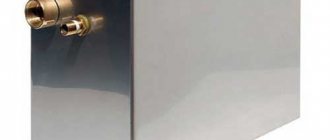
Separator of microbubbles and sludge Flamcovent Clean 22 mm - 2" (Netherlands).
The presence of air and air pockets in the heating system creates the following problems for the operation of its elements:
- Reduced heat transfer from heating devices;
- Premature wear of circulation pump parts (bearings, blades), as well as a decrease in its operating efficiency;
- The internal surfaces of radiators, pipes and heating boilers are subject to accelerated corrosion.
The only device that can completely solve the problem of air jams is an air separator.
Flamcovent 3/4″ model without sludge trap. Cost about 2,000 rubles.
A coolant based on ordinary tap water contains a large amount of dissolved air, which, when heated, is released and turns into many small bubbles. The largest number of bubbles is formed in the place where the coolant is heated, i.e. in the heating boiler. After this, the bubbles spread along the heating circuit, where they dissolve in the coolant as it cools.
By installing an air and sludge separator in the supply, immediately after the boiler, bubbles formed in the boiler can be removed. Thus, the coolant entering the heating circuit becomes completely free of oxygen.
In addition, the deaerated coolant will absorb oxygen in those parts of the heating system where it is present. For example, if the walls of polymer pipes do not have an anti-diffusion coating, they will in any case allow oxygen into the system in small quantities. This oxygen is absorbed by the deaerated coolant and delivered to the separator, where it is removed. In this way, the heating system can be completely ventilated.
The disadvantages of the air separator include the fact that, by creating resistance to the flow of coolant, it affects the hydraulics of the entire heating system.
Introduction
It is known that when starting heating systems, big problems are caused by air cavities remaining inside and solid particles or sludge circulating in the flow.
The presence of air cavities and plugs automatically means a high concentration of dissolved gases in the water, which can cause increased corrosion and erosion processes, problems with cavitation, and a decrease in the efficiency of pumps, fittings and heat exchangers. The presence of gases, in turn, stimulates the appearance of solid particles in the coolant. By settling in places with the lowest speed, layers of particles sharply reduce the efficiency of heat transfer. Once they get into pumps and control valves, they quickly damage the equipment. Corrosion processes under a layer of deposited sludge are difficult to slow down. Considering that when systems are periodically stopped for maintenance, tons of particles settle at the bottom of pipelines, this process each time creates new sources of pitting corrosion. Currently existing methods and equipment are aimed largely at treating water entering the system /1/
At the same time, it is sometimes not taken into account that systems cannot be perfectly sealed, gas flows into systems can be quite large even in closed systems, and degassing of large and complex systems can take a long time. In this case, as in the case of start-up, problems can arise even if the quality of the make-up water is normal.
It can also be noted that in case of design or configuration errors, areas of negative pressure may appear in some areas of the systems. In this case, conditions are created for the emergence of stable gas flows into the system.
It is generally accepted that in most cases, installing a sufficient number of air vents will ensure degassing of systems during operation. To evaluate the effectiveness of their use, we recall that the gases in the system are in three states: in the form of cavities, bubbles and microbubbles, and in a dissolved state /2/. The work of air vents is mainly related to the first form, because Only the appearance of a significant volume of gas in the upper part of the air vent activates the mechanism for its removal. The bulk of bubbles and microbubbles moving in the flow simply do not have time to rise into the air vent chamber. Therefore, air vents should be located at the highest points of the system, in places of local elevations and on radiators. In complex systems it is necessary to install a large number of these devices. At the same time, the air vent, along with the expansion tank, is one of the most vulnerable elements. Almost all differences in designs and prices are associated with varying degrees of reliability and protection of air vents from blocking them with bubbles or depressurization when dirt particles get inside the trigger mechanism.
In complex systems with a large number of air vents installed in hard-to-reach places, it is difficult to check the quality of their work. The low price (and sometimes quality) of air vents often does not compensate for the complexity of maintenance and losses from problems that arise. Air cavities that are not removed in time can be reabsorbed by water when the operating mode of the system changes, further stimulating corrosion. Water leaking out or air getting inside when the air vent is depressurized can quickly damage any system. Automatic float air vents remove air pockets and bubbles as they appear in automatic mode /3/. Air vents of this type provide better tightness and are better protected from blocking and depressurization when dirt gets into them.
Mud collectors installed inside the system circuit are usually equipped with mesh with large cells. Otherwise, they quickly become clogged and the circulation flow can be completely blocked. Thus, we can assume that inside the system, as a rule, there are no devices that perform processes of fine cleaning of the coolant from sludge and its amount can increase as a result of chemical reactions or detachment of deposits.
Video
Insufficient tightness of the heating system, natural diffusion, corrosion of steel and cast iron elements are the reason for air and solid particles entering the coolant.
This leads to a decrease in the service life of radiators, pipes, heat exchangers, pumps, and other elements and a decrease in the efficiency of the system. The problem is relevant for both large centralized and autonomous heating systems. Air and sludge in the coolant:
- Reduce heat transfer.
- Cause chemical and mechanical destruction of heating system elements.
- Lead to the formation of traffic jams.
Installing air vents, drain valves, mud traps, and removing air and suspended matter from the coolant before filling it into the system is not effective enough.
Draining the coolant from the taps removes cavities and plugs; air vents do not remove microbubbles. Mud collectors do not perform fine cleaning; the bulk of the suspended matter remains in the coolant.
Purpose
So, why do you need a hydraulic arrow in a heating system?
The purpose of installing a hydraulic distributor in a heating system is to separate coolant flows, as well as to protect boiler equipment.
Let's consider the main specific situations in which this device can be useful in a heating system:
- When it is necessary to create two or more heating circuit circuits with different coolant flow rates. For example, a docked circuit requires more flow than the main one from the boiler. In this case, there are two ways to solve the problem: increase the power and circulation of the main circuit, which will not be economically justified and will lead to a rapid depletion of the equipment’s life. Another way is to install a hydraulic arrow, which will regulate the flow.
- In heating schemes that include boilers, heated floors and several circuits, a hydraulic separator will help to avoid the negative impact of these systems on each other. When turning any of the elements on and off, the overall balance of the system will not be disrupted.
- If there are several circuits (from one boiler), each of which has its own circulation pump. The hydraulic arrow does not allow them to oppose each other. The devices operate smoothly, the coolant is distributed evenly and in sufficient quantities in all circuits.
- There are several boilers that are combined into a single heating circuit. You can’t do this without installing a hydraulic arrow.
- Maintainability is another plus that appears when installing a hydraulic distributor. The device makes it possible to maintain the functionality of all circuits, except for the one that needs to be turned off.
- In some situations, equipment may be subject to temperature changes. A sudden supply of cold liquid to a heated element of the system can lead to cracks and failure. Cast iron heat exchangers, radiators, etc. are especially sensitive to such changes. This happens when heating is started, during repair work, emergency shutdown, etc.
These are the main functions that the hydraulic gun performs. During operation of the device, sediment accumulates in its lower part from impurities contained in the coolant (scale, rust, sand, and other dirt).
A special tap is installed here to remove sediment, and many attribute this to the additional advantages that the hydraulic distributor provides.
After all, cleaning the liquid from impurities has a beneficial effect on each element of the system and extends their service life.
In addition, the device is equipped with the ability to bleed air dissolved in water. If it accumulates in radiators, it leads to a decrease in heating efficiency. So the hydraulic separator is also an air vent.
In the warranty card for some types of equipment you can read that the manufacturer is responsible and is ready to accept faulty equipment only if there is a hydraulic separator in the system.
Causes of excess air
There are many reasons for the appearance of air; it is quite difficult to completely avoid this phenomenon. Still, the factors that cause air pockets to form in the heating system should be studied in order to minimize their impact on the system.
Most often, air enters the system:
- if the heating was initially installed incorrectly;
- if the rules for filling the heating circuit with water are not followed;
- if the tightness of the connection of individual elements of the system is broken;
- when the system lacks or incorrectly uses air exhaust devices;
- after repair work;
- when replacing the lost volume of coolant with cold water.
Improper installation of the heating system leads to its airing in cases where the pipes are laid with an incorrect slope, form loops, etc. It is best to track such areas at the design stage of autonomous heating.
Filling the circuit with water should be done according to the principle: the larger the volume of coolant, the lower the rate of its entry into the system. If water enters too quickly, in certain areas it can become a spontaneous version of the water seal, preventing the natural process of displacing air from the circuit.
Leaks often occur at the junctions of pipes and radiators. Sometimes the crack is so small that the water escaping from it evaporates almost immediately. The hole remains unnoticed, and air gradually penetrates through it, replacing the lost volume of water.
Since in one way or another the circuit may still become air-filled, when designing the heating system, it is necessary to provide for the installation of special devices designed to bleed air from the heating system. If you already have such air vents, but they do not give the desired effect, some of them may be broken and require replacement.
It also happens that air removal devices are ineffective due to their incorrect installation or insufficient quantity. It is inevitable that air will enter the system after it is repaired. In this case, it will be necessary to carry out de-airing measures.
If part of the coolant volume is lost, it must be replenished. Fresh water, unlike what is already in the system, contains a certain amount of air dissolved in it. When heated, it releases in the form of small bubbles and accumulates, forming plugs.
If fresh coolant has been added to the system, after a while it will not hurt to make sure that it is not air-filled anywhere.
Hydraulic arrow for heating operating principle, purpose and calculations
A traditional heating system without the use of special components may have certain disadvantages. Its functioning without important modifications and adjustments will become unbalanced. A correctly mounted hydraulic heating arrow helps to remove the imbalance.
It is important to use this unit to reduce the level of thermal fluctuations inside the boiler and create coordinated operation of the circulation pumps
In current conditions, the demand for a hydraulic needle is evident in most heating systems. Functionally, it is a compensation chamber that provides communication between independent heating circuits.
- The need for waterworks equipment
- What does a hydraulic separator look like?
- The principle of operation of a node in the system
- Additional functions
- Carrying out calculations
- Special conditions
- How to properly combine a manifold with a hydraulic arrow
The air vent is an invisible worker of the heating system
Any engineering system consists of a large number of parts, assemblies, and equipment. Each element, be it a boiler or a regular air vent, performs its own function, ultimately affecting the overall reliability and durability of the system. We will talk about such a simple device at first glance as an air vent.
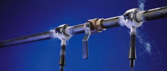
Rice. 1. Corrosion of steel pipes
Who will be indifferent to the pieces of dismantled pipelines ( Fig. 1
) or heating devices?
As a rule, this makes an indelible impression on ordinary people, in whose eyes the question freezes: “How did something even work?!” Rice. 2. Mayevsky crane ( R .400)
Fig.
3. Automatic air vent VALTEC VT .502
In addition to those listed, there are also special radiator air vents ( Fig. 4
), also related to automatic ones.
Rice. 4. Radiator automatic air vent V ALTEC VT.501
When installing a heating system, the air vent is installed at the highest point of the system. Often you have to place it right under the ceiling. In standard designs, the spool outlet is located on top of the device ( Fig. 5
), which sometimes makes it difficult to install and maintain in confined spaces.
But this does not apply to the VT.502 air vent ( Fig. 3
). VALTEC pays special attention to adaptation
Rice. 5. Lever air vent design
Unlike standard automatic air vents, VALTEC VT.502 has a more advanced design, due to which the number of parts is reduced and there are no hinged parts. This solution ensures high reliability and extends the service life of the device.
Rice. 6. Design of air vent VT.502
The operating principle of the gas release device of an automatic air vent is somewhat reminiscent of the well-known wheel nipple (car, bicycle). They pressed the spool - air came out, released it - the valve closed. Only in the case of a nipple, excess gas is removed manually, and in the case of an air vent - automatically, due to the mechanical action of a bracket attached to the float. The air-gas environment releases itself.
Rice. 7. Shut-off valve V ALTEC
VT.539
The air vent, like a safety valve or expansion tank, is an important element of system safety, therefore the overall reliability of the heating system depends on the correct selection, installation and subsequent operation.
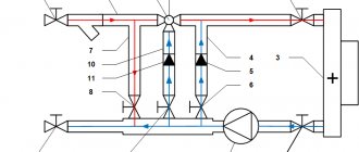
The principle of operation of the hydraulic arrow
Let's look at the operating principle of the hydraulic separator. Since there is nothing inside the pipe of the device, it is clear that the regulation of the coolant is carried out due to physical laws. How it works:
When the equipment is just starting up, the temperature of the coolant is not yet sufficient to somehow heat the room, and the circulation pumps are already dispersing it through the radiators. The water, reaching the hydraulic arrow, is directed downwards and rotates in a small circle and the boiler works for itself, quickly increasing the temperature of the coolant.
Hydraulic processes occurring in a hydraulic arrow
After the balance in the supply and return temperatures is restored, the flows practically do not mix, and the hydraulic arrow only performs the functions of collecting impurities and air from the liquid. But in practice, such an equilibrium is practically unattainable and short-lived, so the presence of a hydraulic arrow will always be justified.
If for some reason the system flow increases, and the ducts in the boiler are smaller in diameter and simply cannot provide a higher flow. Then the water in the hydraulic arrow is mixed (the required volume of liquid is added from the return to the supply) and each element of the system receives as much as it requires - the boiler is smaller, the pipeline branches are larger.
Long-burning heating boilers especially urgently need to install a hydraulic arrow, since they have several combustion modes (from ignition to extinction) and at each stage of operation it is necessary to create stable conditions of pressure and temperature.
Installation recommendations
Requirements for installing a separator in a heating system.
An air and sludge separator is installed in the supply immediately after the boiler. As noted above, the largest number of bubbles are released from water when it is heated in a boiler. If they are not removed immediately, they will dissolve in the cooling water.
The device is installed in front of the circulation pump. This prevents air bubbles from entering the pump housing, which in turn reduces wear on pump parts.
Separators for degassing and sludge removal
Fig.1 Separator
The separators that appeared in recent years in the Russian Federation began to be produced in Europe more than 30 years ago and have become a standard element for degassing and removing sludge from heating and water supply systems. In addition to removing plugs, separators remove microbubbles and sludge particles from the water flow and combine the functions of air vents, filters and deaerators. Separators do not require consumables, energy or maintenance, operate for several decades, and have a simple and reliable design without moving parts.
The universal separator is a metal cylinder with an air vent at the top, a sludge discharge valve at the bottom and a stationary mechanical separating element inside (Fig. 1). An element inside the separator ensures rapid transport of microbubbles to the top and deposition of insoluble particles below as the water flow passes through the separator. The separator's automatic float air vent removes air accumulated at the top, and periodic sludge removal is carried out manually using a ball valve at the bottom of the separator. In both cases, the system does not depressurize. When the system is initially filled with water, large air bubbles are quickly removed using a special valve in the air vent housing. Separators are installed vertically.
Separators from different companies, as a rule, differ in different types of separating elements. In Pneumatex separators (Switzerland), such an element uses a petal spiral (spirals) with a profiled surface made of stainless steel, installed vertically along the axis of the separator (Fig. 1). The mechanisms for extracting gases and solid particles may also be different. As a rule, the gravitational mechanism of particle sedimentation and bubble sublimation is used. To enhance the effect, the flow speed inside the separator is reduced (the cross section is increased), and the flow is laminarized. Some models use a centrifugal effect to spin the flow inside the separator. When using working elements with a large area, the mechanism of sorption of microbubbles on the surface is activated with their further merging into larger bubbles and floating up.
The range of application of separators is quite wide.
For example, Pneumatex industrial separators (standard sizes DN 50 – 600 mm) are capable of processing flows in the range of 5 – 2000 m 3 /h. The housings of industrial separators are made of steel.
Brass separators for small objects (standard sizes DU 20 – 40 mm) process flows up to 5 m 3 /h. All brass separators are assembled from basic elements and can be easily transformed.
How does a grain cleaning separator work?
The main working elements of the equipment are:
- reception area (grain bin);
- feeding device (feeds grain into the hopper);
- upper and lower casing of lattice type;
- aspiration channels (2 pcs) are needed for primary and final cleaning;
- precipitating type chambers, housing drive.
Simple separators
They serve to calibrate grain into two fractions according to one defining characteristic. The working elements of these separators include grid sheets, trier-type cylinders, blowers and air supply channels.
Complex separators
They consist of several simple devices, which allows you to calibrate grain of more than 2 fractions according to several criteria. The connection diagram of a complex separator can be parallel, serial or combined. It depends on the type of raw material.
The trier screw separator comes in cylindrical and disk types. It divides the grain mixture into wild oats and cockle (fractions with long and short sizes, respectively). The cylindrical trier is equipped with a rotating cylinder with perforated recesses on the inner surface. During rotation, the grains, which correspond to the dimensions of the recesses in the cylinder, rise along its walls and fall into the receiving chute of the screw conveyor. In the disk version of the trier, the raw materials are separated on rotating cast iron disks, falling into the cells.
What determines the effective operation of a separator?
The accuracy of grain selection in the air flow is approximately 3%. For smooth operation of the unit, it is important to apply the permissible load to the separator, take into account the air flow speed and its distribution over the cross section of the channel.
Thanks to the aerodynamic apparatus, high-quality preparation of grain crops is ensured. The device parameters allow you to work with wet and clogged raw materials and carry out primary and secondary cleaning.
The installation is easily adjusted to the required grain crop. An important factor is the ability to choose a unit with the required productivity (from 4 t/h to 70 t/h) for a small or large enterprise and an affordable price.
The principle of operation of the grain separator
The grain mass is loaded into the receiving hopper and then evenly distributed over the grates. After the product is evenly distributed, it is fed into the aspiration cleaning channel to undergo primary cleaning. At this stage, in the channel, light and straw-type impurities are blown by the air flow into the settling chamber. From this chamber, the collected waste is removed from the installation using a screw conveyor. Next, the semi-cleaned grain moves through the upper sieve-type housings. The grain crop is cleaned from large impurities.
On the lower body of the sieve type, the grain is divided into three streams, which pass along the tiers of the grates. Thus, a small fraction of impurities is also extracted from the grain mixture. After these two stages of cleaning, the grain passes through the aspiration channel ─ this is the final cleaning of the grain. After this, the product is sent to the next stage of processing.
Separators for heating systems
Devices made of anti-corrosion brass and stainless steel;
Quick removal of dirt particles and air pockets;
Options for any engineering systems, including those with high temperatures and pressure;
Various connection options;
Ability to work in an aggressive environment;
Prevents cavitation and corrosion;
The ability to significantly increase the service life of heating, water supply and cooling systems.
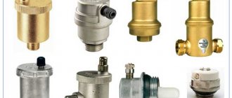
Gas/air microbubble separators, sludge separators, gas/air and sludge microbubble separators are divided into three types.
Just a gas/air microbubble separator
– removes
air microbubbles
from the heating system.
Sludge separator
– the smallest particles with a size of 5 microns (=0.005 mm) are separated and removed, but the pressure in the heating system does not drop, even with a large accumulation of dirt.
Separator of microbubbles of gas and sludge - removes both air and contaminant particles.
Separators are manufactured
with different types of connections, usually small diameters with threaded connections, and from 50 mm already with flanges or for welding.
The most advanced separation and deaeration systems for heating systems
developed in Europe, such companies as
Spirovent (Spirovent) Netherlands - Holland and Flamco (Flamco) Netherlands,
are leaders in the production and sales
of separators, non-blocking air vents, automatic make-up systems and deaerators of various
types
for heating systems, hot water supply
and
cooling systems.
A distinctive feature of the products produced is reliability, service throughout Russia, price-quality ratio at the highest level. And the payback of this equipment is guaranteed, even if you don’t notice it!
Heating and hot water supply systems have “invisible enemies”. These are micro-bubbles of air and particles of sludge,
destroying pipes from the inside.
Tracking their appearance is like looking for a needle in a haystack. However, there are special automatic devices for this - gas and sludge separators.
How are separators constructed?
Each gas microbubble separator
has a metal body with a ventilation valve and an eyelet for fastening.
Inside there is an air chamber, a separating drum,
and an outlet device for cleaning or washing.
They operate as follows: the flow, passing through the separator,
slows down.
As a result, air bubbles
rise upward.
They enter the air chamber and from there are discharged outside using a special non-blocking air vent.
Non-blocking air vents are very reliable and durable, because the operation of the gas/air and sludge microbubbles separator itself depends on their operation
.
Sludge separator
It works on a similar principle, only the accumulation of deposits occurs in the lower
part of the separator
and is completely removed when flushed.
Moreover, having a sufficiently large volume, the separator
does not create additional resistance
to the heating
or hot water system, even with a large accumulation of dirt. This is due to its special design.
Advantages:
These devices are made of materials that are resistant to corrosion, mechanical damage and oxidation.
100% tightness is a virtue that all separators
. Buying them means protecting yourself from leaks.
Customers often ask if the separator will become clogged,
if the coolant contains large particles of sludge.
Most modern models do not have this problem. The most successful of them (Spirovent brand separators)
are capable of removing foreign bodies as small as 5 microns and, of course, all large particles!
Separators
does not require maintenance or constant monitoring. Most models operate fully automatically.
These devices can be considered “quick response” devices. They only take a few seconds to remove any air lock or sludge!
Modern separators
work silently.
To start the device, you do not need to slow down the entire system.
Any separator
easy and quick to install and lasts a long time.
Buy a separator
Anyone can get gas - its price is reasonable and affordable for most buyers.
So if air pockets and dirt are frequent guests in your pipeline, we recommend installing gas and sludge separators, deaerators and non-blocking air vents.
Anyone can buy them at the Teplostok store - even if you live in the most remote regions. After all, this is not a reason to endure inconvenience and constantly change pipes!
We are always ready to help you make your choice and organize the supply of separators directly from European factories!
Why do you need an air separator?
A device that can cope with the problem of air locks and other contaminants. Called an air separator. If you do not use this device, air and air pockets in the heating system can cause many problems in the coordinated operation of all elements of the system. First of all, the heat transfer of devices begins to decrease.
The absence of a separator can sooner or later lead to premature wear of pump parts, bearings and blades, which will significantly reduce its efficiency.
If the separator does not work or does not work correctly, the inside surface of radiators, boilers and pipes becomes vulnerable to corrosion. The separator is able to completely remove oxygen from the system, thereby de-airing it. One of the disadvantages of the separator is the creation of resistance to the flow of coolant, which directly has a negative impact on the hydraulics of the heating system.
How does the performance of a heating system without a separator deteriorate?
- Small bubbles stick to the walls of the radiator, which stops giving off heat. Heating efficiency is reduced to a minimum.
- The pump that supplies the water wears out, works inefficiently, or stops working altogether.
- Oxygen entering valves, pipes and filters leads to metal destruction.
- The consequence of corrosion is the appearance of rust, which moves along with water masses. Rust accumulations form sludge, which causes the heating system to malfunction.
More recently, the fight against the presence of gas in the system happened like this: the system was always kept under some pressure, which made it possible to protect against oxygen suction. To prevent air penetration, special pipes were used. In places where the greatest accumulation of oxygen occurred, air vents were installed.
Do-it-yourself hydraulic arrow for heating
Since the structure of the device is simple, many people want to make it themselves.
Calculations of the size of a hydraulic arrow for heating begin with the diameter of the pipe, which is suitable for a particular system.
For calculations you will need the following data:
- Boiler power (kW) - W.
- The difference between the flow and return temperatures is ΔT.
By substituting the data, you can use the formula to calculate the minimum internal diameter (D) in mm.
2-3 internal diameters of the device should “fit” between the nozzles.
But not everything is as simple as it seems. To make an arrow yourself, you need welding skills. The services of a hired specialist will cost quite a bit. It is not always easy to find high-quality pipes with straight threads, then you will have to resort to the services of a turner. As a result, the total cost of materials, labor and time may even exceed the cost of purchasing a ready-made factory device.
There is one more point in which homemade products are inferior to factory-made analogues. Since they do not have a thermal protective casing, the separator radiates heat where it is not intended by the owner.
Stages of grain processing
The purity of grain is an important and even the main indicator of its quality. The receiving hopper contains a mixture of grain, particles of ears and stems, husks, leaves, and debris of various origins. The separation process begins immediately after the header in the field: when the grain mixture enters the combine's vorhoochistitelny unit. Its final stage is cleaning when preparing the grain for grinding. It takes place in conjunction with grain cleaning, removal of organic and mechanical impurities, and seeds of associated plants.
Grain processing involves separation of the grain harvest into fractions:
- large selected grain intended for the manufacture of food products and for sowing;
- small feed grains;
- large-sized waste;
- small waste and dust.
For this processing, various types of separators are used: vibration, air, centrifugal. They make it possible to identify fractions of one grain crop that are similar in size, density, and properties.
Device
So, what is a hydraulic arrow in a heating system? A hydraulic arrow is a hollow pipe (the cross-section can be round or square) from which pipes emerge. Usually they are located in pairs on opposite sides, but there are options (see “Types of hydraulic separators”).
Materials from which the device is made:
- Steel (stainless steel or low carbon).
- Copper.
- Polypropylene.
Plastic models are suitable for systems from 13 to 35 kW. They are not used in combination with heat generators running on solid fuel, and the temperature in the system should not exceed 70 °C.
Heating system with hydraulic arrow
An automatic air vent is installed at the top point. A drain valve is usually connected to the downward opening to remove dirt. But it is possible to connect an expansion tank to this pipe.
Methods for dealing with air in pipes
Until recently, experts fought the presence of gas in pipes in the following ways:
- made sure that the system was constantly under slight pressure (this trick protects against oxygen being sucked in);
- they used special pipes through the walls of which air cannot penetrate;
- In those areas where it is easiest for oxygen to accumulate, air vents were installed.
Experience has shown that the air vent most effectively copes with the task of eliminating oxygen only when it works in tandem with a separator.
Separators with magnetic traps
Pneumatex separators with magnetic traps (DN 20 – DN 400 mm) trap insoluble iron impurities in water much more effectively than conventional separators. The rod(s) with a powerful magnet are inserted from below from the outside into the separator sleeve and removed before the operation of washing out the sludge without violating the tightness of the system. The magnetic rod is separated from the water by the walls of the sleeve and does not require cleaning or protection from corrosion. The sleeve is made of non-magnetic material, so the magnetic particles quickly settle down and then the sludge is washed away through the valve. For effective flushing, the valve is offset from the center (creating a vortex effect). Separators with magnetic traps also contain conventional separating elements and have all the degassing and non-magnetic particle removal properties of conventional separator models.
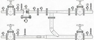
Design, purpose and principle of operation of the hydraulic arrow
The hydraulic arrow for heating consists of a bronze or steel body with two pipes for connecting to the boiler circuit (supply pipe + return pipe), as well as several pipes (usually 2) for connecting the heat consumer circuits. An automatic air vent is mounted in the upper part of the hydraulic separator through a ball valve or shut-off valve. at the bottom there is a drainage tap. A special mesh is often installed inside the housing of factory hydraulic arrows, which allows small air bubbles to be directed into the air vent.
Design of the Valtec VT model. VAR 00.
The hydraulic arrow for heating performs the following functions:
- Maintaining the hydraulic balance of the system. Turning on/off one of the circuits does not affect the hydraulic characteristics of the remaining circuits;
- Ensuring the safety of cast iron boiler heat exchangers. The use of a hydraulic arrow allows you to protect cast iron heat exchangers from sudden temperature changes (for example, during repair work, when the circulation pump is turned off, or when the boiler is turned on for the first time). As is known, a sharp change in coolant temperature negatively affects cast iron heat exchangers;
- Air vent. The hydraulic arrow for heating performs the functions of removing air from the heating system. To do this, in the upper part of the device there is a pipe for installing an automatic air vent;
- Filling or draining coolant. Most of both factory-made and self-made hydraulic switches are equipped with drain valves, through which it is possible to fill or drain coolant from the system;
- Cleaning the system from mechanical contaminants. The low flow rate of the coolant in the hydraulic separator makes it an ideal device for collecting various mechanical contaminants (scale, scale, rust, sand and other sludge). Solid particles circulating through the heating system gradually accumulate in the lower part of the device, after which they can be removed through the drain valve. Some models of hydraulic arrows can be additionally equipped with magnetic catchers that attract metal particles.
Diagram of a heating system using a hydraulic separator.
Advice! It is recommended to install the magnetic trap before the system is filled with coolant; otherwise, when installing the trap, it will be necessary to drain the water from the hydraulic separator.
The process of removing mechanical particles through the drain valve:
- Turn off the boiler and circulation pumps;
- After the coolant has cooled, shut off the section of the pipeline where the drain valve is located;
- We put a hose of a suitable diameter on the drain tap, or, if space allows, we substitute a bucket or any other container;
- Open the tap and drain the coolant until clean water comes out without any contaminants;
- Close the drain valve, and then open the blocked section of the pipeline;
- We subscribe the system and launch the equipment.
Where are the air release valves located?
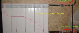
In any water heating system there are places where the installation of air vents is mandatory. If we talk about Mayevsky’s taps, then they need to be installed on all batteries in order to bleed off the collected air. The exact location is in the plug of the upper corner, distant from the point of connection of the supply line to the device. An air bubble forms there.
If the boiler is equipped with a built-in air vent, then there is no need to install it on the supply
The automatic air valve must be installed strictly vertically at the following points in the heating network:
- in the safety group of a boiler connected to a closed type system;
- on both underfloor heating collectors;
- if the highest point is a pipeline and not a radiator, then a float air vent cuts into it;
- into a buffer tank and an indirect heating boiler, if provided for by the design;
- on the heated towel rail coil;
- into the common distribution comb of a complex and branched system (to both collectors);
- to the hydraulic circuit separator (hydraulic arrow).
In addition to the indicated points, air vents are installed in problem areas of the heating network, where, due to difficult installation conditions, pipes form U-shaped loops turned upward. For example, a highway goes around a doorway or flight of stairs at the top, and then goes down again. In such compensators, air pockets form with a 100% probability, so an air vent is needed, preferably an automatic one.
When the highest point of the network is a pipe or compensator, a valve is mounted on it
Advice. Never cut the Mayevsky valve directly into the pipeline, since the bubbles will pass by it along with the coolant flow and the valve will be useless. For proper operation, a manual “bleeder” needs a chamber to collect air (the “automatic” has its own). Make a vertical pipe into the main line, which will serve as an air collector, and install a faucet on top.
If, when filling the heating network with water, you do not want to run between the radiators with a screwdriver, install automatic corner air vents instead of Mayevsky valves. This option is also suitable for residents of centrally heated apartments: air pockets often occur in cast iron radiators, and there is no way to remove them from there.
Another tip. To prevent the corner air vent flask from sticking out in plain sight and clinging to the curtains, take a mini-model of the valve built into the radiator cap.
Why should you use a hydraulic boom?
Section of the heating system with a hydraulic arrow.
From a different angle.
In heating systems where there are two or more heating circuits (radiators, water-heated baseboards, heated floors, hot water supply), as a rule, the circuits are connected to each other by a common manifold. At the same time, the presence of a common collector can lead to the following problems:
- The circulation pumps of each circuit influence each other (especially if the pumps differ in power). To overcome the effects of a more powerful pump, the low-power pump must operate at its limit, consuming more electricity than required under “normal” conditions. At the same time, working at the limit of their capabilities, pumps fail earlier. In addition, under such conditions the pump cannot always provide the required performance;
- Even if the circulation pump of one of the boilers was turned off, its radiators will still heat up (under the influence of the other pumps, coolant circulation in the turned off circuit will continue);
- Difficulties in calculating pump power for both the boiler and heating circuits. The boiler pump power should be selected taking into account the total power of the heat consumer pumps.
All of the above problems can be solved by a hydraulic arrow.
Side view of the arrow.
Note! In a hydraulic separator, the speed of movement of the coolant decreases sharply (by about 9 times), this is due to the fact that upon entering the separator, the diameter of the flow increases several times (usually 3 times). Thanks to this, pressure drops in the system are eliminated.
Separator Specifications
A grain separator can operate autonomously (as a stand-alone equipment) or be included in a common factory production line (much more often). The productivity of such a unit allows it to process a lot of products, and in this case it is beneficial to combine it with other technical equipment in production.
Depending on the quality of the grain mixture that must be processed in the separator, you can change its operating mode. The operating mode is regulated by changing the angle of inclination of the sieve devices. Thanks to this adjustment, the equipment is used for primary cleaning (as in elevators), preliminary and in-depth. Its productivity depends on the variety and quality of the grain crop being cleaned, and the cleaning efficiency reaches 78-85%. The price of a grain cleaning separator may vary depending on the technical characteristics of the equipment and its technological perfection.
Types of grain cleaning separators
Air sieve separators separate the grain mixture by size and aerodynamic characteristics.
Its inclined gratings perform reciprocating movements. At the entrance to the separator, the grain is processed by an air flow and then fed to the grates. Moving along the grates, the product is divided into fractions and returned to the air flow for final cleaning. This device includes a magnetic separator. The grain separator separates dust, grain shells, and various impurities, since their aerodynamic characteristics differ from the parameters of the grain. Calibration of the grain mixture occurs in a channel located vertically. Thus, the moving layer of grain is separated by air flow.
Air-sieve separators separate raw materials by width and thickness, as well as by the speed of movement of particles in the grain mass.
Completed projects
Construction of elevators, grain complexes. Production of elevator equipment.
Separator layout diagrams
When a sieve and pneumatic separator are combined in one machine, operating efficiency is improved; one mechanism distributes the grain flow across the width of the pneumatic channels and sieves. The layout of air-lattice grain separators is different. A common scheme is in which a pneumatic separator is mounted in front of the sieve mill: the efficiency of the unit increases after removing light impurities from the grain mass.
In some schemes, a pneumatic separator is installed after the sieve mill. They are used in low-capacity units, as well as for pre-cleaning grain, where flat sieves with large holes are installed.
Technological schemes for double cleaning of grain with an air flow are also used: before and after the sieve.
Rotary grain separator
As we have already noted, the grain mixture is separated by a separator on sieves according to the thickness and width of the components, as well as according to their aerodynamic properties. The division is performed sequentially. First, the grain is cleaned of light impurities (dust, chaff) by air in pneumatic separators at the outlet of the bunker, and then sifted on flat sieves, where large and small impurities are removed. The sorted grain is additionally blown by an ascending air flow in the aspiration channel at the outlet of the separator.
Special differences between drum separators are lower dynamic loads on the components compared to separators with flat sieves, low speed, and absence of noise and vibration. According to the operating principle, drum-type separators do not differ significantly; only the design of some components is different. Such separators can be used for pre-cleaning of grain and its primary and secondary purification. The separators are equipped with aspiration channels, which allows light impurities to be separated from the grain mass at the entrance to the machine.
Vibrating grain separators
One of the ways to intensify the grain separation process is to use an additional force field during vibration and rotational movements of the working bodies. This method is used in vibration-type grain separators. The working body of the separating unit is a vertical cylindrical sieve, rotating around a vertical axis with oscillatory movements. Grain material is fed onto the inner surface of the sieve. Thanks to the action of centrifugal forces, particles smaller than the size of the sieve openings pass them, and larger ones gradually fall down, where they are removed by a screw or other transport devices. In a vertical cylindrical sieve, the field of centrifugal inertial forces is distributed evenly over the entire surface, and a circular shift of the grain layer does not occur during its steady-state movement. To prevent the material from “sticking” to the sieve and to allow relative movement of the grain layer by its surface, a mechanism for vibration of the sieve cylinder in the vertical plane was additionally used.
Separator efficiency
Modern technologies in equipment production allow business owners to choose the best units for their plant. But new equipment used in elevators and feed mills does not always meet the requirements of production technology. Sometimes it has excessive energy and metal consumption. Managers of enterprises and holdings are concerned about increasing the efficiency of using machines and their rational purchase. Note that drum-vibration and rotary separators have significantly higher values of specific metal and energy consumption, which is explained by the peculiarities of their operation and structure. The analysis shows that flat screen separators dominate over other comparable conditions.
Taking into account practical experience, we note that with a drum-vibration separator, a reduction in the amount of impurities in one pass through the separator is achieved by more than 3%.
As a conclusion, we can say that the use of drum-vibrating separators will be appropriate for cleaning sunflower seeds. Separators with flat sieves can be called universal. A drum separator is more suitable for cleaning corn grains.
Where can I buy
Among the domestic enterprises engaged in the production of ready-made hydroshooters is the Novosibirsk company TMK Gulfstream.
Hydraulic distributors are produced here from high-carbon steel with a thickness of 3 mm.
Simple devices with 4 pipes cost from 3.1 thousand rubles. (up to 50 kW). A similar device up to 100 kW will cost almost 4 thousand rubles.
There are models combined with a collector. Such a kit for three circuits will cost 6.8 thousand rubles. Five-circuit – 9.3 thousand rubles. Among the products there is also powerful boiler equipment. For example, a DN100 switch, designed to operate up to 500 kW, will cost 25 thousand rubles.
You can contact the organization by phone +7 913-953-16-80.
Many other manufacturers also produce hydraulic distribution equipment (only the prices are much higher):
- Italian company Immergas;
- Ariston;
- Meibes and others.