All well-known manufacturers of water heating and heating equipment take their reputation in the market and in the consumer environment very seriously, therefore they do everything to ensure that accidents and accidents when using their products are excluded. All boilers that heat water under pressure of more than 1 bar are tested on special stands and installations. But even in this case, manufacturing companies remind in the instructions that it is mandatory to install a safety valve for the boiler. This is the only way to ensure the required level of security.
What is the purpose of a bypass valve in a pipeline?
During operation of heating or water heating systems, the volume of the working medium may change.
An increase or decrease in coolant pressure negatively affects the performance of the heating circuit: it can lead to uneven heating, airing of system components, and breakdowns. Changes in the pressure of the working environment also affect comfort: the temperature in the rooms changes uncontrollably, and the pipes begin to hum and vibrate . To prevent this from happening, it is important to maintain a pressure balance in the pipeline
It is not difficult to constantly monitor the pressure, bleed or add coolant manually, but it is better to entrust this routine work to automation.
There are several types of control valves that cope with this task better than a person.
The bypass, or overflow, valve allows you to stabilize the pressure in the pipeline by redirecting the working fluid through an additional branch of the pipeline, called a bypass.
Regulation does not occur by one-time or periodic bleeding of excess coolant, but in portions, due to which the pressure of the liquid or gas is constantly maintained at the same level.
The device can and should be equipped with pipelines of any complexity, but most of all they need pressure adjustment:
multi-circuit heating systems - if one of the circuits is turned off, coolant consumption decreases and pressure increases, which can cause pipeline breaks, overload the pump and heat-generating device - to avoid this, you need to reduce the pressure and maintain it at the required level; heating systems equipped with thermostats and hot water supply systems - when setting the temperature, the volume of coolant consumed changes, and it is necessary to quickly restore the pressure balance in the circuit; water supply systems equipped with storage-type water heaters - in the boiler and pipeline the water is under high pressure, and since the volume of supplied liquid changes jerkily due to constant adjustment and frequent turning on and off of water, it is especially important to regulate the pressure of the working medium so that an accident does not occur and The water heater is broken.
Purpose of the gas valve
PSK is a safety valve element responsible for the safety of the gas pipeline and gas equipment connected to it. During operation, the valve is in a closed position, therefore it is classified as a closed pipe fitting.
Such devices are installed not only on gas pipelines, they are an integral part of other communications - water supply, heating networks. Everywhere they perform the same function - they stabilize the pressure in the network, provide the operating parameters necessary for the proper functioning of the system.
The valve serves to relieve excess gas if pressure parameters become critical. Fuel that creates an imbalance in the system is discharged into an auxiliary pipeline or discharged into the atmosphere
The pressure surge is usually short-lived and depends on a number of factors.
Reasons that can cause excess pressure in the system:
- breakdown of connected gas equipment - double-circuit boiler, instantaneous water heater or capacitive boiler, shut-off valves;
- use of fuel of inappropriate composition;
- change in temperature indicators in the pipeline;
- failure in the thermal-mechanical circuit.
The installation location of the gas safety valve is standard, depending on the efficiency of the application: either in the pressure regulator, or immediately behind it. After automatic operation of the valve, it returns to its operating – closed state.
In a gas network, the valve is a separate device or integrated into the pressure regulator. It is triggered if the operating gas pressure exceeds the nominal level by 15%
What are the consequences of the absence of a PSK on the network? The most common consequences are mechanical destruction of the pipeline or breakdown of connected equipment, which can cause a gas leak.
There is also a possibility of an explosion, so it is necessary to constantly monitor the serviceability of the device, carry out timely maintenance and replace failed elements
Along with relief devices, gas safety shut-off valves are also used, with the help of which the fuel supply is shut off. This happens automatically. The shut-off valve element is installed on the pipeline, in the gap between the filter and the pressure regulator.
The operating limit of the SPD is indicated in the technical data sheet of the device. The upper critical parameter is usually equal to the formula: slave. pressure +25%.
Differences in Designs
The design of different safety valves may vary. Thus, most of the fittings are produced with one saddle. You can also find designs in which two saddles (and two rods with springs) are installed side by side.
Based on the ratio of the lifting height of the locking element to its diameter, the following are distinguished:
- small lift: up to 1/20;
- medium rise: up to 1/4;
- full lift: over 1/4.
The higher the degree of lift, the faster the device operates. Low-lift models are used for liquids, where it is not necessary to discharge large volumes to reduce the pressure to normal. In them, the lifting height is proportional to the pressure of the medium. Full lift is also called two-position. They have two positions: “Open” and “Closed” and are intended for:
- high pressure liquid systems;
- gases
This design allows you to quickly discharge a significant volume of gas or liquid and is used in particularly critical installations and technological complexes.
The most serious design differences are observed in the methods of applying loading force to the closure organ.
Spring valves
Most common in household systems - water heating, plumbing, heating. The spool is pressed against the seat by the force of a compressed spring. By changing the degree of pre-compression of the spring with an adjusting screw, it can be adjusted to different limit values. Many models are equipped with a lever for forced manual opening of the shutter in order to check operation from time to time. For devices operating in hazardous and hazardous environments, manual control purge is not provided. Springs, seats and chambers of devices operating in aggressive liquids and gases are coated with special anti-corrosion coatings.
The rod passing through the body is sealed with a double seal made of particularly resistant materials (special grades of rubber, fluoroplastic), which under normal conditions prevents the penetration of aggressive substances into the room.
Lever-weight valves
Such structures use the force of gravity to counteract the force of pressure. They can only be mounted in a position strictly defined by the manufacturer relative to the horizon and are not approved for use on vehicles and other moving objects. The weight of the load is transmitted through the lever to the spool rod, balancing it as long as the pressure in the pipeline is below the threshold.
To get rid of these effects, double-seat valves are used, each of which is small in size and weight. Adjustment of such devices is carried out by adding or removing part of the load placed on the lever. They are characterized by stable operating parameters and the absence of the effect of aging of springs, which reduces their elasticity.
Magnetic spring valves
Modern designs are classified as indirect-acting products. The shut-off element is actuated by a solenoid. In the normal position, the electromagnet presses it to the seat, and when the maximum pressure is reached, the automatic control switches off the voltage on the inductor. The pressure of the medium presses the spool and the valve opens.
In another design, pressing is carried out by a powerful spring, and when a threshold pressure value is reached, the control command turns on the solenoid, and it lifts the valve.
There is a design in which the solenoid both presses the spool and presses it under the influence of oppositely applied voltage. In the event of a power failure, the device continues to operate as a normal spring device.
The main advantage of magnetic devices is that there is no need for physical access to the valve to set the threshold value. The threshold can be changed in the settings of the control program depending on the current situation or the features of a given stage of the technological process.
Such designs are significantly more expensive than their mechanical counterparts, but they pay for themselves many times over in complex industrial installations with a large number of parameters and elements influencing each other.
Recommendations for selection and installation
- when the plate is lifted, the force of the spring increases due to its compression - this should be taken into account when adjusting;
- since the spring constantly presses on the valve, it can stick to the seat (choose models with a handle for manually opening the valve for control).
Lever-load valves do not suffer from sticking (the load lies on the support), but due to their large dimensions and high cost, today they are used only on main pipelines.
It is not necessary to purchase an adjustable valve. Products with a fixed setting are much cheaper.
An important characteristic is the relative difference between the pressure at the beginning of the shutter movement and when it is fully opened. It should be:
- at a nominal pressure in the pipeline of less than 2.5 atm: 15%;
- at pressure above 2.5 atm: 10%.
Thus, a vessel with higher pressure requires a faster response valve.
The valve outlet is usually connected to the sewer, but not directly (otherwise the sewer will be under pressure), but through a visible break in the stream: from the valve, the coolant flows into a funnel, sink or pit, and from there it flows by gravity into the sewer.
In the operation of centralized heat supply networks, the elevator unit of the heating system is actively used. Read about the purpose of the elevator unit and see its connection diagrams.
What functions does a bypass perform in a heating system and in what cases is its installation necessary? Read in this topic.
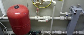
Installing the device into the system
Schematic illustration of a boiler piping using a pressure relief valve.
Some boilers, usually wall-mounted, already have emergency valves installed by the manufacturer. If it is not there, a safety valve is installed on the boiler supply line in compliance with all the requirements described below:
location on the supply pipeline – 200-300 mm from the boiler; in systems with natural circulation, emergency valves are installed at the highest point; For tightness, it is important to seal the threads of the fittings with tow or silicone (but not with FUM tape, which cannot withstand temperatures above 70-80 degrees without deformation); the valve itself must be positioned vertically (with the plastic handle up) so that an air gap is maintained under the spool; with this installation, the mechanism has the longest service life; It is advisable to install a pressure gauge in front of the valve (if it is not part of the safety group); there should be no check valves, gate valves or taps on the line between the boiler heat exchanger and the discharge valves; To prevent the coolant from dripping onto the floor when the valve ruptures, it is necessary to put a drain pipe leading to the sewer or return line onto the valve; when venting to the sewer, it is important to make a connection that involves breaking the stream (for example, through a funnel and a water seal). Thus, the system will work even if the drainage pipeline is clogged and will rid the boiler room of coolant odors.
Adjusting the mechanism for proper operation
The safety valve is adjusted after completion of installation work and complete flushing of the system. Spring devices can be adjusted by rotating the adjusting knob (colored plastic cap), the rotation compresses or decompresses the spring that puts pressure on the spool. In lever-load trucks, this is done by hanging a load on the lever.
It is necessary to set the set pressure, full opening and closing:
- The setting pressure should be set slightly higher than the maximum operating pressure of the boiler.
- The full opening pressure should not exceed the maximum permissible standards of the most vulnerable element of the system, usually the boiler heat exchanger, designed for 3 or 2 bar, and in some Russian models even 1.5 bar.
- The valve closing pressure must be set slightly higher than the minimum allowable for system operation.
Breakdowns, causes, elimination
In principle, the safety valve for a water heater has only two failures: water either often flows from it or does not flow at all.
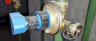
First of all, it must be said that bleeding of water when heating is the norm. This is how the system is supposed to work. Water may also be released when the boiler is turned off, if the pressure in the cold water supply pipes is higher than the valve response limit. For example, the valve is 6 bar, and the water supply is 7 bar. Until the pressure drops, the water will be released. If this situation repeats often, it is necessary to install a reducer, and it is best to use water in an apartment or house, but there are compact models of reducers that can be installed at the entrance to the boiler.
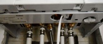
Boiler piping with safety valve and reducer
How to check the serviceability of the valve? If there is an emergency reset lever, this is easy to do. With the boiler turned off, you need to lift the lever several times to release excess pressure. After this, the dripping stops and does not resume until heating begins.
If water continues to drain, the spring may be clogged. If the model is serviceable, the device is disassembled, cleaned, and then put back in place. If the model is not collapsible, you just need to buy a new valve and install it.
This is what the reducer looks like - to stabilize the pressure on the boiler
Constantly dripping water is unpleasant and hurts your wallet, but not dangerous. It is much worse if, when heating the water, you never see water in the pipe. The reason is that the valve is clogged or the outlet fitting is clogged. Check both options. If it doesn’t help, change the valve.
Safety valve in the heating system: principle of operation and installation
Who first invented the safety valve? History is silent about this. Only one thing is known - this simple device prevented many accidents and saved hundreds, if not thousands of human lives. A mandatory element - a safety valve in the heating system protects the circuit and boiler from mechanical destruction by excess pressure. It is considered a direct-acting mechanism, because it works directly with the working medium, discharging excess liquid, steam, or a mixture of steam and liquid.
Heating system protection - safety valve
All heating circuits and any boiler equipment, regardless of installation location, are sources of increased danger. They can be considered as a vessel under pressure. The heating system includes a boiler, the coolant is heated in it, and under certain abnormal conditions it can destroy the equipment. You can read about boiler heating at home here.
To protect heating systems, a heating safety valve is used, a simple yet effective device.
Principle of operation
It is known that the simpler the design of the device, the more reliable it is. The valve consists of a body and the main working element - a steel spring. The elasticity of the spring, which is regulated by a special screw, determines the amount of pressure at which the membrane, under the pressure of the spring and the internal pressure of the circuit on the other side, will open the passage to the outside. As soon as the pressure in the heating system returns to normal, the spring will return the membrane to its original position.
Selection and installation of a safety valve in the circuit
In private houses and small central boiler houses, spring relief safety valves are installed. In heating circuits with pipe diameters over 200 mm, so-called lever-load valves are installed. Correct selection of a safety valve for a heating system takes into account its inertia, which for systems with pressure up to 0.25 MPa is 15%, and above 0.25 MPa - 10%. This means that for high operating pressures, the valve must operate faster.
When selecting a valve, it is important to choose the correct diameter, which should be equal to the diameter of the supply pipe. The ideally selected safety valve for heating boilers must take into account the technical characteristics of the membrane expansion tank
The valve must operate immediately if the expansion tank is no longer able to compensate for the increase in coolant volume during heating. According to existing rules, a safety valve for a heating system is installed only at the outlet pipe of the heating boiler. A pressure gauge is installed parallel to the valve to monitor the condition of the circuit.
When installing valves, be sure to consider the following:
- there should be no installed devices between the boiler and the valve;
- install a drain pipe to remove excess water into the sewer or return line;
- in a closed system the valve is installed at the highest point.
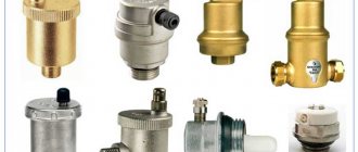
Why are valves on batteries needed?
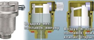
Valves are also installed on radiators and circuit batteries, but their main function is to remove air from the system.
The installed valve for the heating radiator can be manual or automatic. The manual valve is opened and closed manually using a key and screwdriver.
The automatic valve on the heating radiator does not require human intervention. It removes air perfectly, but its main drawback is its sensitivity to blockages due to contamination of the coolant. To remove dissolved air from the coolant and clean it of dirt and sludge, it is recommended to install air separators.
Purpose
The safety valve is designed to protect the heating system from negative consequences that can occur in a situation when the coolant overheats.
p, blockquote 3,0,0,0,0 —>
Pressure drops are a typical phenomenon for boilers and occur for a number of reasons:
p, blockquote 4,0,0,0,0 —>
- the amount of coolant goes beyond the norm, and, ultimately, the automation fails;
- a sharp increase in temperature.
If a safety valve is not installed in the heating system, the consequences of overheating will be unpleasant:
p, blockquote 5,0,0,0,0 —>
- in those areas where pipeline elements are connected, leaks may form;
- Defects may occur on fittings and pipes made of polymer;
- The water jacket of the boiler may also explode, which can result in a short circuit of electrical equipment in the boiler room.
Safety relief valve selection criteria
Clamping mechanism
Lever-load safety valves are designed for heavy loads and a pipe diameter of at least 200 mm, therefore they are used in industrial heating systems.
For individual heating of a private house, it is better to purchase a device with a spring mechanism; this is a standard, reliable and frequently used type of relief valve.
Lifting height
Pressure relief valves have different valve lift heights:
- Low lift. The height of the shutter in low-lift valves does not exceed 1/20 of the seat diameter. They have a relatively low throughput and a simple design. Used in lines with liquid coolant. As a rule, low-lift safety valves are sufficient for a heating system with a water circuit with a power of up to 40-43 kW. To prevent an accident in such systems, it is necessary to discharge a small volume of coolant.
- Full lift. The height of the valve in full-lift valves is greater than or equal to the diameter of the seat. As a rule, these are lever-load mechanisms, more expensive and complex in design. Full-lift valves have a high capacity and can be installed on lines in which gases, steam or compressed air circulate.
Full lift model PN 16.
Mechanism response speed
Based on response speed, safety valves are divided into proportional and on-off.
In heating systems of a private home, it is better to use proportional valves; again, they are sufficient for most systems. The shutter cover of such devices opens gradually, in proportion to the increase in pressure in the line, and accordingly, the volume of coolant discharged increases proportionally. Such valves do not self-oscillate, they maintain the correct pressure level and are cheaper.
Two-position safety valves are distinguished by instantaneous detonation and full opening of the valve. This mechanism allows you to quickly release large volumes of coolant, but creates the risk of water hammer: due to the rapid release of a large amount of coolant liquid, the pressure in the line significantly decreases, after which the valve closes sharply. Therefore, it is recommended to install two-position safety valves on lines with a compressible medium (air, gas, steam).
Diameter
The diameter of the pressure relief valve in the heating system should not be less than the connector of the supply pipe. Otherwise, the constant hydraulic pressure will interfere with the operation of the mechanism.
Manufacturer
Since safety valves have a fairly simple design, and modern models are in most cases made of brass using the same technology, there are no critical differences between valves from different manufacturers.
Types of emergency valves
Various types of emergency devices for boilers are produced, which differ
:
- According to the plate pressing mechanism:
- spring;
- lever-load.
- According to the lifting height of the locking mechanism:
- low-lift (the lifting height of the plate does not exceed 5% of the diameter of the seat part, the devices are intended only for systems filled with liquid);
- full-lift (the shutter rises high, allowing a large volume of medium to be discharged; the device is suitable for systems designed to transport liquid and steam).
- By response speed:
- proportional (the valve opens smoothly, in accordance with the increase in pressure in the pipeline, closing does not cause water hammer);
- two-position (they open sharply and are capable of releasing a large volume of medium; due to abrupt closing they provoke a water hammer).
Spring type valves
A spring safety valve for heating is the most common option, designed for operation as part of autonomous heating systems. It has a simple design and reliability. The spool rod is pressed using a spring, the pressing force depends on the degree of its compression. A regulating mechanism is provided to adjust the response parameters of the emergency device.
Spring type safety valve
Lever-load type valves
The lever-load pressure relief valve is intended for use on pipelines with a diameter of at least 200 mm and is rarely used for heating systems in private homes, where the heat source is a boiler. In such devices, a weight is used to reinforce the rod. To set the pressure level at which the valve should operate, adjustment is made by changing the mass of the load on the device lever.
Lever type valve
Design and principle of operation of the valve
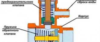
The design of the valve is extremely simple. The body is made of high-quality plumbing brass using hot stamping technology from two cast parts in a semi-solid state. The general design of the safety valve is shown in the figure:
The main working element of the valve is the spring. Its elasticity determines the force of pressure that should act on the membrane that closes the passage to the outside. The latter in its normal position is in a seat with a seal, pressed by a spring. The upper stop for the spring is a metal washer mounted on a rod, the end of which is screwed to a plastic handle. It is used to adjust the valve. The membrane and sealing elements are made of polymer materials, the spring is made of steel.
This whole simple mechanism works like this. In normal (standby) mode, as long as the coolant parameters are within the specified limits, the membrane closes the entrance to the inner chamber. As soon as a situation close to an emergency arises and the pressure in the heating system of a private house increases, the steam-water mixture begins to prop up the membrane. At a certain moment, the pressure force of the coolant overcomes the elasticity of the spring, opens the membrane, enters the chamber, and from it out through the side hole.
When some water leaves the system, the pressure will drop so much that it will not be able to resist the spring and the membrane will close the passage again. It happens that the mechanism operates cyclically, especially if the heating unit is operating at its limit and the coolant temperature is close to the maximum (90-95 ºС). In practice, when the burst valve for a boiler is triggered very often, it loses its tightness and begins to leak.
If you find fresh traces of leaks from the safety mechanism, then this is a clear sign that the heat generator is operating in extreme mode or that there is a malfunction in the heating system, for example, in the expansion tank.
Final tips
If you are keenly interested in the safety of the boiler room and the reliable operation of heating equipment, then we recommend that you carefully study the range when purchasing fittings. The fact is that new useful products are appearing on the market that cannot be reviewed within the scope of this article, but they may be useful to you.
Operating moment. Monitor the condition of safety valves in order to detect activation in time and understand the reasons. Direct the heat release devices into the sewer funnel with a burst of stream - an unexpected splash of water in the boiler room and wet footprints will make it clear that an emergency situation has occurred.
Safety valve selection
The diameter of the inlet pipe of the selected safety valve must be greater than or equal to the diameter of the pipe obtained as a result of the calculation.
In addition to the compliance of the pipe diameter with the calculated value, it is recommended to check the safety valve for the release of the calculated increase in water volume as a result of an emergency situation. It should be taken into account that the greater the pressure difference between the opening pressure of the safety valve and the pressure in the discharge line, the greater the volume of water will come out through the valve.
When selecting a safety valve, you should also keep in mind that full opening of the valve is achieved when the pressure in the system exceeds the response pressure by 10%, and complete closure is achieved when the pressure in the system decreases below the response pressure by 20%. In this regard, it can be recommended to choose safety valves with an operating pressure 20 - 30% higher than the operating pressure of the system.
Is it possible to install other valves?
Sometimes, instead of a special safety valve for a boiler, a blast valve is installed, which is intended for the emergency release of heating water. Although their functions are similar, the main mode of operation is fundamentally different. The demolition device should only be used in emergency situations. It is designed for volley discharge of a large volume of liquid. It is not suitable for constantly bleeding small portions of water. Accordingly, it will not work correctly.
Another case is to install only a check valve. It will not allow water to drain when the pressure in the water supply decreases, but it will not save you from increasing pressure in the boiler. So this option doesn't work either.
Three-way
There is practice to achieve a certain coolant temperature in various branches and CO circuits by mixing or separating coolant flows. Three-way valve on a heating system
plays the role of a device that regulates the temperature of the working fluid after the heat generator.
The design of the mixing fittings is simple: there are three holes in the device body, two inlets and one outlet. Separating type devices have one input and two outputs.
The main control device of this element is a thermal head, inside of which there is a reservoir with liquid (bellows). When the remote sensor heats up, the liquid in it expands and enters the bellows. The volume of this reservoir increases and affects the valve stem, which opens or closes the inlets for mixing or separating flows. In separating types of this CO element, the same principle is used, but the rod does not open a passage for flows, but divides one flow into two.
It is not only the thermostatic head that can control the device. Manually controlled devices are quite popular. The depth of pressing of the rod is determined by the rotation of the control handle. Today, these devices with electric and servo drives are widely represented on the climate control equipment market.
Which valve to choose?
The variety of models presented for sale, despite the similarity in design, is very large. Therefore, it is difficult to give any specific recommendations. We can only list some criteria that are worth paying special attention to.
- As already mentioned, the valve must have an inlet connection size (DN) that is the same as the pipe on which it will be installed. No transitions to more or less!
The nominal diameter is indicated on the valve body.
- The second most important parameter is the valve activation pressure. As already noted, for most autonomous systems the optimal threshold is a level of three atmospheres. However, there are exceptions - it is better to discuss this with specialists when designing heating.
By the way, some companies practice color marking of their valves - according to the color of the plastic release handle. For example, red – 3.0 bar, black – 1.5 bar, yellow – 6.0 bar.
Valves of different response ratings - the manufacturer has highlighted them in different colors
However, you cannot completely rely on such signs - this is not some generally accepted standard. It is quite possible to see valves with a blue head, and with ratings of six, eight, and ten bar. So always check what exactly is indicated on the device.
- It has already been said above that preference should be given to devices in brass cases.
- Of course, you should not dig for safety valves of completely unknown origin. Even if the price seems very tempting. Never forget that in this case we are also talking about your personal safety.
The stores have plenty of high-quality products from well-known brands - Valtex, BAXI, Ariston, Beretta, Danfoss, Ferroli, Vaillant, Watts and others. It would be useful to read information about the products in advance on the official websites of the companies.
Of course, the purchase should be made in a specialized store. Do not hesitate to request documents that can confirm the originality of the selected product.
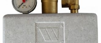
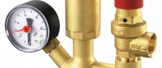
- Many argue that from the point of view of both convenience and overall cost, it is much more profitable to purchase a ready-made “security group”.
An example of a “safety group” kit is a cast iron manifold, safety valve, air vent and pressure gauge, with all the necessary connecting fittings.
In conclusion, we attach a video in which the author shares his experience in identifying and eliminating problems with the safety valve.
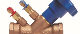
Types of balancing valve
The balancing valve helps to achieve hydraulic balance during the preparation of the heating system. There are two types of balancing element:
A statistical balancing element is needed to create a constant resistance built into the system. All settings for such a balancing device must be elements that can affect losses through all others.
Dynamic balancing devices serve as flow limiters, regulating all losses. The balancing elements are adjusted to a certain level of flow rates and maintained within specified specific limits. As the pressure in front of the valve increases, it opens slightly so that the pressure through the balancing element becomes higher. This allows you to maintain and control consumption within the desired limits. The outlet pressure for a dynamic balancing valve must be below a certain level to ensure proper operation (the resistance at the outermost valve cannot be near 0, unlike a static balancing valve).
Balancing elements are of manual type and automatic regulating type. Even the highest quality calculation requires settings, including balancing devices. Pressure and temperature adjustment is carried out using control valves
The balancing device, like other elements, is very important and has its own tasks. Adjustment in the upper pressure threshold is an important point if there is a balancing control device
A valve can also perform a balancing role. But there are differences from the balancing element. It performs a subtle regulatory task.
The balancing control element distributes heat precisely. Balancing elements have a functional range:
- pressure support;
- flow limitation;
- blocking the pipeline.
The balancing element automatically keeps the flow in balance in the range of 0-100%. For the automatic balancing device, it does not matter whether the supply is warm or cold.
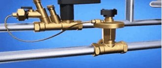
Rice. 2 Bypass control valve
The balancing element operates silently. The balancing valve setting is automatic, no complicated pipeline calculations are used. Automatic balancing devices allow you to divide the pipeline zone into parts independent from each other. Apart from zone balancing, the balancing valve does not require static adjustment.
Safety valves and their description: features of pressure regulation and settings
Sometimes unpleasant circumstances arise when the heating system malfunctions and the pressure begins to fluctuate. If the pressure is not regulated, the consequences can be dangerous. To prevent this from happening, the heating system and hot water supply system should be equipped with safety valves. What they are and how they work – we will tell you in this material.
Types of safety valves
In a heating system, a safety valve performs a protective function to prevent high pressure. This is especially important for steam boilers.
Blood pressure rises most often due to the following reasons:
- failure of automatic pressure control systems;
- a sharp increase in ambient temperature and the appearance of steam.
Safety products are mainly of two types:
- spring;
- lever-load.
In lever-load structures, the action of pressure on the spool is counteracted by a load, its force is transmitted through the lever to the rod. It moves along the length of the lever, and in this way you can adjust the force of pressure of the spool against the seat. Then it opens when the working medium begins to press on the lower part of the spool with a force greater than the force of the lever pressure and the water leaves through the pipe.
And spring safety units operate using an electromagnetic drive . A spring exerts pressure on the spool rod, and adjustment occurs by changing the degree of compression of the spring.
Small heating systems are best combined with spring products; their advantages in this case are as follows:
- compactness;
- the setting can only be changed when using the tools;
- the spool rod may have different positions;
- Possibility of combination with other products.
According to the principle of operation, safety valves are divided into the following:
- direct action devices;
- indirect;
- two-position.
A direct-acting safety valve can only open under pressure from the working medium, while an indirect safety valve can open only under the influence of a pressure source.
And according to the type of lifting the constipation, the devices are:
- low-lift;
- medium-lift;
- full lift.
Manufacturing materials
Safety products can be made from the following materials:
- brass;
- steel;
- Cink Steel;
- stainless steel
The safety brass coupling valve for the boiler is threaded on both sides and has a gasket on the inlet side. The mechanism is spring-loaded. External pressure can increase the blockage. After assembling the structure, it is pressurized, so this type of valve is very reliable and affordable.
can also to protect against backflow pressure.
Features of three-way valves
The purpose and operating principle of three-way safety valves is somewhat different from other options, and here are their key differences:
- use is permissible in low-temperature heating systems for media cooling;
- it is possible to adjust the product manually or using an electric drive;
- the presence of one inlet and two outlets;
- To regulate the flow, there is a special valve in the form of a ball or rod that directs it to the desired hole.
Such valves are most often used in heating systems that include “warm floors”. In this way, the water for heating the floors will be much cooler than the water in the radiator.
For the manufacture of three-way safety valves the following is used:
Brass designs are most common when installing home heating systems, while steel and cast iron are more common in larger industrial installations.
It is also worth paying attention to the explosion safety valve, which can prevent the explosion of flammable gases or coal dust. They are made in such a way that if the substance explodes, only the membrane of the structure is damaged, and the pipeline remains unharmed.
This type of product operates automatically. Depending on the pressure, they are distinguished into several types:
- with pressure up to 2 kPa;
- up to 40 kPa;
- 150 kPa inclusive.
How to choose the right safety valve
When choosing a safety valve, there are a huge number of factors to consider. In particular, be sure to take the ambient operating pressure into account. If this pressure is higher than normal, then you need to choose a 2 bar product that can withstand such operating conditions of the product. In addition, you can choose an option with the ability to adjust the pressure so that you can adjust the required mode and find out the exact parameters, in particular, the nominal diameter.
There are a number of standards regarding the performance of calculations; you can also find special calculation programs on the Internet. You can do without calculations and take a design with a diameter no less than the diameter of the outlet pipe of your boiler, but such a calculation will not be accurate and cannot guarantee a high level of safety and performance.
In general, in order to choose the right product, you should consider the following parameters:
- decide on the type of product;
- with a size so that the pressure in the system does not exceed the permissible limits;
- It is better to choose spring-type products for your home;
- open devices are suitable only if the water goes into the atmosphere, and closed ones - if into the outlet pipeline;
- after calculations, you can determine whether a low-lift valve or a full-lift valve is suitable;
- calculate your budget.
Safety valve prices vary depending on the material and other features. For example, an Italian-made membrane structure can be purchased for about 4 USD , and a brass one - starting from 12 USD. There are also some valve models whose cost exceeds $100.
Safety valve installation features
When installing the valve, you must strictly follow all the rules that are listed in the regulatory documentation of the product. Also, the installation must be carried out taking into account the power and operating pressure.
But the key installation principles are:
- carry out preliminary calculations of structural elements;
- Installation is carried out on the supply pipeline next to the boiler;
- It is recommended to place a pressure gauge next to the valve;
- when using a spring design, the spring axis must be vertical and placed above the body;
- The lever of a lever-and-weight valve must be horizontal above the valve;
- in a hot water system, the valve must be installed at the highest point of the water heater at its outlet;
- diameters cannot be narrowed if the valve dimensions do not match the pipeline diameter and for other reasons;
- the connecting pipe should not be too long;
- after connecting to the pipeline, the pipes must be taken to a safe place;
- the valves are adjusted to 20 percent more than the operating pressure of the heating system;
- the check must be performed by forced opening.
We also must not forget that it is necessary to regulate and check the pressure at least once a year before the heating season.
How to set a safety valve
The valve must be adjusted at the installation site after completion of installation work and after the system has been flushed. Set the setting pressure, check the opening and closing pressure of the product.
The settings should be set slightly above the maximum operating pressure, which is permissible during normal operation of the structure. And the full opening pressure should not be higher than the minimum level of the weakest element of the system. The closing pressure must exceed the minimum permissible value.
The pressure in the spring structure must be adjusted by rotating a special screw that compresses the spring, and the lever structure is adjusted using the required mass of the load.
Peripheral secondary part
A check valve is an element of the heating system, consisting of a plastic or metal base, which performs the function of completely shutting off the coolant supply. This happens when the flow begins to move in the opposite direction. The metal disk is attached to a spring, which is under pressure when the flow moves in one direction, and when it moves in the opposite direction, the spring is activated to block the passage in the pipe. The valve device has not only a disk and a spring, but also a sealing gasket. This component helps keep the disc in place tightly. Because of this, there is practically no possibility of pipe leakage. Butterfly valves are widely used in domestic heating systems.
Let's look at the principle of operation and an example of when check valves are needed and when they are not. In the operating mode of circuits where there is circulation, the presence of a valve is not necessary. For example, if you look at a classic boiler room, where there are three parallel circuits. This can be a radiator circuit with a pump, a heated floor circuit with its own pump, and a boiler loading circuit. Often such schemes are used when working with floor-standing boilers, which are called pump priority schemes.
Pumping priorities are the determination of alternating operation of pumps. For example, the use of check valves occurs when only one pump remains in operation.
The installation of valves is completely unnecessary if there is a hydraulic arrow on the diagram. This allows, during pressure drops in certain pumps, to get rid of this problem without using check valves. The hydraulic arrow indicates the closing section, which works to restore pressure in one of the pumps.
The presence of a floor-standing boiler in the circuit also makes it possible not to install check valves for heating. This occurs due to its barrel, which bridges a certain place from the drop, which is considered to be zero resistance or a hydraulic arrow. The capacity of such barrels sometimes reaches 50 liters.
Check valves in heating are used if the boiler is placed at a sufficiently large distance from the pumps. In addition, if the components and the boiler are 5 meters apart, but the pipes are too narrow, this creates losses. In this case, a non-working pump can create circulation and pressure on other components, so it is worth installing a check valve on all three circuits.
Another example of using check valves is when there is a wall-mounted boiler, and two units are operating in parallel with it. Most often, wall-mounted boilers have one radiator system, and the second is a wall-mounted mixing module, along with a heated floor. Check valves do not need to be installed; if the mixing unit operates only in constant mode, then when not in operation the valves will have nothing to regulate, because this circuit will be closed.
There are times when the pump on the mixing wall unit does not work. This sometimes happens when the room thermostat pump turns off during a certain room temperature. In this case, a valve is necessary because circulation will continue in the node.
Nowadays, modern mixing units are offered on the market, when all loops on the collector are turned off. To prevent the pump from idling, a bypass with a bypass valve is also added to the manifold. They also use a power switch that turns off the pump when all loops on the manifold are closed. The absence of the proper elements can cause a short-circuited unit.
These are all cases where check valves are not needed. In most other conditions, check valves are not required. Valves are used only in a couple of cases:
- When there are three parallel connection nodes and there is no work in one of them.
- When installing modern collectors.
There are very few cases where check valves are used, so now they are gradually being removed from use.
Purpose and installation location
Closed heating systems operate under a certain pressure.
A significant increase in operating pressure leads to equipment failure. Connections may leak, plastic parts and elements may burst. In the most unfavorable situations, the boiler heat exchanger may explode. This is already very dangerous and threatens not only the floor flooded with hot coolant, but also burns. After all, the temperature is serious. The overpressure relief valve must protect the heating system from excessively high pressure. As long as the system parameters are within normal limits, it does not manifest itself in any way. Although the pressure in the system gradually increases from the moment the boiler starts, the expansion tank compensates for it, maintaining a stable state of the system. But it may not do this indefinitely, although, with proper calculation, it is enough for standard situations. If the expander fails to cope with the task, the pressure begins to rise. When it exceeds the threshold, the excess pressure relief valve is activated. It simply releases part of the coolant, thereby stabilizing the emergency situation.
That is, the excess pressure relief valve in the heating system works in emergency situations. That is why it is also called “emergency”. And also “discharge”, “drain”, “protective” and “explosive”. All these are names of the same device.
What does a safety (emergency) valve for heating look like?
As is clear from the description, when the pressure increases above a certain limit, a certain amount of coolant is simply released from the system. If you came to the boiler room and a puddle formed under the emergency valve, it means there was an emergency situation during which the pressure increased. No other alarm
So these traces are worth paying attention to. It is worth immediately checking the functionality of the valve itself and the membrane tank
Most likely, they are the reason. If you do not pay attention to these symptoms, after a while you may encounter problems: either something will “fly” in the system, or the water heating boiler will rupture.
Installation location of the emergency heating valve - on the supply pipeline, near the boiler
Of all the equipment in an individual heating system, the most dangerous is the boiler. Therefore, the excess pressure relief valve is installed either directly on the boiler itself (if there is an appropriate outlet for installation) or on the supply line immediately after the boiler. The distance is small - 20-30 cm from the body. If the boiler does not have this type of fittings (indicated in the description), then it is installed in the so-called safety group or placed separately. The safety group is placed at the outlet from the supply line immediately after the boiler (before the first branch and any other device), on which a pressure gauge, automatic air vent and excess pressure relief valve are installed.
Installation of safety valves
Safety valves must be accessible for maintenance after installation. Closed valves are installed indoors; open type - in the air outdoors.
When installing safety valves, care should be taken to ensure that they are in direct contact with the steam in the protected vessel. If this is not possible, installation should be carried out on a pipeline or special branch as close as possible to the vessel
Installation of additional devices between the vessel and the valve is prohibited.
When the pressure is released into the atmosphere, the valves are installed at a height of 6-30 meters above the ground and at least three meters above the level of buildings.
Safety valves are usually installed in a vertical position. In this case, the lower flange of the valve is connected to the protected equipment. And the side outlet goes to the gas outlet line.
Safety valves are installed in accordance with the installation diagrams. The diagrams indicate the number of valves, their cross-section, type or brand of product. Most often, valves are mounted at the top point of the heating system (except for the return one).
When installing, you need to ensure that the diameter of the device fitting is not less than the diameter of the valve inlet pipe. When installing a system of devices without shut-off valves, it is allowed to install one valve for the entire group of devices.
If during the operation of plumbing equipment it is planned to stop all devices in the system for a long time, it is necessary to install two valves. Each of them must have a bandwidth sufficient for the entire system. And the switch should be configured to turn off both valves not jointly, but alternately.
Recommendations for selection and installation
Since not all manufacturers of heating equipment complete their products with a safety group, you often have to make the choice of a safety valve for the heating system yourself. To do this, it is necessary to study the technical characteristics of the boiler installation, namely, know its thermal power and maximum coolant pressure.
For reference. Most solid fuel heat generators of well-known brands have a maximum pressure of 3 Bar. An exception is STROPUVA long-burning boilers, whose limit is 2 Bar.
The best option is to purchase a valve with pressure control that covers a certain range. The regulation limits must include the value for your boiler. Then you need to select a product according to the power of the thermal installation, but it’s difficult to make a mistake here. The manufacturer's instructions always indicate the limits of the thermal power of the units with which a valve of a particular diameter can operate.
How to choose a reliable valve
In the design of the heating system, it is necessary to clearly define the maximum permissible pressure values. The productive capacity of the boiler or pump, volume, and circulation features of the temperature of the working environment are also taken into account. Based on this, the type and design features are selected. Of the previously listed types, users are recommended to use spring-loaded safety valves . They are perfect for boilers with low power. Low or medium lift devices are also used for hot water systems.
If the working fluid is discharged into the environment, an open type device should be selected. If the discharge occurs into the drain, then a housing design with a threaded outlet outlet is used.
It is prohibited to install a protective device with an excessive response threshold. It won't work when it needs to.
The traditional blast valve is affordable and easy to install. This device protects well a closed heating system with a gas or electric boiler, since if an accident occurs, heating stops immediately. It is also not recommended to purchase cheap Chinese fittings. It is unreliable and leaks immediately after the first explosion.
The act of setting
The act of setting up the safety valve is a mandatory document. It is written on each valve. The form of the act can be adjusted.
If the conditions for adjusting the device change, then entries must be made in the document. All points in the form must be filled out. If there is no separate data, they write: “ No data required .” The act also indicates the commission that accepts the readiness of the device for operation. At the end of the document, the signatures of the members of this commission are required.
Source