In any heating system consisting of several radiator batteries, their heating temperature depends on the distance to the heating boiler - the closer to it, the higher the degree. Therefore, for its efficient operation and to meet various requirements for heating the premises, a balancing valve for the heating system is built into the main line.
The construction market offers a wide range of these control valves, which have the same principle of operation and some differences in design. It is useful for any master or owner who independently carries out heating in his private home to know why a balancing valve is needed, the rules for its installation and settings to ensure the efficiency, economy and functionality of the heating main.
Rice. 1 Thermal imaging of a residential building with unbalanced heating
What is a balancing valve
To maintain the same temperature in the batteries, they are adjusted by changing the water flow - the less coolant passes through the radiator, the lower its temperature. You can shut off the flow with any ball valve, but in this case it will not be possible to set and adjust the same temperature in the devices if there is more than one heating device. It will have to be measured with temperature sensors on the surface of the batteries and by rotating the valve to experimentally set its desired position.
Balancing valves, which are widely used for adjustment, effectively solve the problem of maintaining balance automatically or through simple calculations of the required flow rate and the corresponding settings in the devices. Structurally, the device partially blocks the flow of the coolant, reducing the cross-section of the pipes, similar to any shut-off valve, with the difference that the required supply volume is accurately set on the adjustment scales using the rotary handle of the mechanism or automatically.
Mechanical balancer
The manual valve works great with stable pressure. Ideal for apartments and houses with a small number of heating radiators. It simplifies repair work because it does not require shutting down the entire heating system. Effective action is carried out in those rooms where the number of radiators does not exceed 5 units.
With a significant number of batteries, mechanical devices cause the valves to malfunction. At the moment when the thermostat on the first radiator is closed, the fluid flow on the second increases. Then the temperature of the coolant in some batteries rises to a boil, but in others it heats up too little. Only automatic valve models can cope with this problem.
Why use it
Installing balancing valves in the heating system, in addition to maintaining the same temperature of the radiators, in an individual home brings the following effect:
- Precise adjustment of the coolant temperature allows you to set its value depending on the purpose of the premises - in living rooms it can be higher, in utility rooms, storerooms, workshops, gyms, and food storage areas, you can set it lower using balancers. This factor increases the comfort of living in the house.
- Changing the coolant flow using a balance valve regulator depending on the purpose of the premises brings a significant economic effect, allowing you to save on fuel.
- In winter, when the owners are absent, constant heating of the home is necessary - with the help of balancing valves, you can adjust the heating system with minimal fuel consumption and maintain a constant temperature in all rooms. This advantage also saves financial resources for the owners.
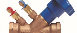
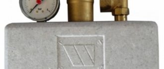
Rice. 3 Manual balancing valves for heating and hot water supply (DHW) systems in the house
Final Conclusion
If you install heating yourself, you will probably encounter balancing problems. When all radiators, except the last one, have balancing valves, the procedure will not cause much trouble. It is better to take valves that are adjusted with a key or a screwdriver, rather than with a plastic handle, so that children cannot reach them. It is possible that in winter the position of the spindles will have to be adjusted, because heat loss in rooms varies. The only caveat: do not make sudden movements and open the taps in cold rooms slowly, ¼ turn at a time.
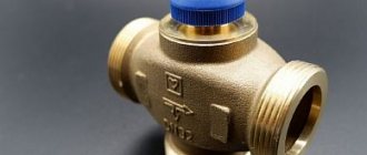
Design and operating principle
The principle of operation of balancing valves is to block the flow of liquid with a retractable valve or rod, causing a reduction in the cross-section of the passage channel. The devices have different designs and connection technologies; in a heating system they can additionally:
- Maintain the pressure drop at the same level.
- Limit coolant consumption.
- Shut off the pipeline.
- Perform drain functions for working fluid.
Structurally, balancing valves resemble conventional valves; their main elements are:
- Brass body with two through pipes with internal or external threads designed to connect to a line with standard pipe diameters. The connection in the pipeline, in the absence of a threaded fitting with a movable threaded nut (American), is made through its analogues - additional adapter couplings with different union nuts.
- A locking mechanism, the movement of which regulates the degree of blocking of the coolant passage channel.
Rice. 4 Danfoss LENO MSV-B manual balancing valve
- Adjustment handle with scale and setting indicators, allowing you to adjust the flow inside the device.
- Modern models are equipped with additional elements in the form of two measuring fittings, with the help of which the flow volumes (throughput) are measured at the inlet and outlet of the device.
- Some models are equipped with a shut-off ball mechanism that allows you to completely shut off the flow, or have the function of draining liquid from the water supply.
- High-tech modern types can be controlled automatically; for this, instead of a rotating head, a servo drive is installed, which, when power is supplied, pushes the locking mechanism, and the degree of channel closure depends on the amount of voltage applied.
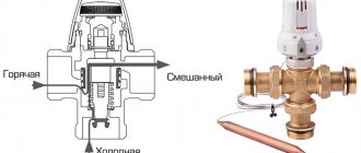
Rice. 5 Danfos AB-QM automatic balancers - design
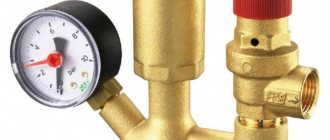
Balancing Tools
These include a balancing valve and a special measuring device.
A balancing valve is a type of shut-off valve for adjusting hydraulic resistance in heating systems. The device solves the problem by changing the cross-sectional diameter of the pipe.
Modern Y-type models are distinguished by the possibility of presetting, which limits the flow rate marked on the handle with a scale. The design provides for the presence of two nipples for measuring pressure, temperature, and coolant flow differential. The name is due to the shape of the body, where the cones are placed at an optimal angle to each other. This minimizes the influence of coolant flow on measurements and increases the accuracy of adjustment.
When to install
:
- The maximum load on the system does not provide a comfortable temperature.
- Under constant load, significant temperature changes are observed in the room.
- Normal heating power cannot be achieved.
The advantages of installing this device are as follows:
:
- Reducing fuel consumption and heating costs.
- Increasing the efficiency of the heating system and increasing comfort due to the ability to regulate the air temperature in each individual room.
- Makes it easier to start.
Modern balancing crane
Installation of a balancing valve requires the use of special fittings and adapters
It is important to pay attention to the presence of an arrow stamped on the body of the device and its direction. Some devices are mounted strictly in a certain direction of water circulation. Violating this manufacturer's recommendation will cause valve failure and system failure.
Once installation is complete, measurements should be taken to determine the level of adjustment.
Violating this manufacturer's recommendation will cause valve failure and system failure. Once installation is complete, measurements should be taken to determine the level of adjustment.
Pressure and temperature differences, as well as coolant flow across the balancing valve can be measured using a special device.
The multifunctional computer device is equipped with precise sensors, and in addition to the measurement function, it is capable of eliminating detected errors and carrying out balancing. This device greatly simplifies and speeds up the process of fine-tuning the heating system.
Manufacturers of modern devices provide the ability to connect them to a computer. Installing a special program allows you to transfer data to a PC for further work with them.
It is important not only to buy modern equipment, but also to know how to use it. Otherwise, the setup process will be ineffective, which will lead to improper heating operation, lack of a comfortable microclimate, excessive consumption of thermal and electrical energy
Methodology
:
- Using partner valves, the hydraulic system is divided into modules.
- Next, all parts are balanced, from risers and collectors to heating points. This makes it possible to achieve the design flow rates of all modules and valves with minimal pressure losses on the devices themselves.
- After balancing, the pump switches to the power that provides the calculated rate of water circulation in the system. This will allow you to adjust the flow rate on the main module located at the pump.
The result of adjusting the balancing valves is the data obtained about what values are required and achieved. This information allows you to check the quality of the work performed and is its guarantee.
Regulator with temperature control sensor for heating balancing
As a result of correctly performed balancing, the pumping equipment begins to consume a minimum of electricity, and the consumption of thermal energy is carried out rationally.
Another problem that one has to face in the absence of special devices is the inability to determine the quality of the heat supply when it is in operation. Y-type balancing valves with measuring nipples have a system self-diagnosis function, which consists of the following:
:
- Determining the malfunction while the heating system continues to operate.
- Checking the technical condition and operating parameters of equipment.
- Making decisions when identifying faults.
Thus, errors are found and quickly eliminated.
Types of balancing valves
Balancing in heating systems is carried out using two types of control valves:
- Manual . The design is a body made of non-ferrous metals (bronze, brass), which houses a balancing element, the degree of extension of which is set by turning a mechanical handle.
- Automatic . Automatic devices are installed on the return pipeline together with partner valves that can limit the flow of the medium by presetting the throughput. When connected, they are connected to partners via an impulse tube connected to the built-in measuring nipple. If the fitting is installed to supply water in a direct line, its handle is red; when installed in a return line, it is blue (Danfoss models). Automatic types include models controlled by a servo drive, which is supplied with constant voltage.
Advantages of fittings
Manual balancing valves have many advantages. They are cheaper than automatic models. In addition, they are distinguished by the following features.
- Increased reliability.
The device operates stably even under conditions of increased loads and significant pressure fluctuations. - Maintainability.
This type of fittings has a simple design, which very rarely fails and can be easily repaired if necessary. - Easy setup.
Using the screw handle, you can set the required operating parameters in just a couple of minutes. - Balancing accuracy.
Several positions, clearly indicated on a special scale, allow you to fine-tune the operation of the system. - Functionality.
The valves are excellent for operating in systems with different operating environments and settings. - Blocking the flow.
If necessary, the device can serve as a shut-off valve. In this case, you can stop the flow without changing the settings made. - Easy installation.
The valve is quickly installed on the pipeline using flanges or internal threads, creating a strong and tight connection. - Removable handle.
When operating the valve in cramped conditions, the handle can be removed and the device can be controlled using a hex key. - Internal drainage.
The device has built-in pipes that can be used for quick two-way drainage of the system.
Balancing valve for heating system
Existing heat supply systems are conventionally divided into two types:
- Dynamic. They have conditionally constant or variable hydraulic characteristics, these include heating lines with two-way control valves. These systems are equipped with automatic balancing differential regulators.
- Static. They have constant hydraulic parameters, include lines with or without three-way adjustment valves, the system is equipped with static manual balancing valves.
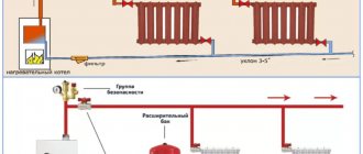
Rice. 7 Balancing valve in the line - installation diagram of automatic fittings
In a private house
In a private house, a balance valve is installed on each radiator; the outlet pipes of each of them must have union nuts or another type of threaded connection. The use of automatic systems does not require adjustment - when using a two-valve design, the supply of coolant to radiators installed at a large distance from the boiler is automatically increased.
This occurs due to the transfer of water to the actuators through a pulse tube under lower pressure than that of the first batteries from the boiler. The use of another type of combined valves also does not require calculating heat transfer using special tables and measurements; the devices have built-in control elements, the movement of which occurs using an electric drive.
If a manual balancer is used, it must be adjusted using measuring equipment.
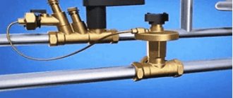
Rice. 8 Automatic balancing valve in the heating system - connection diagram
To determine the volume of water supplied to each radiator and, accordingly, balancing, an electronic contact thermometer is used, with which the temperature of all heating radiators is measured. The average supply volume per heater is determined by dividing the total value by the number of heating elements. The greatest flow of hot water should flow to the furthest radiator, a smaller amount to the element closest to the boiler. When carrying out adjustment work using a manual mechanical device, proceed as follows:
- Open all control valves all the way and turn on the water; the maximum surface temperature of the radiators is 70 - 80 degrees.
- Using a contact thermometer, measure the temperature of all batteries and record the readings.
- Since the furthest elements must be supplied with the maximum amount of coolant, they are not subject to further regulation. Each valve has a different number of revolutions and its own individual settings, so the easiest way is to calculate the required number of revolutions using the simplest school rules based on the linear dependence of the radiator temperature on the volume of passing coolant.
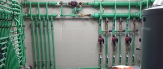
Rice. 9 Balancing fittings - installation examples
- For example, if the operating temperature of the first radiator from the boiler is +80 C., and the last +70 C. with the same supply volumes of 0.5 m3/h, on the first heater this indicator is reduced by a ratio of 80 to 70, consumption will go less, and the resulting volume will be 0.435 m3/h. If all the valves are not set to the maximum flow, but set to the average value, then you can take the heaters located in the middle of the line as a guide and similarly reduce the throughput closer to the boiler and increase it at the farthest points.
In a multi-storey building or building
The installation of valves in a multi-storey building is carried out in the return line of each riser; if the electric pump is far away, the pressure in each of them should be approximately the same - in this case, the flow rate for each riser is considered equal.
To set up in an apartment building with a large number of risers, it uses data on the volume of water supplied by an electric pump, which is divided by the number of risers. The resulting value in cubic meters per hour (for the Danfoss LENO MSV-B valve) is set on the digital scale of the device by rotating the handle.
What is it needed for?
A valve is an element of a heating system that allows the source of thermal energy to be evenly distributed throughout all rooms of a residential building. Since the coolant, following the path of least resistance, first enters the nearest risers of the building, and more distant risers, as a rule, have a lower temperature, the coolant simply does not reach them. To correct this situation, a balancing valve is used.
The valve serves to create artificial resistance along the path of the water. Thus, not the entire volume of water flows to the nearest area; the flow is distributed so that the coolant also flows to distant risers. In order to correctly install balancing valves, design organizations first make a hydraulic heating calculation. During the calculation, the difference between the upper and lower pressure values on each riser of the building is determined. Therefore, valves are also called differential pressure regulators.
Each valve is configured individually, taking into account the calculations made for the functioning of the system. Thus, the main purpose of the valves is to link together the circuits of the water heating system. The functions of the valve also include limiting water flow by consumer groups and balancing recirculation pipelines for hot water supply and heating and cooling ventilation systems.
Valve installation
When installing the valve, it is necessary to place it in the direction of the arrow on the body, which indicates the direction of fluid movement, to combat turbulence, which affects the accuracy of the settings. Select straight sections of pipeline with a length of 5 diameters of the device and its location points and two diameters after the valve. The equipment is installed in the return branch of the system; a plumbing adjustable wrench is sufficient to carry out the work; installation is carried out in the following sequence:
- Before installation, be sure to flush and clean the pipeline system to get rid of possible metal shavings and other foreign objects.
- Many devices have a removable head; for ease of installation in pipes, it should be removed in accordance with the instructions.
- For installation, you can use flax fiber with appropriate lubricant, which is wound around the end of the pipe and the battery outlet fitting.
- The control valve is screwed onto the pipe at one end, the other is attached to the radiator with special washers (American adapter coupling), which is placed on the outlet radiator fitting or screwed into the valve, playing the role of a connecting coupling.
Purpose
A balancing valve in a heating system is used to ensure proper distribution of heat transfer. That is, there are times when in one room the batteries are hotter than required, and in another they are much colder than desired. That is, improper distribution of the coolant occurs. This means that adjustment is required to correct this situation.
A balancing valve is a type of shut-off valve through which hydraulic resistance is regulated. This is achieved by changing the cross-sectional diameter of the pipe in a certain area.
Recently, when designing heating (for both multi-apartment and private houses), a balancing valve is immediately added to the system. However, what should owners of ready-made heating systems do?
There are several “symptoms” that indicate the need to install shut-off valves of this type:
- Lack of comfortable temperature even at maximum load.
- Significant fluctuations in room temperature with a constantly equal load in the heating system.
- Difficulties in starting the system - inability to reach rated power.
All this indicates that it is necessary to install a balancing valve and carry out regulation. It will allow you to adjust the flow of coolant to one or another part of the system.
Benefits of use
Installing a balancing valve will help solve the above problems in heating operation.
In addition, the following advantages of using this equipment can be highlighted:
- Reduced costs - that is, owners of private houses note that after balancing the system, the amount of fuel consumed decreases.
- Increasing indoor comfort - you can achieve a more suitable temperature level for each individual room.
- No difficulties during startup - the use of balancing fittings will simplify the startup of the system as much as possible.
Installation
Including equipment in the system
Balancing valves for heating are most often used to adjust two-pipe heating systems.
Read about them in detail here - https://kvarremontnik.ru/dvukhtrubnaya-sistema-otopleniya/
The element is installed using special fittings and adapters. In this case, you should be careful: some taps can be installed on pipes with a certain direction of coolant movement.
On such taps there is a special arrow that shows in which direction the water should move in the pipe. If you install the valve without following this instruction, an attempt to regulate the system with its help may result in breakdown of the element itself and malfunction of the entire heating system.
Regulation
After installing the valve, using special equipment, measurements are taken to determine to what level adjustment is required. Some experts call this method quite labor-intensive.
Important: before carrying out the balancing procedure, you should start the heating system and connect the necessary measuring equipment - this will make it possible to determine the quality of work.
More accurate balancing results can be obtained by dividing the heating system into separate segments and adding balancing fittings to each of them. In this case, the balancing procedure itself will take considerable time - it will be necessary to adjust each individual valve. But the results will be much better.
Setting the balance valves
To balance the heating in a private house, select manual devices of the required diameter, selecting and configuring them using the appropriate diagram included in the passport. The initial data for working with the graph are the supply volume, expressed in cubic meters per hour or liters per second, and the pressure drop, measured in bars, atmospheres or Pascals.
For example, when determining the position of the adjustment indicator of the MSV-F2 modification with a nominal bore DN equal to 65 mm. at a flow rate of 16 cubic meters per hour. and pressure drops of 5 kPa. (Fig. 11) on the graph, connect the points on the corresponding flow and pressure scales and extend the line until the conventional scale intersects the coefficient Ku.
From the point on the Ku scale, draw a horizontal line for diameter D equal to 65 mm, find the setting with the number 7, which is set on the handle scale.
Also, for the selected diameter of the device, its adjustment is carried out using the table (Fig. 12), from which the number of spindle revolutions corresponding to a certain flow is determined.
Rice. 11 Determination of the position of the valve scale at a known pressure and a certain water supply
Rice. 12 Example table for manual configuration
Computational modeling
The most constructive and correct adjustment method is by constructing a calculation model of the hydraulic heating system.
This can be done in software such as Danfoss CO and Valtec.PRG, or in paid products such as AutoSnab 3D. You should not be afraid of paid software: as you will see later, its cost cannot be compared with the costs of special automatic balancing devices, while the design design of the hydraulic system will provide a complete picture of the system, its operating modes and the physical processes occurring at each point . Balancing using software calculations is carried out by constructing an exact virtual copy of the heating system. In different working environments, the modeling mechanism proceeds with some differences, however, all programs of this kind have a friendly and user-friendly interface
It is very important that the construction is carried out truly accurately: indicating each fitting, fitting element, turns and branches present in the real system. Here are the initial data you will need:
- Boiler specifications: power, efficiency, pressure-flow curve, operating pressure.
- information about the circulation pump: flow rate and pressure;
- coolant type;
- material and nominal diameter of pipes, ambient temperature;
- technical information about all shut-off and control valves, local resistance coefficients (KMR) of each element;
- passport data for shut-off valves, the dependence of their capacity on pressure drop and degree of opening.
After building a system model, all work comes down to ensuring equal coolant flow on each radiator. To do this, artificially reduce the throughput of shut-off valves on those radiators and circuits where there is a significant increase in flow compared to others. When virtual balancing is completed, Kvs - throughput coefficients - are written out for each radiator. Using a table or graph from the valve data sheet, the required number of revolutions of the adjusting rod is determined, after which this data is used to balance the real system in situ.
Recommended Manufacturers
Several global manufacturers are engaged in the production of such shut-off and control valves. The operation of the heat supply depends on the quality of materials, accuracy of settings and design. Therefore, it is recommended to buy original models rather than analogues. This will increase the reliability of the system.
You can find balancers on the market from Valtec, Danfoss, Herz and Honeywell. They differ only in appearance, their functional features are the same. The table shows popular heating balancers from these manufacturers.
| Manufacturer | Mechanical balancer | Automatic balancer |
| Valtec | VT.042.G | VT.040.G |
| Danfoss | Leno MVT or MNT | AB-PM, APT or ASV |
| Herz | 4017 M | TS-V |
| Honeywell | Kombi-3-Plus | — |
These models differ in size and connection methods to the pipeline. Some of them are designed only for cold water supply, but most are universal and can be used for heating and water supply. An example is Danfoss products.