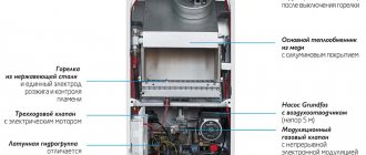
The manufacturer Buderus, part of the Bosch group of companies, produces heating equipment of various models, which are characterized by traditional German quality and reliability.
Buderus boiler errors are various problems in operation: from minor failures in which the equipment continues to function, to malfunctions that cause it to shut down. Failures invariably occur during the operation of the heating system, and in order for the boiler to last a long time, but without having to call a technician at every display signal, the user needs to learn how to decipher the most common Buderus error codes and correct minor problems with their own hands.
Buderus boiler error 6a
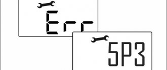
Error buderus 6a (second indicator flashes) occurs when the boiler does not detect a flame on the burner.
Flame control is one of the most important functions of a safety system. To control the flame, there is a special electrode on the burner through which a small current flows during combustion. The control board constantly records this current. If for some reason the current at the ionization electrode disappears, error 6a occurs. The same thing will happen, for example, after several unsuccessful attempts to ignite the boiler - this is the most common situation. The reasons are standard for all boilers:
- incorrect adjustment of the gas valve (insufficient supply gas pressure)
- poor contact or lack of signal from the flame ionization sensor
- malfunction of the flame control sensor (contamination, breakdown)
- failure of the control board (repair of the boiler control board is required)
- incorrect electrical connection of the boiler (lack of grounding)
- lack of air for proper combustion (lack of draft, clogged inlet pipe)
Error buderus 6a is classified as critical, which means that after such a malfunction occurs, the boiler will not start on its own - the error must be reset!
There are two options to reset the error:
- keep the OK button pressed until the fault signs disappear, the boiler starts working again and the display shows the flow temperature.
- Turn the boiler power on and off
Gas valve
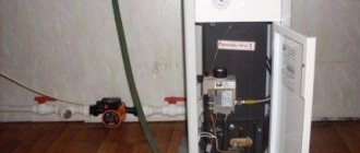
The gas valve is located in the middle. This is not a Buderus boiler, but it uses exactly the same valve
This test step involves the resistance of the modulation and blocking coils. Verification steps:
If an open circuit is detected on any of the locking coils, then the locking coil block will need to be replaced.
Main malfunctions of Immergas gas boilers
The most common problem is with the ignition of the burner.
It is indicated by code 01 and can have several reasons:
- Gas supply problems. There may be a lack of pressure in the gas pipeline, a closed gas valve, a gas valve failure, or other problems.
- Poor condition of burner nozzles. They may be clogged with soot and soot.
- Incorrect power connection. All European boilers are phase-dependent and require a specific connection of all electrodes and mandatory grounding. If the connection is made incorrectly, upon startup the boiler is immediately blocked and cannot start working.
NOTE! Sometimes the boiler suddenly stops starting for unknown reasons. You should check the connection of the electrodes on the common panel; perhaps they were accidentally mixed up during repairs. The second common problem is overheating of the boiler
The second common problem is boiler overheating.
It can also be caused by several reasons:
- The fluid circulation rate has dropped due to problems with the pump.
- Too hard water has caused the formation of a layer of scale inside the heat exchanger, which is a natural heat insulator and reduces heating efficiency. This caused the combustion regime to intensify. A situation has arisen when, in order to obtain the required temperature, the heat exchanger has to be heated more strongly, which causes excessive load on the metal, increases gas consumption, and prematurely destroys all components of the boiler.
Another error that often appears on the display is the presence of a stray flame (error 20). The system sees a flame on the burner, which is currently turned off.
The reasons for this condition may be:
- Presence of condensation drops on the control board.
- Due to poor-quality grounding, a static charge appears, which is perceived by the system as a signal from a burning flame.
In addition to these errors, there may be other, less frequent and not detected by electronics:
- The smell of gas indicates a leak.
- Failure of the pressure switch during startup, requiring cleaning of the chimney.
- A weak orange flame indicates that the injector channels are clogged with soot or soot.
Most errors that occur for the first time are cleared immediately. This is done because the boiler electronics are highly sensitive and often mistake electrical interference for sensor signals.
However, if the error appears again and again, you should immediately contact service.
Diagnostics and repair
The most common error appearing on the Buderus boiler display is error 6A. It stands for “problems with ignition.” You can try to diagnose it yourself, identify the cause and fix the problem.
If this error occurs, you must first perform the following steps:
The problem may be an accident on the gas main with the gas turned off, so the automation has blocked the boiler. If the gas supply is restored, the boiler will turn on as normal.
If this error occurs again, the following measures must be taken:
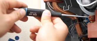
Now, armed with a Phillips screwdriver, you need to expand the control panel. For these purposes, unscrew 2 screws located at the bottom. After removing the bolts, the panel must be carefully lowered down and turned towards itself.
To remove the front panel, you need to unscrew 2 screws. On the contrary, this panel must be lifted in order to be removed from the boiler. To determine the condition of the gas burner, ignition electrodes and flame control, it is necessary to dismantle the boiler firebox cover. Using a screwdriver, you need to unscrew 5 screws. Next, lower the lid a little and remove it.
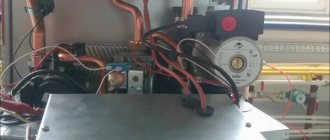
The firebox contains a primary copper heat exchanger, a gas burner, an ignition electrode on the right side, and a flame control electrode on the left.
The error does not clear
Sometimes users and specialists who carry out diagnostics cannot reset the error and conclude that the control unit is faulty. The main reasons why the error may not be reset:
- the error cannot be reset until the fault has been eliminated (for example, lack of pressure in the boiler)
- poor contact between the reset button and the control board (often seen on Vaillant TEC boilers)
- the reset order is broken (in some cases you need to hold Reset for a certain time)
- A malfunction of the information board (display board) is rare, but possible.
At the same time, when the user’s board is changed, everything works because there is no error on it. Everything will work until the next error appears, and if the reason is not figured out, they will replace a working board every time.
From practice, we often received serviceable units for repair that simply had not cleared the error. It is often impossible to convince (especially specialists) that there is a possibility of a problem with the error reset. “We know everything, we can do everything, 20 years of experience - we checked everything, the error does not reset - the control board is faulty!”
Advantages of the Buderus Logamax U072 boiler
Among the main positive aspects are:
- affordable price;
- versatility and modern style;
- small size saves usable space;
- updated user interface;
- informative LCD display;
- works on the basis of a plate heat exchanger;
- you can connect a room thermostat;
- low noise level;
- modulating fan;
- minimal risk of installation errors.
Even the most serious and durable equipment can break down from time to time. But you can deal with some problems yourself.
Buderus boiler connection diagrams
There are standard classic diagrams, illustrated in the installation instructions for Buderus boilers of one series or another. However, in practice, the diagrams almost always undergo changes to optimize the wiring, adjust to the geometry of the furnace room and the relative position of individual components of the heating system.
The heating systems of country houses, although similar to each other, are only in general terms. In reality, no matter how diverse the areas and layouts of buildings are, their heating systems are just as different. Departures from standard schemes can also be caused by:
- connecting the pool heating heat exchanger,
- placing a volumetric buffer tank to which you plan to connect alternative heat sources: solar collectors, solid fuel boiler or fireplace insert with a water circuit.
Complications of the circuit cannot be avoided when implementing the connection scheme for Buderus cascade boilers, when the system is designed to use several gas boilers operating together or alternately. A modern approach to building such systems is the use of special units - hydraulic arrows, which ensure equalization of temperatures and pressure of the coolant in several circuits connected to it.
Popularity of the German manufacturer
There are hundreds of companies that produce gas boilers, but German products are an order of magnitude superior to them in reliability and quality. What is the reason? The basis of the highest quality, the famous German quality, is pedantic and careful design, scrupulous selection of materials and components. After the prototype has been manufactured, tests are carried out and the design is adjusted based on the test results, and only then the production of the product begins.
Therefore, boilers from German companies are popular all over the world. They have proven themselves to be reliable, durable and economical devices with high efficiency. For example, Buderus convection gas boilers have an efficiency of up to 97%.
Measuring instruments for setting up heating systems
Due to rising energy prices, proper adjustment of heating equipment is becoming an important component for optimizing utility costs. Testo portable flue gas analyzers will help you complete any task of setting up, commissioning and servicing heating equipment
Professional gas analysis with testo 330-1 LL h4>
The testo 330-1 LL gas analyzer with extended sensor life is a reliable device for diagnosing faults in heating equipment and for monitoring the level of emissions of harmful substances into the atmosphere or for the daily work of heating system specialists. It is able to meet the highest demands placed on a gas analyzer: the highest sensor accuracy and sensor service life.
Professional gas analysis with testo 330-2 LL h4>
In addition to all the advantages of the Testo 330-1 LL gas analyzer, you can use the testo 330-2 gas analyzer with higher CO concentrations in the flue gases. This is achieved through the built-in function of automatically diluting the flue gas sample with a factor of 5. You will receive additional convenience by using the pressure/draft sensor zeroing function with the probe remaining in the chimney.
Highly efficient gas analysis with testo 320
h4>
Gas analyzer Testo 320 is a multifunctional flue gas analyzer for heating system specialists. The intuitive menu structure and ease of operation of the testo 320 gas analyzer, combined with a high-resolution color display, allow you to carry out all the necessary measurements during installation, commissioning, service and maintenance of heating boilers and burners.
Basic level gas analysis testo 310 h4>
The testo 310 gas analyzer combines ease of use with high measurement accuracy and is ideal for all basic measurements on gas boilers and burners. The long battery life guarantees the possibility of long-term use of the device, including for a series of measurements of flue gas concentrations
Soot number analyzer Testo 308 h4>
The Testo 308 soot number analyzer helps you measure the soot number. The built-in pump and the automatic display of the measured value on the backlit display allow you to obtain data on the soot content in the chimney using a modern measurement method. This measurement method is comparable to traditional soot number measurement methods using a hand pump.
Easy management of measurement data with easyHeat software h4>
With Testo's dedicated software, you can easily transfer data from your gas analyzer to a PC for further processing. A wide range of functions, such as customer data and measurement management, allows you to optimize the work of planning service activities at your customers' sites.
Useful tips
Checking all electrical circuits
Errors that appear on the Buderus display are generated in the electronic board of the boiler based on signals received from the corresponding sensors. The first step in solving any problem should be to check all electrical circuits. Loose contacts, oxidized lamellas - this can be eliminated in a few minutes. It will not take much more time to replace the wire in case of insulation melting or breakage.
Instability in the power supply often triggers Buderus errors. This often manifests itself at sites in intensively built-up areas. Periodic switching on of welding machines and powerful heaters leads to voltage surges and phase imbalance. The conclusion is simple: before searching for the cause of the boiler error display, you need to check the parameters of the supply network.
Uninterrupted operation of Buderus is ensured by its connection via a UPS. The stabilizer will not give the desired effect, especially since it is provided for in the electronic circuit of the boiler. The power supply supplies voltage even if there are problems with power lines due to the built-in batteries; depending on their total capacity from 2 to 14 hours. For suburban properties this is a more than rational solution.
Not everyone carefully reads the manufacturer's obligations. One of the guarantee conditions for Buderus is professional installation. The absence of a service organization mark in the boiler passport is the reason for refusal in case of user complaints. In order not to pay for warranty service or repair of heating equipment out of your own pocket, it is better not to do independent installation and piping (in order to save money) with Buderus.
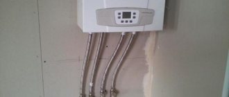
Piping a gas boiler in the heating system
After the wall-mounted gas boiler has been installed and the heating device is placed on the wall, the first thing you need to do is connect it to the heating system. Depending on which model is installed, single-circuit or double-circuit, there are different piping schemes. We will look at the connection process using the example of a wall-mounted double-circuit gas boiler.
Photo 1: Connection diagram for a wall-mounted double-circuit gas boiler
As you know, a double-circuit boiler, in addition to heating, is capable of producing hot water for household needs. Structurally, this is realized by installing one bithermal or two separate heat exchangers. A double-circuit boiler does not produce very much hot water, but it is quite enough for 1-2 distribution points (for example, a kitchen faucet and shower).
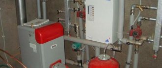
A modern wall-mounted gas boiler is very compact and already contains within itself the basic elements necessary for the operation of a heating system with forced circulation, such as: a circulation pump, an expansion tank, a safety group. In the heating systems of small private country houses, this is more than enough, but if necessary, you can install an additional expansion tank or another pump.
At the bottom of any mounted double-circuit boiler there are 5 pipes. They are connected to: supply and return lines of the heating system, supply and return of hot water supply, main gas. The gas connection is usually located in the center and is colored yellow. All other lines can be located in any order, depending on the model of the gas boiler. Therefore, before starting tying, it is necessary to clarify the purpose of each of them in the operating instructions.
Photo 2: Piping diagram for a wall-mounted double-circuit gas boiler
The piping of a wall-mounted gas boiler is done with polypropylene or metal pipes. The cross-section of heating pipes is usually larger than DHW pipes 3/4 and 1/2 inches, respectively. The heating system is connected to the boiler through American nuts. Ball valves are installed on each line for the convenience of dismantling the gas boiler without draining the coolant and to isolate the boiler from the heating system if necessary. To ensure tightness, all connections must be made using plumbing FUM tape or flax.
Coarse filters must be installed in the heating return line and in the DHW supply line. For ease of washing and cleaning, they are also cut off by shut-off valves. Often, in order to increase the service life of the secondary heat exchanger of a double-circuit boiler, a magnetic fine filter is additionally installed at the DHW supply.
Problems not shown on the display
When they occur, the Buderus error is not displayed, but a number of signs indicate incorrect operation of the boiler or the entire heating system.
Adjusting the circulation pump
1. Slow heating of batteries; noise of fluid circulating along the circuit. The main reason is the incorrectly set pump speed. The switch is located on its body.
2. “Difficult” ignition, boiler efficiency is lower than declared. There are several options: from poor burner performance to the use of gas with characteristics that do not meet the manufacturer’s requirements.
Recommendation: carry out Buderus service, check the set parameters.
The article provides explanations for all problems that can be resolved independently. It’s better not to go deeper - the boiler is expensive, and unprofessional intervention in its operation will not lead to anything good.
Features of the Buderus Logamatic 2107 control system:
- Designed for a low-temperature boiler installed in a one or two-family house;
- The MasterController microprocessor board performs regulation, control and monitoring tasks. It enables the implementation of special Logamatic functions, including: automatic heating curve detection to smoothly reduce the boiler water temperature depending on the outside temperature, pump logic to protect against condensation, dynamic switching for optimal burner control, priority hot water heating and optimized hot water heating water;
- Safety devices;
- Quick expansion of functions by installing additional modules: FM241 (control of one heating circuit with an actuator), FM242 (for control of a two-stage or modulating burner), FM244 (for control of a solar collector). In addition, it is possible to install a BFU or BFU/F remote control (with a radio clock for automatic summer/winter time switching).
The Buderus Logamatic 2107 control system provides one important function - economical and environmentally friendly heating mode, by reducing the number of burner starts.
All Buderus Logamatic control systems are supplied in a housing made from recyclable plastic, with a universal quick installation system, color and number coded connectors, fully wired and protected against TV and radio interference.
Source
Spark test
The algorithm for checking the spark is as follows:
- connect the unit to the electrical network;
- restart the device by clicking “Reset”.
The spark should strike consistently, which means the problem is elsewhere. Turn off the power supply and continue searching for the cause of error 6A on the Buderus boiler.
Check if the spark plug produces a spark
User manual
The boiler is connected immediately after installation in a pre-designated location.
The necessary communications are connected:
- Direct and return pipelines of the heating system.
- Water supply pipeline.
- Gas pipe.
- Power supply.
After connecting all pipelines, the tightness of the connections is checked, in particular it is necessary to pay attention to the gas pipes. Then the system is filled with water
This situation occurs not only during the first start-up, but also after switching the unit to the winter period. When filling, follow the readings of the pressure gauge - the operating pressure is in the range of 1-2 Bar, but you need to fill water only to the minimum so that, expanding when heated, the liquid does not rupture the boiler
Then the system is filled with water. This situation occurs not only during the first start-up, but also after switching the unit to the winter period. When filling, they are guided by the readings of the pressure gauge - the operating pressure is in the range of 1-2 Bar, but you need to fill in water only to the minimum so that, expanding when heated, the liquid does not rupture the boiler.
Do not fill a hot boiler with cold water. This will cause destruction of the heat exchanger, the occurrence of deformations or cracks.
After filling the system, the desired coolant temperature is shown on the display. This will start the burner and start the boiler. The mode is adjusted in working order; switching from summer to winter is carried out when appropriate weather and climatic conditions occur.
Error 4C (first indicator blinks)
The error occurs either when there is insufficient pressure in the heating system, or when the temperature at the outlet of the primary heat exchanger is too high. You need to check the pressure gauge reading. If the pressure in the system is insufficient - less than 0.5 bar, it is necessary to recharge the boiler. Too high a temperature on the heat exchanger can also be caused by problems with coolant circulation or air lock. The source of the error is either a hydraulic pressure switch or a boiler water temperature limiter - a thermostat, which is located immediately at the outlet of the heat exchanger.
All main error codes and their interpretation
Let's look at the main error codes for Buderus boilers:
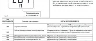
| Code | Decoding | Ways to fix the problem |
| H11 | Problems with the DHW temperature sensor | Check the contact group, determine the functionality of the sensor, and replace if necessary |
| 2P | Coolant overheating | Check the contacts, determine the condition of the circulation pump |
| 3A | Fan stop | Check the contacts, replace the fan with a new one |
| 4C | Heat exchanger overheating | Stop the boiler, check the functionality of the circulation pump and the extract air temperature sensor, call a technician |
| 4U, 4Y | Short circuit or break in the forward line (supply) temperature sensor | Check the condition of the sensor and contacts, clean and reconnect them, if necessary, replace the sensor |
| 6A | No flame | Check the presence of gas in the system and in the boiler equipment, call specialists |
| 3C, 3L, 3P, 3Y | Fan failure | Check connection and functionality, replace |
| 6C | The system sees a flame on an idle burner | Moisture on contacts or control board, poor ground contact |
Error 4Y (first two lights flash)
The flow temperature sensor is faulty. For diagnostics, you need to measure the resistance at the sensor contacts. At room temperature it should be within 10 kOhm, the sensor connection must be reliable, because in case of a break there will also be an error. The logic of the CL error is the same, only for the DHW temperature sensor. If the temperature sensor malfunctions, the boiler operation is blocked, only the circulation pump remains running to prevent freezing. If the DHW temperature sensor is damaged, the boiler operation will not be blocked.
Malfunctions and expert advice
No one is immune from boiler breakdowns, however, to reduce them to a minimum, it is best to trust the installation of equipment to highly qualified professionals and masters of their craft.
Since gas boilers from this brand are automatic, all possible errors associated with equipment breakdowns and malfunctions are displayed on a convenient LED display. To reset the error, you can reboot the boiler, since sometimes there are regular failures and errors that appear on their own, even if everything is fine with the boiler. To do this, you need to hold the reset button for about 4-5 minutes, but if the error code is displayed again, it will still have to be eliminated.
Error codes and ways to solve them are indicated in the instructions, which should be studied in detail before putting any boiler model into operation.
Let's look at the list of the most common faults.
Burner not turning on. To solve this problem, you should switch the heating regulators and control system to the “on” mode. With this problem, the gas exhaust sensor very often triggers. If after 15-20 minutes the operation of the boiler has not been restored, the chimney shaft should be cleaned, and it may also be necessary to purchase new sensors that have failed.
If there is no spark in the boiler, you should pull out the ignition cable and turn on the ignition. If outside sounds are heard during this process, the burner will most likely need to be replaced. Sometimes the reason may be in the electrodes. If there are no sounds, the transformer should be inspected.
If the burner does not light, and all methods have already been tried, then most likely the problem is accumulated air, which should be removed
To do this, you need to open the gas valves, measure the pressure and only then remove excess air.
If there is no current, it is very important to check all connections according to the instructions and assembly of the boiler model. It is very important to be mindful of tension as well as loose connections.
When the current is low, it is important to clean the electrodes - most likely they are clogged.
Since some parts of boilers are very often exposed to moisture, they should be monitored, otherwise over time they may oxidize and become unusable. It is best to carry out timely cleanings rather than purchasing new expensive parts. Cleaning is especially recommended if the sound of boiling water is heard in the boiler. Many professionals agree that any boilers need to be inspected by a specialist at least once a year or a year and a half.
It is especially common to meet customers who have a problem with the heat exchanger. This is due to the fact that it is on this device that deposits of salts most often occur, which adversely affect even the highest quality metals, contributing to their destruction.
If very loud noises are heard during prolonged heating of water, this may also be due to the formation of salts, plaque or scale on the internal parts of the boiler. Sometimes problems can be caused by improperly configured hardware.
Replacing the locking coil unit
To remove the coils you will need to unscrew the screw holding them. Pull them towards you and remove them from the valve. It is not difficult to purchase a new block of locking coils. There are quite a lot of them in specialized online stores and they are not in short supply. Replacement occurs in the reverse order: you need to install the block in its place, tighten the screw and check the resistance of the new block again.
Boiler gas valve
Reconnect the connectors to the coil, put the side panel in place and secure it with screws. Put the seal back on. Connect the control panel clamps and the ignition electrode connection cable connector.
To check operation, you need to connect the power supply, open the gas supply valve and turn on the boiler. If everything was done correctly, then the fan will be activated, the pump will start, the gas burner will ignite, error 6A for the Buderus boiler will disappear and the boiler will start working as usual.
If the necessary tool is not at hand or the owner of the house is not confident in his own abilities to identify the problem and fix it, it is better to entrust the work to a specialist.
User manual
Operating the boiler is not particularly difficult. The user is not required to perform any special actions other than the current temperature setting or switching the boiler to winter or summer mode.
In addition, in the summer you need to drain the water from the heating system, and at the beginning of the next season you need to fill the system again. This is also performed by the user, guided by the readings of the pressure gauge on the unit body.
If an error appears on the display, you must reset it by pressing the “OK” button and holding it in this position until the error disappears.
This is done because the control panel often perceives voltage surges as signals from the corresponding self-diagnosis sensors. If it appears again when you restart it, you need to call a technician.
Gas pressure and automation
A micromanometer will be required for this test step. It must be turned on, but before starting work it is important to calibrate the device by pressing the “zero” button. For ease of work, experts recommend dismantling the left side panel. You will need to unscrew a number of screws holding the panel on the front and bottom. Further work is carried out according to the following plan:
The gas inlet pressure is normal, so you need to continue looking for the error 6A problem.
Error 6A
Error 6A, displayed on the display of wall-mounted gas boilers Buderus Logamax U 072 on absolutely all models with a power of 12, 18, 24, 28 and 35 kW, signals the absence of a flame on the burner. To control the flame in the combustion chamber, an ionization electrode is installed on the burner, through which a small current flows during gas combustion, that is, a certain amount of free electrons and negative ions, which are transmitted to the control board via wire. If for some reason the ionization intensity drops below a certain level, the control board, after three attempts to ignite the burner, displays an error code on the display and the boiler goes into trouble!
This malfunction is extensive and a large number of elements will have to be checked.
You need to start with the most basic thing, this is to make sure that the gas valve is open, what if someone turned it off, and that’s why there is no gas!
Secondly, you need to make sure there is sufficient gas inlet pressure. To do this, connect a pressure gauge to the gas valve fitting and make sure that the pressure is between 17 and 25 mbar.
Third, while the pressure gauge is connected to the gas valve, check that the gas operating pressure adjustment in the minimum and maximum modes is consistent. But this is only in the case when the boiler can work for a short time after resetting the error. If the boiler does not start, then you will not be able to do this.
Fourthly, you need to check the gas fittings themselves for the presence of power and the serviceability of the coil and solenoid valve.
If anything is faulty, the gas fittings must be replaced.
Then we move on to inspecting the electrode and wires. Here you need to check the wire for breaks and its reliable connection to the electrode and the control board. There should be no cracks or chips on the ceramic part of the electrode, and the metal rod itself should be clean and located at a distance of about 8 mm from the burner.
Next, fifthly, be sure to check the flue gas system for correct assembly and, as trivial as it may sound, for the absence of foreign objects and debris in it. And if the malfunction appears in winter, then there is a possibility of ice forming on the chimney head.
Sixthly, the heat exchanger and burner in the combustion chamber must be clean and free of dust and soot. Otherwise, the lack of proper combustion due to lack of oxygen and carbon deposits can lead to incorrect readings from the ignition electrode, and to be honest, you don’t want to suffocate from carbon monoxide! I recommend maintenance at least once a year!
And lastly, seventh, this is a malfunction of the board, which can be checked with a multimeter by measuring the voltage on the coil and electromagnet. If there is no voltage, then you need to replace the board with a new one!
This error 6A is critical and after eliminating the fault the boiler will not start on its own, so you need to manually press the RESET button and reset the error.
Using the sequence when troubleshooting, you can eliminate any non-functioning component and start the boiler so as not to freeze in winter. If I helped you solve the problem, then I did everything right! Support me with your thumbs up and subscribe to the channel! Until next time, see you!
Error 3u, or 3c
The causes of the malfunction in the event of error 3c are similar to the reasons for error 3a, as well as the methods for eliminating them. Another factor, if this code appears on the indicator, can sometimes be the formation of condensation on the differential relay. To fix it, remove the relay, dry it with a hairdryer and reinstall it.
The number 3 in combination with the letter “y” or “c” (depending on the model - 24 kW double-circuit Buderus, or other power, or single-circuit, etc.) signals a malfunction of the gas boiler pressure switch.
This malfunction can be caused by a clogged gas removal channel or improper operation of the fan (at too high a speed). The channel is easy to clean, and the fan speed can be adjusted using the instructions in the equipment operating manual.
If the test does not show either one or the other, to stop error 3c you need to inspect the relay to see if it works when the contacts close or open. If not, replace this part of the system.
If such an error occurs, the boiler control board does not receive a signal from the differential pressure switch, that is, its contacts do not close after the fan starts. The pressure switch is used to determine the necessary conditions for removing combustion products.
The procedure for putting the boiler into operation is as follows:
- The control unit gives a signal to start the fan
- The fan creates the necessary vacuum in the exhaust pipe
- The differential relay registers the vacuum and the microswitch contacts close
- The board sends a signal to open the gas valve and ignite
Therefore, to understand the problem, you need to determine at what specific moment the boiler goes into error. If the fan starts, but the relay does not click, it is tedious to inspect the supply pipes; perhaps there is a blockage or condensation, or there is actually a blockage in the chimney itself.
If the fan does not start, you need to check whether voltage is supplied to it. A faulty electronic board may be the reason why the fan does not start.
If the fan is working, there are no problems with the chimney and the pneumatic relay tubes, you need to check the pneumatic relay itself, creating a vacuum yourself and checking for a characteristic click.
Constantly closed relay contacts or their opening during burner operation will also be regarded by the security system as a malfunction.
Buderus boilers can be equipped with a fan with adjustable rotation speed, which is controlled electronically and equipped with a sensor.
Important Operating Instructions
In terms of operation, gas boilers with a closed combustion chamber are considered safer. Their firebox does not communicate with the room air. However, the power of such boilers is significantly inferior to the power of boilers with an open combustion chamber. Therefore, in private households a second type of boiler is often installed.
The choice of future coolant depends on the goals and operating conditions of the system. If the boiler is expected to be turned off frequently, then it makes sense to think about using antifreeze
The operation of such boilers requires compliance with safety precautions. So, to install a powerful floor-standing boiler, it is customary to use a separate room with a certain size. The boiler is mounted at some distance from the walls. Nearby walls should be protected with fire-resistant material to prevent fire.
A ventilation system must be installed in the boiler room. There should also be a source of natural light. The width of the entrance door must be at least 80 centimeters. The chimney is laid in accordance with the instructions for the boiler and from heat-resistant material. The chimney must rise above the roof ridge by at least half a meter.
One safety measure is to install carbon monoxide detectors. The gas detector will promptly detect the leak of a volatile toxin and warn users about it. It can also be configured so that the ventilation is automatically turned on and the gas supply is turned off. Modern automation allows the implementation of a variety of smart systems.
If the temperature, pressure or gas sensor fails, you must immediately turn off the boiler and call a service technician. Using a boiler without these devices is fraught with serious negative consequences.
SNiP requirements state that a gas boiler must be connected to the main line using a copper pipe or a bellows hose. In this case, a faucet must be installed
If signs of a gas leak are detected, you must immediately turn off the gas tap and open the windows to ventilate the room. Do not turn on the light and try to illuminate the room by lighting matches or a lighter.
The gas boiler must be serviced at intervals specified by the manufacturer. Information about the necessary procedures is indicated in the instructions for the device. For example, you need to clean the chimney, remove scale from the heat exchanger, or clear the fumes from the burner. Then the boiler will last a long time, and the risk of serious malfunctions will be significantly reduced.
When using a gas device, do not turn it on at maximum power for a long time. This may result in the release of steam, which is unacceptable.
Sometimes the boiler begins to make unusual noises and vibrations. This may be due to the operation of the fan. We warn you that all actions that require disassembling the boiler casing automatically deprive the owner of the right to warranty repair or replacement.
However, the owner of the unit needs to monitor the operation of mechanisms and systems that protect the boiler from fire. It is necessary to maintain the temperature in the circuits at around 50 degrees, which significantly reduces the likelihood of mineral deposits forming on the internal surfaces of pipes and devices.
Other breakdowns
In addition to those described above, automation can also give signals about other malfunctions on gas boilers:
- Code 4Y appears on the display after a drop in coolant temperature, for example, after a power outage.
- The CL code means the hot water sensor is faulty. The reason may be a short circuit between the sensor and the wire, in which case the sensor will have to be replaced.
- The value 9C lights up on the display if the DIP switches are incorrectly set (there are 8 of them on the Buderus Logomax u042 24k model). Conduct the settings according to the table in the device instructions.
- The CP code is displayed when the automation does not see the temperature sensor. In this case, you should check the sensor connection contacts and its serviceability. The sensor cannot be repaired, only replaced.
- Code d7 indicates a malfunction of the gas fittings. Check the gas connection and the functionality of the gas block; if the block is faulty, it will have to be replaced.
- Code C7 indicates a fan malfunction. Check the serviceability of the fan, its wires and plug.
There are problems that the display does not detect. For example, if you hear loud water noise or the water takes too long to heat up, you should adjust the pump speed. If the outlet water temperature is insufficient, check the turbine and replace it if necessary.
If you have problems with ignition, you need to check the gas pressure, whether the electricity is turned off, see if the connections of the electrodes with the wires are oxidized, if the chimney is clogged and sealed, and if the burner is clogged.
What is an electric boiler
An electric boiler is a special high-tech equipment designed for heating various types of premises. A distinctive feature of such a unit is the use of a special type of fuel - electrical energy. In many respects, the boiler is superior to equipment operating on other types of fuel: liquid, solid, gas.
Electrical equipment is considered the safest to use. But in order for it to function well, it is necessary to strictly follow the rules of its operation and perform timely technological maintenance.
Watch the video about the operating principle and design of the Protherm Skat electric boiler.
Device
Despite the wide variety of boilers with different operating principles, the design of all models is approximately the same. The main place in the structure is given to the heating element. Depending on the type of heater used and the principle of its operation, there are several types of boiler units.
All heating elements are located in heat exchangers, which are considered the main structural elements of the boiler unit. If they malfunction, heating of the coolant is impossible.
Depending on the design and manufacturer, the equipment may have different configurations.
- Electronic control unit. Regulates the temperature by turning the equipment on and off at the right time.
- Circulation pump (heat pump). It is a mandatory component of the system and maintains a stable speed of coolant movement in the circuit. It produces forced circulation of liquid and creates the necessary pressure in the system, while ensuring the most effective heat exchange and heating of the room.
- Expansion tank. Not all types of electric boilers with a pump are equipped with an expansion tank. Therefore, if you purchase equipment without a tank, you will need to purchase this part separately and install it by cutting it into the pipe heating circuit.
- Filters. They purify and remove various impurities from water.
- Safety valves. Protect the system from unwanted deviations in operation.
- Safety valve. Connected to the return pipe. Performs emergency water release when the pressure rises above the established norm.
- Pressure gauge. This device determines the pressure of liquids and gases inside the boiler and pipes of heating systems; it is necessary for monitoring.
- Thermal switch. Shuts down equipment when it overheats. Connected to a temperature sensor located at the top of the electric boiler.
- Automatic air valve. It is located above the heating tank and produces an emergency release of air from the tank in case of excess pressure.
Electric heating elements
The principle of operation is based on simple electrical heating of elements that give off their heat to the liquid. Heating element – heating element. Water or other approved liquids are used as a coolant, in accordance with the operating instructions.
Induction
Their action is based on the principle of electromagnetic induction. The heating element is a coil, inside of which there is a pipeline filled with water. When an electric current passes through the coil under the influence of an electromagnetic field, the coolant heats up.
Ionic
The working element in such structures are electrodes placed in a special aqueous medium, where the process of heating the coolant occurs when alternating current passes through it.
A feature of the use of this type of boiler is the mandatory monitoring of the electrical conductivity of the liquid and the adoption of measures to regulate it. The phenomenon of electrolysis and breakdown should not be allowed. Failure to comply with these requirements may result in equipment failure.
The liquid used cannot be used for domestic purposes. The heat carrier, which circulates through the pipes and enters the working tank of the boiler, comes into direct contact with the electric current. It is not recommended to carry out repair and commissioning work without the involvement of an experienced technician.
Recommendations for boiler maintenance
In addition to proper operation, gas equipment must be regularly maintained. According to our current rules, the rights and obligations to carry out technical inspections and repairs are transferred to the organization with which an agreement has been concluded for the supply of blue minerals, installation and connection of the boiler.
When servicing yourself, you must follow the manufacturer's recommendations.
What can you do with your own hands, without involving gas workers?
- Carry out thermal disinfection - flushing the hot water system at maximum temperature.
- Clean the lining regularly - wipe with a damp cloth, without using abrasive detergents.
- Check the operating pressure in the network using a pressure gauge (the norm is from 1 to 2 bar).
- If necessary, add water to the heating circuit.
- Remove air from the unit if the water is heated unevenly.
- Check the combustion product exhaust system, and if corroded parts are found, replace them.
You can also clean the internal components yourself. But before disassembling the boiler, make sure that the gas valve is closed and the voltage is turned off.
Usually, such malfunctions of Buderus gas boilers as “sticking” of the sensor or a clogged chimney can be dealt with independently.
Elimination of defects in work
Usually, the appearance of an error does not mean that the boiler is broken. It is possible that the sensor may trigger falsely in response to a power surge or for other reasons.
Therefore, the first reaction to an error is to reset it and restart the boiler. If the error appears again and again, more effective measures must be taken.
Let's look at ways to eliminate the most common errors:
- F03. Boiler overheating. The temperature of the heating agent rose to the maximum 95°. After the temperature drops, the boiler will start automatically. If the error persists, the thermal fuse must be reset.
- F04. Failure of the DHW sensor. Check the contacts and clean them from oxides. As a last resort, replace the sensor.
- F10-11. Failure of the supply or return temperature sensors causes the boiler to shut down due to the inability to control the degree of heating of the system. Check the condition of the sensors, clean the contacts, and if the problem recurs, replace the faulty element.
- F20. Overheating of the boiler can happen for various reasons. Most often, the culprit is poor circulation due to a broken pump impeller. It is also often difficult to heat water due to layers on the walls of pipelines. The sensors do not confirm that the set temperature has been reached, and the heat exchanger outside is already too hot. The solution to the problem will be flushing the heat exchanger.
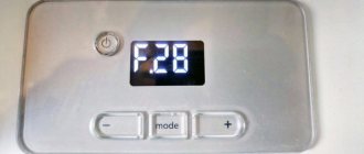
- F28. Check the presence of gas in the line. Clean the ionization electrode using fine sandpaper. Check the condition of the boiler grounding circuit. If all these measures do not give a positive result, look for the reason in the boiler’s electronic board. Most often you have to change it.
- F62. Gas valve malfunction. The device requires maintenance, cleaning and lubrication. There may also be problems with the electronic control board.
- F75. Problems with the pressure sensor. Check the total pressure in the system. Inspect the condition of the pump. Bleed the air in the radiators using a Mayevsky tap.
It is inappropriate to provide a complete list of problems and ways to eliminate them, since the very name of the error most often contains a hint on how to fix it. The predominant type of solution to the problem is to replace the unreliable element.
How to replace a faulty pressure switch
Replacing a pressure switch is a simple, non-labor-intensive, but at the same time fairly quick procedure. To successfully dismantle the faulty part, you must perform the following manipulations:
- Disconnect the equipment from the power supply;
- Press the upper latches and pull the pressure switch towards you;
- Disconnect all connected pipes from the faulty pressure switch.
After dismantling the unsuitable pressure switch, you need to purchase a new part and begin installing it. It is sold both in regular construction stores and on online markets. The average cost of such a spare part for repairing a Buderus boiler model Logamax U072 is 2500-4500 Russian rubles.
Types of descaling
Cleaning boilers from scale can be done in two ways:
- dismountable when its quantity has reached critical volumes that cannot be removed in any other way, and further operation of the device is also impossible;
- non-removable, which allows you to prevent the appearance of deposits on the internal walls of the case in advance, as well as get rid of them, provided that effective cleaning means are used.
Collapsible view
The dismountable method is the most effective, but labor-intensive. It allows you not only to assess the current condition of the boiler, but also to completely get rid of scale in any suitable way: mechanical or chemical.
A step-by-step analysis of the design is performed as follows:
We study the disassembly instructions, if they are offered by the manufacturer, or the device diagram. We select the necessary tools. We prepare cleaning products and consumables for maintenance. Disconnect the boiler from the power supply and wait until it cools down to room temperature. We close the valves on the inlet and outlet pipes of the heating circuit and drain the water from the boiler. We remove the protective casing by unscrewing the bolts in all places where it is attached.
In this case, it is important to control the efforts so as not to break the thread. Remove the top cover and gain access to the inner container. We dismantle the heating element and heat exchanger (if provided for by the design).
The disadvantages of this method are: inapplicability for non-dismountable welded sealed structures, the likelihood of incorrect assembly or damage to the heat-resistant coating.
Non-separable view
The non-dismountable method is used to reduce and eliminate scale formation on your own without the likelihood of serious consequences for the operation of the equipment. Its advantage is that there is no need to involve specialists. In some cases, to implement it, you do not need to turn off the boiler and then start it again.
This type of scale control has a number of disadvantages:
- cleaning efficiency can be assessed only by indirect signs: stabilization of temperature indicators, uniformity of heating, etc.;
- inability to control how much scale remains in the boilers and whether further removal is required;
- the difficulty of selecting the most effective product due to the unknown chemical composition of scale;
- instability of the boiler during cleaning.
What determines reliability and safety during operation?
There are certain factors on which the serviceability of gas boilers depends:
· Pressure surges in the heating system are caused by a lack of air in the expansion tank. In rare cases, the nipple may fail.
·Deposition of scale in heat exchangers, which occurs due to the hardness of the coolant, regular replenishment and low circulation of the coolant.
·No draft in the chimney channel and reverse draft effect in devices with forced smoke removal. In a coaxial chimney, blockage occurs due to improper design of the chimney or its blockage.
·Clogged, dirty and dusty burner and primary heat exchanger. May occur due to the use of boilers in damp and dusty rooms. And also where there is no or lack of air, which is necessary for combustion.
·Exit of the operating state of temperature sensors. Occurs due to water activity and poor-quality production of the sensors themselves. Occasionally it can happen due to overvoltage in the circuit of gas boilers of any type.
Diagnostic procedure for a turbocharged boiler
In a boiler that is equipped with a fan to remove combustion products, ensuring safe operation is somewhat more difficult. The draft is checked by an external device - a pneumatic relay. A device for measuring air flow (Venturi device or pitot tube) is also installed in the exhaust pipe, which is connected to the pneumatic relay through plastic tubes. That is, in this case, the principle of draft control is as follows: if the air flow created by the fan in the exhaust duct is greater than the minimum value to which the pneumatic relay is set, then the relay contacts close and the board gives a signal to ignite; if the air flow is less (draft is not sufficient) - the contacts open and the boiler operation will be stopped.
That is, in a typical smoke removal scheme for such a boiler there will be:
- inlet pipe
- fan
- control devices
- exhaust pipe
The inlet pipe is a pipe through which air enters the combustion chamber (it is closed in a turbocharged boiler). If, for example, the head of the pipe is covered with frost in winter, there will be no inflow, while the fan is characteristically quieter and the boiler will not start. Provided that everything is in order with the exhaust pipe and there are no other problems, if you open the combustion chamber, the boiler will start in normal mode.
The operation of the fan can be assessed visually (the blades are visible without dismantling). If the fan does not start when the boiler is turned on, then in most cases either there is no signal coming from the board (the board is faulty), or the fan itself is faulty. Damaged wiring does occasionally occur, but is rare. Service workers check the operation of the fan by directly applying voltage to it. If the fan operates, diagnostics and repair of the control board will most likely be required.
If the fan turns on and air flows normally into the combustion chamber, but the boiler does not start due to a smoke removal error, you need to check whether the pneumatic relay operates. You can check that the relay is activated visually (the relay makes a characteristic click) or, even better, with a tester - check the closure of the contacts in the wiring, because the relay may operate, but for some reason the signal does not reach the control board.
If the pneumatic relay does not operate, you need to make sure that there is no contamination or condensation in the supply pipes and that they are not damaged. As an option, you can independently create a vacuum in the supply tube and make sure that the relay operates. If it does not work, it is likely that it is faulty and must be replaced (in most cases they are not dismountable and cannot be repaired).
If the relay is forcibly activated, but normally, when starting the boiler it is not, then the Venturi (or Pitot) device should be inspected for damage or contamination. The slightest deformation or contamination can lead to malfunction.
Since the Venturi device is located in the exhaust pipe, it could be deformed by the high temperature of the exhaust gases.
Problems with the exhaust pipeline may be the same as with the intake pipeline, but you can, perhaps, verify that there is no blockage only visually or by measuring the actual vacuum with a device through specially provided control holes.
The air flow control device is installed inside the exhaust pipe. There is a possibility of heat damage (tube deformation) or contamination.
Some modern boilers can be equipped with fans with adjustable rotation speed, which is set in the settings depending on the type of chimney used and its length (for example, in some Buderus and Ariston models). Therefore, it would be a good idea to study the operating instructions for the equipment, since in practice there were cases when incorrect board settings were the source of the problem.
This article describes the most common and obvious causes of gas boiler malfunctions associated with the removal of combustion products. Different boilers can be equipped with different control schemes - we have looked at the most popular ones.
Please also note that it is unacceptable to disable control devices - all of them are provided for the safe operation of the equipment. If there is a problem, it needs to be fixed!
Positive qualities of the device
Products of this type are produced by the German company of the same name, which began its activities back in 1731 with the production of cast iron for its subsequent processing. At the end of the 19th century, the company began producing sectional boilers for heating systems. Such a long period of existence indicates the seriousness of intentions in the field of thermal technology.
If we talk about the advantages of devices for heating coolant, then first of all we should highlight the most basic of them.
- A long period of operation is ensured by the design itself, which assumes low tension in the base unit.
- The high efficiency of the units makes it possible to organize the most efficient heating systems for homes and technical premises.
- The high quality of the equipment is explained by the accumulated experience in the field of heating devices.
- Due to the wide range, you can choose the right products for a specific situation without much difficulty.
- The price of products varies in a fairly decent range, due to which the number of consumers is large.
- A high level of safety makes it possible to avoid situations that could lead to a fire.
- Due to the ease of installation, all work can be done with your own hands, thereby saving financial resources.
- Long-lasting combustion is achieved due to the design features of the devices.
This is how the boiler looks in a modern interior.
Reasons why the boiler does not turn on
If the heating equipment does not light up at all, the reasons include the following factors:
- the ignition system has failed;
- the gas supply is stopped or the tap on the pipe supplying it is closed;
- too low or high gas pressure inside the pipe;
- The burner nozzle is clogged.
If it doesn't light up the first time
Failures of a gas heating unit, in which case they light up immediately, are caused by various factors. External:
- too low gas pressure level in the main pipeline;
- problem with the functioning of the chimney;
- voltage fluctuations;
- draft or low temperature inside the building where the boiler is located.
Internal ones include failure of electronics, pump, heat exchanger.
If the unit goes out and then does not immediately light up, the cause of this phenomenon may be a lack of ventilation in the room. This often happens with heating devices “Proterm”, “Navien”, etc., in which the combustion chamber is open. They take combustion air from the room.
Other faults
When the pressure in the line drops, the dual-circuit devices “AOGV” or “Vailant”, for example, are switched off. This also happens when the fuel supply fluctuates. If the igniter is incorrectly adjusted, the protection is triggered and the boiler stops working.
To determine other faults, knowledge of the device that requires repair is required. Each model has its own distinctive features. But more often than not, components, sensors or circulation pumps break down for all brands. If such a pump fails, the burner will not turn on and the boiler will not be able to supply hot water and heating. It happens that the pump hums, but there is no work. It's quite possible it's jammed.
Sometimes the whole house can hear how loud and hard the boiler is working. This is most often caused by a large amount of scale in the heat exchanger. This factor often leads to overheating of the heat exchanger.
Injectors can also make a whistling sound. This happens when the boiler is ignited. A whistle indicates the presence of air in the gas pipeline. To eliminate the whistling, it is enough to release the air.
If water or condensation gets on the main board, irreparable damage occurs inside it. If the cause is moisture, streaks are visible on the board.
Attention! For long service life of gas equipment, the board must be protected from water leaks and steam ingress
Advantages and disadvantages
The opinions of the craftsmen and service personnel of service centers are clearly positive, even taking into account comparisons with other manufacturers and brands. Buderus boilers can and do operate continuously and without problems. Those who live in houses heated by Buderus boilers with professional service or, at least, in accordance with the manufacturer’s detailed instructions, simply do not want to share their experience; they already live peacefully in a warm house without any complaints about the heating equipment.
The stumbling block is the initial setup and commissioning of the boiler. It is really not simple and requires attention to detail. If a cast iron boiler is installed, connected and heated without detailed settings, then problems will not keep you waiting. These include clogged grates that need to be cleaned every hour. Poorly burnt coal and smoldering firewood lead to a decrease in coolant temperature.
If you treat the first launch responsibly, then there will be no problems. Long-burning boilers operate for 10-12 hours on one load and perfectly maintain the set temperature. It is enough to first set the settings in accordance with the task and adjust the few boiler options.
