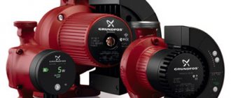
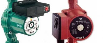
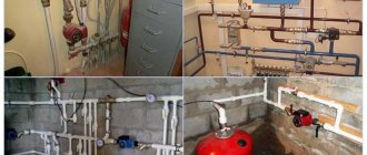
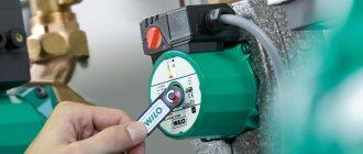
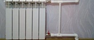
A circulation pump is a unit that performs the function of forced circulation of coolant in closed and open heating systems. The use of this unit accelerates the flow rate of water in heating radiators, due to which the air in the rooms is heated faster and more evenly.
How the unit works
The principle of operation of the circulation unit is very similar to the operation of a drainage pump. If this device is installed in a heating system, it will cause movement of the coolant by capturing liquid on one side and pumping it into the pipeline on the other side
The principle of operation of the circulation unit is very similar to the operation of a drainage pump. If this device is installed in a heating system, it will cause the movement of the coolant by capturing liquid on one side and pumping it into the pipeline on the other side. All this happens due to the centrifugal force, which is formed during the rotation of the wheel with blades. During operation of the device, the pressure in the expansion tank does not change. If it is necessary to increase the coolant level in the heating system, install a booster pump. The circulation unit only helps water overcome the resistance force.
The device installation diagram looks like this:
- A circulation pump is installed on the pipeline with hot water coming from the heater.
- A bypass valve is installed on the section of the line between the pumping equipment and the heater.
- The pipeline between the bypass valve and the circulation pump is connected by a bypass to the return pipeline.
This installation scheme involves the release of coolant from the device only if the unit is filled with water. To keep the liquid in the wheel for a long time, a receiver equipped with a check valve is built at the end of the pipeline.
Circulation pumps used for domestic purposes can develop a coolant speed of up to 2 m/s, and units used in the industrial field accelerate the coolant up to 8 m/s.
It’s worth knowing: any type of circulation pump operates from the mains. This is quite economical equipment, since the motor power for large industrial pumps is 0.3 kW, and for household appliances it is only 85 W.
Where to install
There are different opinions among experts regarding the installation of the unit in the system. Some suggest installing the pump on the supply pipeline, others on the return line.
In a home system, the temperature rarely rises above 70 °C, and the liquid does not heat up more than 90 °C. Therefore, the unit can be embedded in both the supply and return pipelines, while the difference in statistical fluid pressures between them is not significant, but it is better to focus on the second option. If there are two separate branches in the heating system, then it makes sense to install a separate device on each.
The pump must be installed immediately after the boiler, before the first branch in the circuit. Then it will be possible to set the required thermal conditions in each part of the house.
Forced circulation
In houses with a large area, air pockets may form in the system, which leads to disruption of circulation, overheating of the coolant in the boiler and damage. Therefore, a pump is installed in the return pipe before entering the boiler heat exchanger, which carries out forced circulation. This allows you to maintain the desired fluid speed and pressure.
The coolant often contains mechanical impurities that can damage the engine or cause the impeller to jam, so a dirt filter is installed in front of the device. Ball valves installed on both sides of the device allow you to repair or replace the unit without draining the liquid from the system.
Natural circulation
The process got its name based on the laws of physics. Thanks to the strictly maintained slope of the supply and return pipes, the heated liquid rises to the top point of the system, then, as it cools, it falls down, returning to the boiler. When operating in this mode, heat transfer will be low, in addition, a power outage is possible, so a pump is installed into the system. This gives high heating efficiency and reliability.
Additionally, a bypass line for the pump is installed - a jumper, which makes the system operational when the boiler is turned off. A ball shut-off valve is installed in the jumper. It opens when the power goes out or the appliance fails. The tap leading to the pump is closed, and the system begins to operate on the principle of gravity.
Where circulation units should not be installed
It is not advisable to install circulation pumps on the supply line. There are cases when air accumulates in the upper part of the boiler, the device cannot draw it in, as a result, a vacuum is formed, which leads to boiling of the coolant.
The resulting steam-water mixture begins to move into the system. The pump stops because it can only pump water. If measures are not taken in time, an explosion is possible.
Choosing a place
When installing such a unit, it is necessary to choose a method for inserting it, taking into account the fact that in the future the device will need to be serviced. In addition to this requirement, there are other points that affect the choice of installation location.
Previously, it was cut into the return line so that the working area was washed with already cooled water, and thereby extended the life of the device. Nowadays, manufacturers produce pumps with parts and assemblies made of materials that are not afraid of exposure to hot water. Therefore, they can be installed not only in the return pipeline, but also in the supply pipeline.
You need to decide where exactly you will embed the device.
To increase the pressure of the coolant, it should be installed on the section of the water supply pipe, placing it closer to the entrance to the expansion tank system. This will ensure high temperatures are maintained.
Before installing it on a bypass (jumper, section of pipe between the direct and return coolant supply), you need to check whether the device can withstand strong pressure of hot water.
If there is a membrane tank, the bypass pump is cut into the return pipeline, preferably closer to the expansion tank. When access to the device is difficult, it can be installed on the supply pipeline, and a check valve can also be installed there.
What to do if the device hums but does not turn?
This problem is faced by those pump owners who do not often use the devices and ignore the need to maintain the heating system. To fix the problem you will need:
- Turn off the power to the unit;
- Drain the coolant from the pump and adjacent pipes;
- Remove the screws that secure the motor housing;
- Remove the engine along with the rotor;
- Turn the rotor with a screwdriver, resting against the notch.
If the cause of the breakdown lies in foreign objects getting into the device, then you need to act in the following order:
- Turn off the power to the pump;
- Drain the water;
- Unscrew the screws holding the motor housing;
- Find and remove foreign objects;
- Install a strainer on the inlet pipe.
Once the repair is complete, the device will start working again. The filtration element will protect the device from solid particles, which will significantly extend the service life of the entire system.
Main varieties
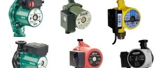
All circulation pumps for heating systems are divided into two design types: devices with a “dry” rotor and circulation pumps with a “wet” rotor.
In circulation pumps of the first type, as is already clear from their name, the rotor does not come into contact with the liquid working medium - the coolant. The impeller of such pumps is separated from the rotor and stator by sealing steel rings, which are pressed against each other using a special spring that compensates for the wear of these elements. The tightness of this sealing unit during pump operation is ensured by a thin layer of water between the steel rings, formed due to the difference between the pressures in the heating system and in the external environment.
Circulation pumps for heating with a dry rotor are characterized by fairly high efficiency (89%) and productivity, but hydraulic machines of this type also have disadvantages, including loud noise during operation and difficulty in operation, maintenance and repair. As a rule, pumps of this type are equipped with heating systems for industrial purposes; they are used quite rarely in domestic heating systems.
Single-stage circulation pump with dry rotor
A circulation pump for heating systems, equipped with a “wet” type rotor, is a device whose impeller and rotor are in constant contact with the coolant. The working environment in which the rotor and impeller rotate acts as a lubricant and coolant. The stator and rotor of pumps of this type are insulated from each other using a special glass made of stainless steel. Such a glass, inside of which the rotor and impeller are located rotating in the coolant medium, protects the stator winding, which is under voltage, from contact with the working fluid.
The efficiency of pumps of this type is quite low and is only 55%, but the technical capabilities of such a device are quite sufficient to ensure the circulation of coolant in heating systems of houses that are not too large. If we talk about the advantages of circulation pumps with a “wet” rotor, then they include the minimum amount of noise produced during operation of such devices, high reliability, ease of operation, maintenance and repair.
Wet type circulation pump
Design features
The pump is designed simply: 2 parallel disks are connected to each other by curved blades and form an impeller. One of them has a hole for coolant flow, and the other has clamps to fix the structure on the impeller motor shaft.
Before using a pump, it is better to first become familiar with its design.
Design elements:
- The body is made of various materials - it can be stainless steel or non-ferrous alloys;
- Rotor;
- Rotor shaft;
- Rotating rotor;
- Impellers or impeller;
- Electric motor.
To direct the liquid in the desired direction and create kinetic energy and pressure, there is a hole in the shape of a spiral (in section). In a fixed wheel, the coolant lubricates and cools the rotor shaft. The stator of the electric motor is placed under voltage, so it is divided by a glass, which is equipped with stainless steel or carbon material. The rotor of the unit is mounted on ceramic bearings. Such pumps are used for heating when recirculating coolant with a constant or slightly variable flow rate.
Power connection
The circulation pumps operate from a 220 V network. The connection is standard; a separate power supply line with a circuit breaker is desirable. The connection requires three wires - phase, neutral and ground.
Circulation pump electrical connection diagram
The connection to the network itself can be organized using a three-pin socket and plug. This connection method is used if the pump comes with a connected power wire. It can also be connected via a terminal block or directly with a cable to the terminals.
The terminals are located under a plastic cover. We remove it by unscrewing several bolts and find three connectors. They are usually labeled (the pictograms are N - neutral wire, L - phase, and “ground” has an international designation), so it’s hard to make a mistake.
Where to connect the power cable
Since the entire system depends on the performance of the circulation pump, it makes sense to make a backup power supply - install a stabilizer with connected batteries. With such a power supply system, everything will work for several days, since the pump itself and the boiler automation “pulls” electricity to a maximum of 250-300 W. But when organizing, you need to calculate everything and select the battery capacity. The disadvantage of such a system is the need to ensure that the batteries do not discharge.
How to connect a circulator to electricity through a stabilizer
Hello. My situation, a 25 x 60 pump is located immediately after a 6 kW electric boiler, then the line from a 40 mm pipe goes to the bathhouse (there are three steel radiators) and returns to the boiler; after the pump, a branch goes up, then 4 m, down, rings a house of 50 sq. m. m. through the kitchen, then through the bedroom, where it doubles, then the hall, where it triples and flows into the boiler return; in the bathhouse there is a branch 40 mm up, it leaves the bathhouse and enters the 2nd floor of a house of 40 sq. m. m. (there are two cast-iron radiators) and returns to the bathhouse in the return line; there was no heat on the second floor; the idea of installing a second pump in the bathhouse for supply after the branch; the total length of the pipeline is 125 m. How correct is the solution?
The idea is correct - the route is too long for one pump.
What indicators need to be taken into account when choosing
We begin the selection of a circulation pump for hot water supply with indicators of its performance and pressure.
- Productivity is the volume of water (or other liquid) that the pump pumps in a certain unit of time (cubic meters per hour or liters per minute);
- Pressure is the pressure created by the pump (measured in Bars, Pascals or lift height in meters).
In addition, we also take into account the technical characteristics:
- Power of the installed electric motor in W;
- Type of control (temperature sensor or timer).
Capacity depends on the length of the pipe system. If the total length of the pipeline is 40-50 meters (an average house), then a pump with a capacity of 0.2 to 0.6 cubic meters per hour will be sufficient.
The motor power should also be low so as not to waste electricity. On average, the figure for a small private house, cottage, cottage is from 5 to 10 W. For large houses with several floors, 20 W of power is sufficient.
The choice of a circulation pump for hot water supply according to the characteristics of its pressure (lift height) will be correct if one is guided by the following rules:
- For a one-story house, where the pipeline is single-level, we take a pressure with a height of water rising from half a meter to 0.8 meters;
- For a building with several floors, add the height of the water supply pipes;
- Plus - we create a certain pressure reserve, 10-20 percent.
Carrying out work
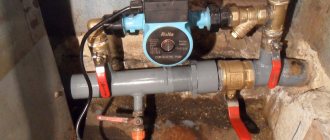
Correct installation of the pump in the heating system of a private home requires performing work following certain installation rules. One of them is an insert on both sides of the circulation unit of ball valves. They may be needed later when dismantling the pump and servicing the system.
It is necessary to install a filter for additional protection of the device.
Typically, the water quality leaves much to be desired, and particles that come across can damage the components of the unit.
Mount a valve on top of the bypass - it doesn’t matter whether it is manual or automatic. It is needed to bleed air pockets that periodically form in the system.
The terminals should be directed straight up. The device itself, if it is a wet type, must be mounted horizontally. If this is not done, only part of it will be washed with water, and as a result, the working surface will be damaged. In this case, the presence of a pump in the heating circuit is useless.
The circulation unit and mountings must be positioned in the heating circuit naturally, in the correct sequence.
Before starting work, drain the coolant from the system. If you haven’t cleaned it for a long time, clean it by rinsing it several times.
On the side of the main pipe, in accordance with the diagram, install a bypass - a U-shaped piece of pipe with a pump built into its middle and ball valves on the sides. In this case, it is necessary to take into account the direction of water movement (it is marked with an arrow on the body of the circulation device).
Each fastener and connection must be treated with sealant to prevent leakage and make the entire structure more efficient.
After securing the bypass, fill the heating circuit with water and check its ability to function normally. If errors or malfunctions are discovered, they must be corrected immediately.
Control method
Maintaining the circulation of hot liquid at all times is acceptable, although this is not always economically justified. Many will agree that there is not always a need for such water, so there is no need for the pump to work non-stop. If the pipes are routed correctly and thermal insulation is installed, the liquid will not immediately cool down. As far as monetary costs are concerned, this will not affect them since recirculation pumps are inexpensive to maintain.
The control method can be by timer, that is, schedule, and by temperature sensors.
How circulation pumps work
The circulation pump is a centrifugal type of device. The mechanism of the unit is enclosed in a housing, which can be made of any stainless metal or impact-resistant plastic. The body consists of two halves. On one side there is an electric motor, on the other side there is a chamber for pumping coolant. The chamber cavities are equipped with outlets. They can be threaded or flanged.
The main working unit is an impeller mounted on a ceramic rotor. Rotating from the drive - an electric motor, it creates a directed flow of working fluid in the heating network pipeline. All technical characteristics of the device depend on the design, dimensions, external data of the impeller, and its rotation speed.
Through outlets, the pump is connected to the water main. On one side and the other, the unit is attached to the pipes via a quick-release coupling. Typically this connection is a fitting with a union nut. The flange connection is secured with four bolts with nuts, flat washers and spring washers. A sealing gasket made of paronite or heat-resistant rubber is installed between the flanges.
ATTENTION! The connector where the two halves connect has two holes for drainage. Through them, condensate that accumulates in the stator half of the electric motor is removed
It is strictly prohibited to cover drainage holes! When installing heating equipment, it is also necessary to remember that the impeller must be located strictly horizontally as part of the heating system. The pump itself can be installed in any position of the pipeline relative to the horizontal axis. It can be located on a horizontal section of the pipeline, vertical, at any angle to the horizon. But the impeller axis must be oriented strictly in the horizontal plane!
