- ensure optimal temperature inside the building and
- reduce heating costs.
In our review of heating system control units you will learn:
- When is it advisable to install a weather control unit - examples and calculations
- How does the heating control unit work?
- The main advantages of installing an automated heating control unit
- How to install an automated heating system control unit
- Effective use of automated metering units
- conclusions
Automated heating control unit
Regulation of heat supply in an apartment building
The most common way to provide thermal energy to apartment buildings is central heating. The coolant is supplied through heating mains from central boiler houses or thermal power plants. The heated liquid is received by the heating point .
It performs primary heat metering, ensures supply regulation, and distributes it to consumers. There are other options for heating apartments. Among the most common: individual heating of an apartment building, heating of a separate apartment. Each scheme has advantages and disadvantages; the choice of the most convenient one depends on a number of factors: the proximity of highways, their condition, the feasibility of using energy from remote boiler houses. In any case, the design of new communications and the reconstruction of old networks should include the development of mechanisms for regulating the supply of heat to apartment buildings. This is not so much a question of comfort as of saving energy resources.
Automation of the process of regulating the heat supply of MKD
The existing system of transportation and distribution of thermal energy is far from ideal. Its imperfection is especially acute during the off-season. It often happens that the weather outside is consistently warm, and the radiators stubbornly heat the already warm rooms. This situation is due to the fact that the only link in the chain of enterprises, communications and coolant supply devices that has the ability to influence the heat supply process is the boiler house or thermal power plant. But even they do not have the possibility of flexible regulation; they do not have mechanisms that allow them to instantly respond to weather changes.
The ideal option for regulating the heat supply in an apartment building would be a project in which, when implemented, it becomes possible to regulate the temperature of each room separately. This solution allows for individual metering of heat supply, which in turn allows residents not to pay for heat that simply escapes through open vents.
Individual metering of heat supply allows the consumer to independently regulate the amount of thermal energy consumed . This can be achieved by setting the temperature of rooms that are not in use lower, raising it as needed.
Heat supply can be regulated by turning off the taps on the radiators. In addition, you can entrust the regulation process to automation. Modern industry offers various devices that allow you to regulate the room temperature. The most common of them are radiator thermostats. These are devices consisting of a thermostatic head and a valve. The sensor measures the room temperature and controls the valve. Depending on the preliminary settings, the valve increases or decreases the flow of coolant, adjusting the heating level.
Thanks to the possibility of precise adjustment, this device allows you to regulate the microclimate inside the building, maintain a comfortable atmosphere, and save energy. There are different types of radiator thermostats. Most of them allow you to set the temperature value that the owner of the room wants to achieve. More complex models exist. Some of them allow you to set the temperature for different times of the day; for example, they can limit the heat supply during the day when there is no one in the apartment, and in the late afternoon they can warm the room to a comfortable level.
Connection diagrams
The elevator unit can be used in systems with various specific features - single-pipe, autonomous or other heat supply lines. The principles of coolant supply and flow parameters do not always allow for a constant and stable output result. To organize normal heat supply to apartments or adjust the flow parameters coming from the main network, various connection schemes for elevator units are used. All of them require additional equipment, sometimes in quite large quantities, but the result achieved as a result of this compensates for the costs incurred. Let's look at the existing connection diagrams:
With water flow regulator
Water consumption is the main factor that makes it possible to adjust the heating mode of the premises. Changes in flow cause temperature fluctuations in living rooms, which is unacceptable. The issue is resolved by installing a regulator in front of the mixing unit, which ensures constant water flow and stabilizes the thermal regime.
Diagram of an elevator mixing unit with a flow regulator: 1 - supply line of the heating network; 2 - return line of the heating network; 3 - elevator; 4 - flow regulator; 5 - local heating system
This solution becomes especially important in single-pipe systems, where there is a load in the form of hot water supply, which destabilizes the flow of hot water and creates significant fluctuations during active water withdrawal (morning and evening hours, holidays and weekends). At the same time, this scheme is not able to correct the situation when the temperature of the coolant in the main line changes, which is its drawback, although not too significant. A drop in coolant temperature in the supply pipelines means an accident at a thermal power plant or other heating point, and this rarely happens.
With regulating nozzle
The connection diagram of the elevator unit with the ability to adjust the nozzle capacity allows you to quickly respond to changes in coolant parameters in the main line.
Diagram of an elevator unit with a regulating needle: 1 - supply line of the heating network; 2 - return line of the heating network; 3 - elevator; 5 - local heating system; 6 - regulator with a needle pushed into the elevator nozzle
At the same time, manual adjustment is ineffective, since for this you need to constantly approach the elevator, which is usually located in the basement. The greatest efficiency of a system with an adjustable nozzle is achieved with complete automation of the process, using temperature and pressure sensors that send a signal to the elevator servo drive. This scheme allows you to gain additional opportunities when setting the operating mode, but the need for it does not always arise, but only in overloaded or unstable systems with possible fluctuations in coolant temperature.
Diagram of an elevator unit using temperature and pressure sensors that send a signal to the elevator servo drive
The disadvantages of such schemes include the need to initially ensure high pressure in the system, since adjustment is possible only within the limits of the flow parameters in the line. In addition, loads on the mechanics, in particular on the nozzle and needle, create the need for constant monitoring and timely replacement of failed elements.
With control pump
Such schemes are used in the absence of sufficient pressure in the supply pipelines for the operation of the elevator.
Diagram of an elevator unit with a correction pump: 1 - supply line of the heating network; 2 - return line of the heating network; 3 - elevator; 4 - flow regulator; 5 - local heating system; 7 — temperature controller; 8 - mixing pump
An increase in pressure makes it possible to use an elevator unit in the autonomous heating networks of a private house and allows for circulation of the coolant when the pressure in the main disappears. The pump is installed in front of the elevator or on the jumper between the forward and return pipelines before entering the elevator. To ensure normal operation, a temperature controller must be used in addition to the pump, and a power supply must be connected.
Heat regulation in individual heating systems
The concept of individual heat supply implies that the boiler room is located directly in the apartment building. For its placement, basements and ground floors are used, and modular boiler rooms are also used, which are placed on the roofs of buildings.
The implementation of individual heating of apartment buildings is quite an expensive project. It requires a significant investment, however, it provides an opportunity to save money. The length of the lines for individual heat supply is limited by the size of the building, which entails small heat losses during transportation. In addition, easy access to boiler room equipment allows you to more effectively regulate the heat supply to an apartment building.
A separate case of individual heat supply is the installation of autonomous heating in the apartments of an apartment building. For this purpose, boilers are used, most often gas boilers, which are an integral part of a closed heating system. This solution makes it easy to automate the process by using devices that can regulate the temperature of a single room.
Effective use of automated metering units
The use of ACU is most effective:
- in large buildings with significant heat consumption,
- in houses connected to city heating networks,
- in buildings with insufficient pressure drop in the central heating system and where the installation of central heating pumps is mandatory,
- in buildings with decentralized hot water supply and central heating.
Single-pipe heat supply option MKD
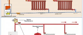
The simplest option for heating an apartment building is a single-pipe system. The coolant is supplied from the bottom up, it fills the radiators, gives off heat and moves to the next consumer. This system has a number of significant disadvantages. One of the main ones is significant heat loss during transportation. The last consumers in the chain receive a slightly heated liquid.
In addition, a single-pipe system makes it almost impossible to regulate the heat supply in an apartment building. It is not possible to install valves or automatic control devices on the supply pipelines, since a decrease in the flow rate within any of them will affect the entire system. You also need to remember about possible emergency situations. A single-pipe system does not allow the replacement of one of its components without completely draining the system. A minor breakdown can result in a stop in the heat supply to all consumers.
Heat supply and regulation with a two-pipe scheme
This option is more complex, but it allows you to significantly expand the capabilities of the mechanisms for regulating the heat supply to each consumer . The difference between the system is that the coolant that has given up part of the energy does not continue to move through the same pipe to the next consumer; it flows into the second pipe, the “return”. Thanks to this, the coolant has approximately the same temperature along the entire path, at each radiator.
It is this solution that makes it possible to regulate the heat supply in an apartment building using each individual radiator. You can regulate the temperature either manually using a valve or automatically using thermostats.
Regardless of how the heat supply is implemented, the system must include devices for automatic metering and regulation of heat supply in an apartment building. This makes it possible not only to provide housing with the heat necessary for life, but also to significantly save energy resources.
Weather control of heating in Izhevsk
Currently, many are thinking about how to automate housing and communal services so that it is possible to save thermal energy in apartment buildings or factories. It is the installation of a weather control system that will help accomplish this task. This installation allows not only to save the family budget, but also to save thermal energy, which is directly related to environmental protection. The system is installed in an ITP with weather regulation.
Installation of an automatic weather control system in the ITP of apartment buildings. Video.
The essence of installing a weather control system
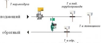
Weather regulation is a new, completely innovative step for housing and communal services. The essence of this installation is as follows: setting the required heating temperature depending on weather conditions. To do this, three sensors are installed - external, in the pipeline supplying coolant and return, which informs about the average temperature at the last batteries. They measure the temperature on the north side of the building and the temperature of the water in the pipes. The controller located in the structure makes calculations regarding the required temperature delta and then itself adjusts the speed and volume of the coolant.
There are many advantages to this design. In addition to those listed above, there is also the so-called technical stability. That is, the installation has established itself as a system capable of uninterrupted operation, even in winter, because has options for trouble-free installation of the pump group piping. Automatic weather control has undergone many tests by ATK LLC specialists, both in production conditions and on the basis of beta testing.
1.1.1. Design, operation of the Komos UZZH-R flow regulator and its technical characteristics
The figure shows a general view of the Komos UZZH-R regulator.
Symbols of elements:
1 - body; 2 - hydraulic cylinder; 3 - control piston; 4 - flanges; 5 - control piston; 6 - adjusting nut; 7 — rod; 8 - valve; 9 — valve seat; 10 - bottom; 11 — inlet pipe; 12 — outlet pipe; 13 — limiter of movement of the adjusting nut; 14 — sealing ring.
Inside the housing (1) there is a control hydraulic cylinder (2), in which a heat-sensitive liquid is placed. This liquid has a linear law of increasing volume as its temperature increases and decreasing volume as its temperature decreases.
First, the regulator is adjusted to the desired coolant flow rate, at which the air temperature in the interior of the building (with the ambient temperature values available during adjustment of the regulator, as well as the temperatures in the forward and return pipelines of the heating system) complies with SanPin standards (SanPiN is currently in effect 2.1.2.2645-10). Then, during the entire heating period, the regulator operates automatically.
If the coolant entering the regulator through the inlet pipe (11) has a temperature higher than the value that existed at the time of adjustment, then, by transferring its heat to the heat-sensitive liquid through the walls of the hydraulic cylinder (2), it causes an increase in the volume of the heat-sensitive liquid. In this case, the heat-sensitive liquid presses on the piston (5) and through the rod (7) brings the valve (8) closer to the seat (9). This leads to a decrease in coolant flow into the regulator and, accordingly, to a decrease in coolant flow through the heating system.
And vice versa: if the coolant entering the regulator through the inlet pipe (11) has a temperature lower than the value that existed at the time of adjustment, then the heat-sensitive liquid will compress, which will lead to the valve (8) moving away from the seat (9) and an increase in coolant flow through the system .
Thus, the Komos UZZH-R regulator automatically regulates the amount of coolant and, accordingly, thermal energy passing through the heating system of the building.
What is included in the installation of “weather control of heating”
Of course, in order to receive a service that provides weather control of heating in apartment buildings , guaranteeing both warmth and savings for residents, it will be necessary to install a number of necessary components, without which the system simply cannot function properly. Thus, to obtain a weather control system, it is necessary to install several of the following structures:
- Controller
- Circulation pump;
- Control valve with electric wire or control elevator;
- Pump control panel;
- Temperature sensors, temperature sensors;
- The “small” parts required, such as a coupling, a series of flanges, several taps and valves, wires, filters, and so on.
Installation of automatic weather control systems for heating is carried out according to a developed and agreed upon project. This system saves you not only your budget, but also guarantees a comfortable climate in hot spring and the necessary warmth in cold weather. The price for installing an automatic weather control unit is determined by an engineer on site or in the design and estimate documentation from RUR 54,400. up to 480,000 rub.
Manual adjustment instead of automatic weather adjustment at the substation. Video.
Why ITP with weather regulation?
IHP with weather control can be supplied as part of block heating units or existing individual units can be modernized with the introduction of automatic weather control systems.
It is known that heating systems of apartment buildings are designed for high-quality regulation, that is, when the temperature outside changes, the temperature of the coolant changes. When determining the water temperature in the heating main, resource supply organizations rely on the temperature graph. The lower the temperature outside, the higher the temperature of the coolant in the heating devices. The most common heating schedule in Russia is 95/70 – 41/35. However, the high inertia of the heat supply system and the equalization of all houses to a single coolant temperature makes it necessary to equip ITP with weather control.
Also, do not forget that the coolant temperature cannot drop below 70 °C, because According to sanitary standards, hot water supply should not be lower than 60-65 °C. Such a restriction in the spring and autumn leads to the “flooding” of apartment buildings.
Based on the above reasons, it is clear that it is necessary to install an automatic weather control unit . Invite engineers to an initial inspection of the ITP, in order to establish the possibility of installing automatic weather control on the control unit. The heating engineer’s visit is free and does not oblige you to anything.
Heat supply organizations for approval of the installation of an automatic weather control unit for ITP in Izhevsk and the Udmurt Republic:
"Udmurtsky" PJSC "T Plus", Izhevsk
LLC "Udmurt Utility Systems" Izhevsk
LLC "District Heat Supply Company", Izhevsk
OJSC "Volzhskaya TGK" Izhevsk
JSC "Votkinsk plant" Votkinsk
Municipal Unitary Enterprise "Communal Heating Networks" Votkinsk
Archive of numbers
Issues for 2009:
№1 (1), №2 (2), №3 (3), №4 (4), №5 (5),
Issues for 2010:
№1 (6), №2 (7), №3 (8), №4 (9), №5 (10), №6 (11), №7 (12), №8 (13),
Issues for 2011:
№1 (14), №2 (15), №3 (16), №4 (17), №5 (18), №6 (19),
Issues for 2012:
№1 (20), №2 (21), №3 (22), №4 (23), №5 (24), №6 (25),
Issues for 2013:
№1 (26), №2 (27), №3 (28), №4 (29), №5 (30), №6 (31),
Issues for 2014:
№1 (32), №2 (33), №3 (34), №4 (35), №5 (36), №6 (37),
Issues for 2015:
№1 (38),
№2 (39)
, №3 (40), №4 (41), №5 (42),
Issues for 2016:
№1 (43), №2 (44), №3 (45), №4 (46),
Issues for 2022:
№1 (47), №2 (48), №3 (49), №4 (50),
Issues for 2022:
№1 (51), №2 (52), №3 (53), №4 (54).
Installation of weather control heating systems
In order to implement in St. Petersburg the Federal Law of the Russian Federation of November 23, 2009 No. 261-FZ “ On energy saving and increasing energy efficiency and on introducing amendments to certain legislative acts of the Russian Federation” and Resolution of the Government of St. Petersburg No. 405 dated 04/28/2012 “On approval of the list of mandatory measures for energy saving and increasing energy efficiency in relation to the common property of owners of premises in an apartment building” LLC “SET” has developed and patented circuit solutions for the modernization of existing elevator units of residential and administrative buildings with additional equipment of their system automatic weather control (CAD) of heat consumption.
Installation of this unit eliminates excess heat consumption of buildings (“overheating”) at positive outdoor temperatures. At the same time, the uniformity of heating of all rooms inside the building is improved while the payment for thermal energy is reduced to 20%-30% for the heating season.
A feature of the modernization of heating points using the technology of SET LLC is that it allows you to preserve the existing ITP equipment, incl. elevator unit, which increases the reliability of the system, makes it energy-independent, and also allows you to convert the heating unit into an automated individual heating unit without the extra costs of purchasing factory modules.
In addition, all data on consumed and saved heat (including those expressed in monetary terms) can be viewed in real time on a computer or mobile phone through your personal account.
The cost of installation of an automatic weather control unit depends on the characteristics of the ITP and the needs of the Customer.
The turnkey turnkey automation period for ITP , including the development of design documentation, approval by the heat supply organization, construction, installation and commissioning works, and delivery of the facility to the heat supply organization is up to 90 calendar days .
When performing work, Danfoss equipment, Wilo pumps, and an automatic control unit for the elevator unit of our own production are used (certificate of compliance RU No. 0491159).
The technical solution of SET LLC has been patented, reviewed and approved by the Scientific and Technical Council in the field of housing and communal services of St. Petersburg under the Housing Committee of St. Petersburg, the technical council of JSC Heating Network of St. Petersburg, the technical council of the State Unitary Enterprise TEK SPB, and also agreed to application by the North-West Directorate of Rostechnadzor.
This technology has been successfully used in St. Petersburg , both in the housing stock and in state budgetary institutions since 2014, including when carrying out major repairs of apartment buildings. So, in 2017-2018. In the past year, our company has modernized more than 100 ITPs in buildings for various purposes in St. Petersburg and Moscow.
On September 25, 2018, SET LLC’s technology for modernizing existing elevator units with retrofitting them with an automatic weather control system with technological protection and remote monitoring was included by decision of the Expert Council in the federal Data Bank of Smart Cities Technologies (russiasmartcity.ru).
More information about ETS weather control units can be found here.
When is it advisable to install an ACU - examples and calculation of the payback period
Let's look at 3 examples of installing a metering unit and calculate the payback period for this event.
All examples are from real life and are based on energy surveys that we have carried out.
And so, we have three administrative buildings (offices):
- Building 1 with an area of 1300 m2
- Building 2 with an area of 4800 m2
- Building 3 with an area of 18,500 m2
All three buildings are located in Moscow.
Here are the main results of installing the heating system control unit:
| Area, m2 | Total heat consumption for the heating period before installing the ACU | Total heat consumption for the heating period after installing the ACU | Reducing heat consumption Gcal | Cost Gcal thousand rubles. (2018) | Savings during the heating period, thousand rubles. | |
| Building No. 1 | 1 300 | 340 | 266 | 74 | 2,0 | 148 |
| Building No. 2 | 4 800 | 550 | 418 | 132 | 2,0 | 264 |
| Building No. 3 | 18 500 | 4 400 | 3 720 | 680 | 2,0 | 1 360 |
As can be seen from the table, installing a heating control unit helped reduce heat consumption during the heating period by:
- Building No. 1 – 74 Gcal,
- Building No. 2 – 132 Gcal,
- Building No. 3 – 680 Gcal.
Such a significant difference in consumption reduction is mainly due to:
- size of buildings (area and number of storeys)
- number of operating hours,
- appointment.
The following table shows:
- heat savings during the heating period (based on the cost of 2 thousand rubles per Gcal)
- cost of installation and assembly of the heating control unit and
- payback period.
| Savings during the heating period, thousand rubles. | Cost of automatic control unit (equipment and installation) | Simple payback period years | |
| Building No. 1 | 148 | 1 556 | 10,5 |
| Building No. 2 | 264 | 1 856 | 7,0 |
| Building No. 3 | 1 360 | 2 000 | 1,5 |
The main conclusion that we can draw from calculating the payback period of an automated control system
It is advisable to install an automated heating control unit in buildings with significant consumption of thermal energy and in buildings with overheating.
In small buildings and buildings with low thermal energy consumption, an automated heating control unit will pay for itself for a very long time or may never pay off.
In small buildings, it is more advisable to inspect or install elevator units, as well as install a system of balancing valves on the main risers of the heating system.
Heating system control unit
Automatic heating control system in an apartment building
The adoption of Federal Law 261-FZ “On Energy Saving...” served as an impetus for the development and implementation of regional and municipal energy saving programs, the implementation of which is promptly monitored both by the state and by regional authorities.
Currently, work has been organized in the Chelyabinsk region in the field of energy saving and increasing energy efficiency. There is a regional target program “Energy saving and increasing energy efficiency” for 2014–2020, approved by Decree of the Government of the Chelyabinsk Region No. 346-P on October 22, 2013. One of the main directions of the program is reducing thermal energy consumption in buildings.
Significant heat savings in buildings are achieved by installing automatic control systems at heating points.
The installation of automation systems on the thermal inputs of buildings with weather control allows you to maintain optimal microclimate parameters in the premises, taking into account a number of factors: outside air temperature, heat emissions from equipment and people, the influence of solar radiation, wind direction and speed, orientation of the premises to the cardinal points, etc.
The system of automated weather control of thermal energy ensures a change in coolant flow depending on the real needs at each moment. At the same time, heat savings for the needs of consumers are achieved, which averages from 10 to 30%.
The control system includes the following equipment: temperature controllers, temperature sensors, control devices, which include shut-off and control valves, mixing and control valves and control hydraulic elevators. It is possible to use systems of various purposes and complexity: single- and double-circuit, with additional functions of pump control or accumulation and processing of statistical information about the progress of the regulation process. The equipment offered by manufacturers differs in operating principle, purpose and cost.
In the city of Magnitogorsk, Chelyabinsk region, all heating points of residential buildings being commissioned are equipped with automatic control systems for heat consumption. In this case, various automation schemes are used and equipment from different manufacturers is used.
To compare thermal energy savings, heat consumption was monitored and the operation of heating point automation systems was examined using the example of two adjacent 10-story, 3-section panel residential buildings, commissioned in 2013. The houses have the same layout, identical characteristics of the enclosing structures and estimated heat consumption volumes.
In the heating point of the first residential building, automatic regulation is provided using a dual-circuit temperature regulator RT-2010-00 (Eton Plant, Republic of Belarus). To regulate heat consumption in heating systems, regulating hydraulic elevators RG from the same manufacturer are used.
The residential building has a façade-by-facade control system for heating systems. For this purpose, the heating system of the building is divided into separate per-facade circulation rings, which are combined by jumpers into two per-facade heating systems F1 (western facade) and F2 (eastern facade). Both heating circuits are controlled independently of each other. The IHP is equipped with two regulating hydraulic elevators for façade-by-facade regulation of the flow rate of coolant supplied to the heating system depending on the outside air temperature.
Saving thermal energy with facade automatic control occurs through the use of heat gain from solar radiation and reducing excessive air exchange in apartments when there is wind.
The controller, together with the sensors and actuators (EG) connected to it, provides weather control of the temperature in the supply and return pipelines of the heating system, independent of the central heating networks. During operation, the controller periodically polls coolant temperature sensors and an outside air sensor, processes the information received and generates output control signals that command the actuator to open or close. Regulation is made from an outside temperature sensor depending on weather conditions and changes in heat load.
By implementing control actions that change the output cross-section of the working nozzle of the hydraulic elevator, there is a high-quality regulation of the parameters of the coolant and its economical consumption due to the use of return coolant by injection and the creation of the necessary water circulation in the heating system instead of a circulation pump.
In Fig. 1, 2 show graphs of changes in the temperatures of the outside air, supply and return coolant, as well as the actual and standard consumption of thermal energy for heating the residential building in question for the months of the heating period of 2014.
Rice. 1. Actual values of the average monthly temperatures of the external tn, supply T1 and return T2 coolant for the months of the heating period of 2014
Rice. 2. Heat consumption for heating a residential building, standard Qn and actual Qf for the months of the heating period of 2014
Rice. 3. Heat consumption for heating a residential building, standard Qn and actual Qf for January-April of the heating period 2013–2014.
The savings in thermal energy for heating needs in the residential building under consideration with an automated weather control system for the months of the heating period in 2014 amounted to 23.6%.
In order to determine the amount of heat savings depending on periods with different outside air temperatures, hourly readings of the heat meter per day were analyzed with an average daily tn equal to – 1.5 °C (12/23/2014) and – 17.6 °C (01/02/2015) ). Heat savings for heating needs per day with an average temperature of 1.5 °C amounted to 26.1%; per day with tn = – 17.6 C was 44.7%.
In the heating point of the second residential building, equipment for an automatic control system for thermal energy consumption was installed.
An electronic controller of the ECL Comfort series is used as a regulator. These controllers, based on the ratio of the readings of the coolant and outside air temperature sensors, as well as on a timer command, control, depending on the modification of the device, the control valves through which the coolant is supplied from the heating system.
The temperature of the coolant in the heating system of a residential building is regulated by changing the capacity of a two-way valve with an electric drive and mixing network water using a Grundfoss circulation pump. During operation, the controller periodically polls coolant temperature sensors and an outside air sensor, processes the information received and generates output control signals that give commands to the actuator. The control action from the controller changes the size of the flow area of the control valve.
In Fig. Figure 3 shows a graph of changes in actual and standard heat energy consumption for heating a residential building with an automatic control system from January to April of the heating period 2013–2014.
In accordance with the graph data in Fig. 3 savings of thermal energy for heating needs for the considered months of the heating period 2013–2014. is 21.5%.
Over the same period (from January to April 2014), the amount of heat saved in the previously considered residential building with the automatic control system “Eton Plant” was 20.7%.
A comparison of the results showed that in residential buildings with automatic weather control systems from different manufacturers, the thermal energy savings are approximately the same.
The residential buildings in question have hot water preparation and DHW flow regulators installed. The electronic unit used is the same. It processes the information received from the hot water temperature sensor and gives a command to the shut-off and control valve. By changing the flow area, the valve regulates the amount of coolant entering the heat exchanger of the hot water supply system. At the same time, energy efficiency generally increases.
A comparison of two automation systems in terms of initial costs for the period of construction of residential buildings (2013) showed that the cost of an installed automatic system with weather control based on Danfoss is approximately 30–40% more than that based on the Belarusian Eton Plant. Taking into account the above, it is worth noting that when choosing an automated system for regulating heat consumption, it is necessary to take into account many indicators, including the cost of installing an automation system, operating costs, including depreciation costs and repair costs, payback periods for additional capital investments, requirements for the qualifications of operating personnel and others.
When choosing an automatic control system for thermal energy consumption, you should take into account not only energy efficiency, but also economic and operational indicators.
Possible faults
A common malfunction is mechanical failure of the elevator. This may occur due to an increase in the diameter of the nozzle, defects in shut-off valves, or clogged mud traps. It is quite simple to understand that the elevator is out of order - there are noticeable differences in the temperature of the coolant after and before passing through the elevator. If the temperature is low, the device is simply clogged. When there are large differences, elevator repair is required. In any case, when a malfunction occurs, diagnostics are required. The elevator nozzle becomes clogged quite often, especially in places where the water contains many additives. This element can be dismantled and cleaned. If the nozzle diameter has increased, adjustment or complete replacement of this element is necessary.
The photo shows the process of servicing the elevator heating system.
Other malfunctions include overheating of devices, leaks and other defects inherent in pipelines. As for the mud tank, the degree of its clogging can be determined by the readings of the pressure gauges. If the pressure increases after the mud filter, then the element needs to be checked.” alt="">
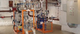
An automated control unit is a set of equipment and devices designed to provide automatic regulation of temperature and coolant flow, which is carried out at the input of each building in accordance with the temperature schedule required for an individual building. Adjustments can also be made according to the needs of the residents.
Water heater piping unit.
Among the advantages of the ACU, when compared with elevator and thermal units that have a fixed cross-section of the passage opening, is the possibility of varying the amount of coolant, which depends on the temperature of the water in the return and supply pipelines.
In this case, the installation is carried out after the unit that takes into account the thermal energy of the system.
Image 1. Schematic diagram of an ACU with mixing pumps on a jumper for temperatures up to ACU t = 150–70 ˚C with one- and two-pipe heating systems with thermostats (P1 – P2 ≥ 12 m water column).
The automated control unit is represented by a diagram illustrated in PICTURE 1. The diagram provides: an electronic unit (1), which is represented by a control panel; outdoor temperature level sensor (2); temperature sensors in the coolant in the return and supply pipelines (3); valve for regulating flow, equipped with a gear drive (4); valve for adjusting the differential pressure (5); filter (6); circulation pump (7); check valve (8).
As the diagram shows, the control unit fundamentally consists of 3 parts: network, circulation and electronic.
The network part of the ACU includes a coolant flow regulator valve with a gear drive, a differential pressure regulator valve with a spring control element and a filter.
The circulation part of the control unit includes a mixing pump with a check valve. A pair of pumps are used for mixing. In this case, pumps must be used that satisfy the requirements of the automatic unit: they must operate alternately with a cycle of 6 hours. Their operation should be monitored by a signal from a sensor that is responsible for the pressure difference (the sensor is installed on the pumps).
Heating system regulator that saves heat up to 30%.
Optimizing the temperature regime using a heat and power regulator allows you to save heat energy up to 30% and, accordingly, reduce your utility bill. The greatest savings occur if the house switches from payment mode according to the standard to payment according to metering devices using a heat and power regulator.
Description:
In many residential buildings there is a problem of improper heating distribution. Because of this, some people live in poorly heated rooms, while others are forced to suffer due to the heat. The heating system regulator “adjusts” to the temperature parameters of the house and allows you to save up to 30% of the cost of thermal energy. This provides comfortable conditions for residents of houses and allows them to save on housing and communal services.
This heating system regulator independently and automatically measures temperatures and other thermal parameters in the supply and return pipelines, as well as the temperature outside the house, in order to identify a lack or excess of heating and automatically adjust them. It “reads” the temperature values inside the pipe using digital sensors - in the range from -55 to +125 °C - and sends commands to the actuator. The heat and power regulator also registers and stores this data.
If the supply of thermal energy or the pressure of hot water is reduced or increased for some reason, the heating system regulator can automatically adjust the pressure to normal by controlling pumps and other actuators in the building. The device software allows you to monitor heating modes by time of day, days of the week, depending on the outside temperature, and also solve other problems.
Regulator size – 105x105x60 mm.
Optimizing the temperature regime allows you to save heat energy up to 30% and, accordingly, reduce your utility bill. The greatest savings occur if the house switches from payment mode according to the standard to payment according to metering devices using a heat and power regulator.
Advantages:
– heat energy savings up to 30%,
– controls pumps and other actuators,
– the cost of installing a common house heating system regulator, taking into account the price of sensors, actuators and work, is about 100,000 rubles, which pays off already in the first months of use,
– no installation restrictions.
mazda 626 gd heating system regulator system automatic heating system regulators temperatures in heating systems automatic heating system return regulator settings parameters for heating system regulators book heating system project school temperature regulator water pressure regulator in the heating system of an apartment building after itself operating principle differential pressure regulator heating system flow make-up temperature controller for coolant flow in the heating system of an apartment building electric electronic water temperature controller in a gas heating system mechanical common house price
Why is it more profitable to install ACU in buildings with high heat consumption?
The heating control unit costs approximately the same for large and small buildings (the difference in the cost of equipment and installation is 20%-30%).
At the same time, in a large building you can save 5-10 times more thermal energy than in a small building.
In our example we see:
- The heating control unit pays for itself in 10.5 years in building No. 1, with an area of 1,300 m2 and a heat consumption of 340 Gcal before installing the ACU.
- The same unit pays for itself in 1.5 years in building No. 3, with an area of 18,500 m2 and a heat consumption before installing an ACU of 4,400 Gcal.
Our analysis and calculation are not universal.
They only give you a basic understanding of which buildings make the most sense to install automated heating control units.
We recommend calculating the feasibility and payback period of the heating control unit individually for each building, based on specific circumstances and conditions.
