Automatic heat control system (SART)
TeleSystems LLC proposes the implementation of an automatic control system for heat consumption (SART) in order to ensure the rational use of thermal energy and create comfortable conditions for living and working.
Each of us has noticed more than once that during periods of warming, the radiators in the building remain as hot for a long time as in cold weather. Unfortunately, the centralized heating system in our country is characterized by inertia: correction of the coolant temperature at the heat source is carried out with a noticeable lag. Moreover, the centralized system is always focused on the average consumer, as a result of which in buildings located closer to the heat source, overestimated coolant parameters are always observed. In an effort to provide ourselves with comfortable living and working conditions, we open the windows, and the heat we pay for goes outside. And therefore, here lies the source of energy savings.
You can save on heat consumption by installing an automatic coolant temperature control system (CART) in the individual heating station of the building. It is designed to regulate heat consumption by increasing or decreasing the flow of coolant into the building, depending on its real needs at the moment.
How to regulate?
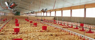
Today, there are special devices that are designed to automatically regulate the temperature inside the greenhouse.
But this equipment sometimes turns out to be too expensive to export, especially if there is more than one greenhouse.
In such cases, you can use cheaper and fairly simple methods that can effectively reduce or increase the temperature. In addition, it is worth noting that some of them are more effective compared to modern technical devices.
In order to quickly raise the air temperature in a building, you must use one of the following methods:
- Covering the greenhouse with an additional layer of plastic film in order to create an air gap that does not react to various environmental factors.
- Inside, a so-called secondary greenhouse is made - an additional cover is attached to a previously prepared structure, so that it is located directly above the surface of the plants.
- Thorough mulching of the soil layer makes it possible to attract heat to the plants using polyethylene film or black spunbond.
There are also methods that allow, if necessary, to lower the temperature level inside greenhouses. The most common ones include:
- Greenhouses should not be made too long.
- There should be free access of air flows from the environment through the gables.
- The structure is treated with a special chalk solution.
- Watering the growing vegetable crops with a sufficient amount of water in the morning.
If automatic devices are used, then you can use such effective methods as correct control of the system intended for heating the greenhouse, as well as opening the vents after the thermostat has given the appropriate command.
The main tasks of SART:
- Elimination of the supply of coolant to the facility with overestimated (“overheating”) and underestimated parameters, while the regulation of the coolant parameters depending on the outside air temperature occurs with minimal inertia - SART performs the correction instantly.
- Regulating the temperature of the coolant in the return pipeline of the heating network to eliminate the application of penalties by energy supply organizations for exceeding this temperature. SART allows you to limit the coolant intake from the network and re-enter it from the return pipeline into the heating system. And so on until his temperature reaches normal.
- Saving thermal energy by lowering the coolant temperature at night, as well as on weekends and holidays. For example, if a workshop operates in three shifts without days off, then this mode is not applicable, but if there is no staff in the workshop at night and on weekends (holidays), then it is possible to reduce the temperature of the coolant during this time.
- Maintaining a given temperature regime in the building using sensors located in control rooms. This will not save money, but will provide comfortable living and working conditions. The difficulty lies in selecting a control room for installing the sensor, taking into account that the temperature in it will affect the climate in the entire building. It is used, as a rule, for objects with a clearly defined control room, where it is necessary to ensure the greatest comfort with a variable schedule: cinemas, swimming pools, etc.
Also, the system developed by our specialists provides the technical ability to issue signals to a unified dispatch center when the regulated parameters go beyond the control limits. This significantly increases its reliability and minimizes the likelihood of system and equipment failure.
Benefits from implementing SART
The cost of creating a SART (design, installation and delivery to the ESO) by specialists of TeleSystems LLC, according to the price list, starts from 250 thousand rubles.
Our calculated average values of possible savings in thermal energy consumption using all algorithms of the SART module:
- application of weather control
16%, application of scheduled regulation
Total: total savings are about 38%.
In addition to savings and comfortable living conditions, the implementation of SART ensures balancing of the heating system, increases the service life of heating system equipment, increases the attractiveness of the house and ensures compliance with legislative requirements for energy saving.
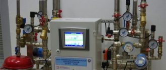
Composition of the regulatory system
SART is a system of temperature sensors, a control valve, pumps, a controller and communication equipment (if remote control of the system is required). Using installed sensors, the temperature outside and inside the house, as well as the temperature in the supply and return pipelines, is analyzed. This data is transmitted to the control cabinet controller. The controller analyzes the sensor readings and issues a command to the control valve in accordance with a given schedule.
The control unit allows:
- set the temperature control mode for each day of the week, taking into account working and non-working hours;
- automatically maintain the specified mode for regulating the coolant supply;
- adjust the temperature regime and calendar when shifting working days and weekends;
- programmatically set the configuration of the heat control system from a set of standard schemes.
- facility supply line schedules;
- object return line schedules;
- hourly graphs of the regulator operating mode;
- normalized room temperature;
- standardized temperature at the boiler outlet;
- characteristics of valves and hydraulics; pump operating modes.
An automatic heat control system is installed on existing pipelines.
The cost of SART and its payback period are determined after the Customer fills out the questionnaire and processes it by the specialists of TeleSystems LLC. According to the experience of our company, residents’ investments pay off in 1 to 1.5 heating periods, while the service life of the equipment, if used correctly, is at least 15 years.
Our specialists have many years of experience in installing SART. We use reliable equipment from well-known manufacturers such as Danfoss, Wilo, Grundfoss, etc. Contact us and we will help you choose the best option for you. Preliminary examination is free.
Additionally, we recommend installing a module for commercial metering of consumed thermal energy in the heating station. Its installation will allow you to pay for real heat consumption, rather than calculated, and thus reduce heating costs.
Based on the experience of installing heat metering modules, the average savings during the heating season are:
- in residential brick buildings (taking into account the termination of payment for excess losses) - up to 40%;
- at social facilities (schools, kindergartens, hospitals, sanatoriums, etc.) - up to 40%;
- in residential panel buildings – up to 35%;
- in office buildings and administrative buildings – up to 25%;
- in industrial buildings (production workshops, warm warehouses, etc.) - up to 20%.
An integrated approach to energy saving
– Conducting energy surveys: from express surveys to in-depth energy surveys, from audits of products and technological processes to audits of a group of enterprises.
– Formation of energy saving programs both for an individual enterprise and for a region based on the results of energy surveys.
– Implementation of energy saving programs: from installing energy meters to renovating buildings.
A special place in the company’s product line is occupied by a number of complex products aimed at automating the accounting and management of energy resources based on the “Bee.Net” software developed by the company’s specialists.
© TeleSystems LLC Address: 620028, Ekaterinburg, st. Melnikova, 20 Tel./fax
Magnetoelectric temperature indicators
Rice. 2. Magnetoelectric temperature indicator: a — TM100 sensor with a thermistor; b - measuring element of the receiver; c — view of the receiver with the scale removed; d - electrical circuit of a magnetoelectric temperature indicator.
Later, instead of these devices, magnetoelectric indicators began to be installed. The sensor (Fig. 2, a) of this indicator is a cylinder 1, to the bottom of which a thermistor 3 is pressed to the bottom by a current-carrying spring 2. The resistance of the thermistor changes within a wide range when its temperature changes (50-450 Ohms).
The receiver (Fig. 2, b and c) has a frame 4, consisting of two plastic halves connected by coupling screws 10. The windings of three measuring coils 8 are wound on the plates. The second winding is located at an angle of 90° to the other two. To increase the sensitivity of the device, the first and third coils have opposite directions of winding turns, as a result of which the resulting magnetic fluxes are directed towards each other. Inside the frame there is a permanent magnet 9 mounted on the same axis 7 with the arrow. The magnet can rotate, orienting itself along the magnetic field lines of the three coils.
In the lower half of the frame there is a thrust bearing 11 for the axis of the disk-shaped magnet and the arrows. One end of the magnet axis is placed in the hole of the bridge 6, which is fixed to the frame and serves as a support for the instrument scale.
To return the moving system to the zero position when the device is turned off, a small magnet is built into the lower half of the frame. The frame assembly with coils and magnet is placed in a shielding cylinder 5 made of low-carbon steel to eliminate the influence of extraneous magnetic fields on the magnet and eliminate the influence of the magnetic field of the coil on the readings of other instruments.
The measuring unit 12 of the receiver is mounted in the instrument cluster or in the housing of a separate device. In both cases, the ends of the windings are connected to the output terminals and resistors 14 and 16. The receiver has a regulator 13 with a magnet. On the dashboard of the car, the temperature indicator is illuminated by a lamp located in socket 15.
When the sensor and receiver are connected to the power circuit, the current flows through two parallel circuits: windings L1 and L2 of the receiver - temperature compensation resistor R: winding L3 of the receiver - thermistor RT of the sensor (Fig. 2, d). The magnetic fluxes of windings L1 and L3 are directed in opposite directions.
In the receiver housing (for a voltage of 12 V), together with the mechanism, there is a temperature-compensation constantan resistor R, which ensures stability of readings when the temperature of the receiver windings changes. In addition, in the housing of the receiver, designed for 24 V, there is an additional resistor 16 (see Fig. 2, c), connected in series with the windings of the receiver. This connection circuit makes it possible to unify the design and winding data of temperature indicators for their use in electrical equipment systems of cars for on-board voltage of 12 and 24 Volts.
Choosing a heat control system with maximum efficiency
In accordance with the requirements of regulatory documentation and Federal Law No. 261 “On Energy Saving...”, the installation of automatic weather control systems should become the norm, both for new construction projects and for existing buildings, since this is the main tool for heat supply management. Today, such systems, contrary to popular belief, are quite accessible to most consumers. They are functional, highly reliable and allow you to optimize the process of thermal energy consumption. The payback period for the installation of equipment is within one year.
The automatic heat control system (SART) allows you to reduce thermal energy consumption due to the following factors:
- Elimination of excess thermal energy (overheating) entering the building;
- Decrease in air temperature at night;
- Decrease in air temperature on holidays.
Integrated indicators of thermal energy savings from the use of SART installed in an individual heating point (IHP) of a building are presented in Fig. No. 1.
Fig.1 Total savings reach 27% or more*
*according to NPP Elekom LLC
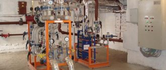
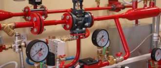
The main elements of classical SART are shown in general form in Fig. No. 2.
Fig.2 Basic elements of SART in ITP*
*auxiliary elements are not shown
Purpose of the weather controller:
- Measurement of outside air and coolant temperatures;
- Control of the KZR valve depending on the established regulation programs (schedules);
- Data exchange with the server.
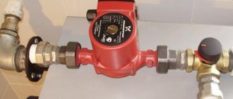
Purpose of the mixing pump:
- Ensuring constant coolant flow in the heating system;
- Ensuring variable coolant mixing.
Purpose of the KZR valve:
control of the supply of coolant from the heating network.
Purpose of temperature sensors: measuring coolant and outside air temperatures.
- Differential pressure regulator. The regulator is designed to maintain a constant pressure drop of the coolant and eliminates the negative impact of an unstable pressure drop of the heating network on the operation of the SART. The absence of a differential pressure regulator can lead to unstable operation of the system, reducing the economic effect and service life of the equipment.
- Room temperature sensor. The sensor is designed to monitor indoor air temperature.
- Data collection and control server. The server is designed for remote monitoring of equipment performance and correction of heating schedules based on readings from indoor air temperature sensors.
The principle of operation of the classical SART scheme is qualitative regulation, complemented by quantitative regulation. Qualitative regulation is a change in the temperature of the coolant entering the heating system of the building, and quantitative regulation is a change in the amount of coolant coming from the heating network. This process occurs in such a way that the amount of coolant supplied from the heating network changes, but the amount of coolant circulating in the heating system remains constant. Thus, the hydraulic mode of the building’s heating system is maintained and the temperature of the coolant entering the heating devices changes. Keeping the hydraulic mode constant is a necessary condition for uniform heating of the building and efficient operation of the heating system.
Physically, the control process occurs like this: the weather controller, in accordance with the individual control programs embedded in it and depending on the current temperatures of the outside air and coolant, supplies control actions to the KZR valve. When in motion, the shut-off element of the KZR valve reduces or increases the flow of network water from the heating network through the supply pipeline to the mixing unit. At the same time, due to the pump in the mixing unit, a proportional selection of coolant is carried out from the return pipeline and mixed into the supply pipeline, which, while maintaining the hydraulics of the heating system (the amount of coolant in the heating system), leads to the required changes in the temperature of the coolant entering the heating radiators. The process of reducing the temperature of the incoming coolant reduces the amount of thermal energy that is taken per unit time from the heating radiators, which leads to savings.
SART diagrams in ITP of buildings from different manufacturers may differ slightly, but in all schemes the main elements are: weather controller, pump, KZR valve, temperature sensors.
I would like to note that in conditions of the economic crisis, an increasing number of potential customers are becoming price sensitive. Consumers are beginning to look for alternative options with the least amount of equipment and cost. Sometimes along the way there is a mistaken desire to save money by installing a mixing pump. This approach is not justified for SART installed in ITP buildings.
What happens if you don't install a pump? And the following will happen: as a result of the operation of the KZR valve, the hydraulic pressure drop and, accordingly, the amount of coolant in the heating system will constantly change, which will inevitably lead to uneven heating of the building, inefficient operation of heating devices and the risk of stopping the coolant circulation. In addition, at negative outside temperatures, the heating system may “defrost”.
It’s also not worth saving on the quality of the weather controller, because... Modern controllers allow you to select a valve control schedule that, while maintaining comfortable conditions inside the facility, allows you to obtain significant amounts of thermal energy savings. This includes such effective heat management programs as: eliminating overheating; reducing consumption at night and on non-working days; elimination of overestimation of return water temperature; protection against “defrosting” of the heating system; correction of heating schedules based on indoor air temperature.
To summarize the above, I would like to note the importance of a professional approach to the selection of equipment for a weather automatic control system for heat consumption in a building’s ITP and once again emphasize that the minimum sufficient basic elements of such a system are: a pump, a valve, a weather controller and temperature sensors.
23 years of work experience, ISO 9001 quality system, licenses and certificates for the production and repair of measuring instruments, SRO approvals (design, installation, energy audit), accreditation certificate in the field of ensuring uniformity of measurements and recommendations from clients, including government agencies, municipal administrations, large industrial enterprises allow the ELECOM company to implement high-tech solutions for energy saving and increasing energy efficiency with an optimal price/quality ratio.
Installation and connection
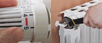
Installation of a room temperature controller is carried out in several stages:
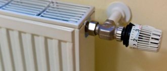
- Mount the regulator on the wall at a height of 150-160 cm away from heating radiators, various heaters, and places exposed to direct sunlight;
- Connecting to the contact group of the cable regulator - the bare and preferably soldered ends of the cable are inserted into special connectors and secured with screws;
- Laying the cable from the thermostat to the heating equipment in plastic cable channels;
- Connecting the cable to the corresponding terminals on the boiler control board, servo drive of the three-way valve on the radiator.
Weather-compensated automation with shut-off valve and circulation pump.
And finally, the last type of automation for maintaining the temperature in apartments of residential buildings, depending on the temperature outside, is weather-dependent automation with a shut-off and control valve and a circulation pump.
Let's look at the principle of operation of this automatic temperature control system in an apartment, or rather, in an entire apartment building.
Here, temperature control in the heating system occurs by changing the valve capacity and, as in the previous scheme, mixing returned (return) network water from a residential building using a circulation pump, now installed on the return pipeline of the heating system. In principle, where the network or circulation pump will be installed is generally unimportant; it’s just that for a two-way valve such a scheme is still preferable due to its design features.
During the regulation process, the controller also periodically polls the coolant temperature sensors in the heating system of the house, indoor air sensors (if installed) and an outdoor air sensor. After processing the received information, the controller generates an output control signal to open or close the actuator of the two-way valve, and the value of opening or closing the flow area of the control valve changes accordingly. In the absence of an indoor air sensor, the main priority of regulation is also to maintain the temperature in the apartments according to the temperature schedule.
There is only one drawback of control schemes with valves - loss of electricity. For more information about the advantages and disadvantages of weather-dependent automation, see the article on weather control with a control elevator. The advantage of weather control schemes with valves over a control elevator is usually called the depth of regulation, although in our opinion such an advantage is controversial and can easily turn into a disadvantage if, for example, the ITP has a thermal energy metering unit, and its measurement limits are worse than the operating limits of automatic weather control. After installing automatic weather control without agreement with the energy supply organization, such a heating system can legally be recognized as non-commercial, which means that instead of saving, you will again receive payment for heat according to the standard.
- insufficient pressure at the inlet to the ITP, less than 0.07 mPa
- excessive resistance of the internal heating system of the house, more than 5 m.w.c.
- installation of automatic control valves on heating devices and risers, for example
- use of an independent heating system through heat exchangers.
I would also like to warn residents who are especially concerned about saving money that weather-compensated automation circuits with mixing valves cannot be used without a pump or with the pump turned off . In the operating mode with the pump turned off, the pumping of coolant through the heating devices sharply decreases; the difference in temperatures between the temperatures in the heating devices of different apartments sometimes reaches 45 degrees, instead of the twelve recommended for the economical mode of operation of weather-compensated automation. And most importantly, due to the lack of mixing in cold weather, the temperature in the heating devices of the first apartments along the route can reach 115 degrees or more, which will inevitably lead to the failure of modern polypropylene pipes , as well as burns from accidental touching of the heating devices - this is at a minimum. At the same time, the residents of the last apartments along the coolant path will sit in the cold.
This is the savings, and everything will be OK according to the instruments. And most importantly, if the check valve on the jumper between the direct and return pipelines fails, not only your home, but the entire area may be left without heat. The coolant will not go to the apartments, but will return back to the boiler room.
We examined possible options for schematic solutions for implementing weather-dependent automation in the control framework of multi-storey residential buildings. In any case, the decision to choose one or another weather-dependent temperature control scheme in the apartments of a residential building, and most importantly the selection of equipment, should be entrusted to specialists. You, as residents, should have your say only when choosing a design organization and the type of equipment - domestic or imported. The price depends on this.
All about the prices for design work, purchased equipment and installation and adjustment of automatic weather control in apartments of residential buildings on the next page.
Types of industrial thermostats
Thermostats for greenhouses of varying degrees of complexity can be purchased at the appropriate stores, or assembled with your own hands (if you have the necessary skills).
Types of thermostats.
Today, three types of models of these devices are produced:
- Touch temperature controllers are quite expensive multifunctional systems. Designed primarily for large greenhouse complexes. It is possible to set many programs that control the operation of the heating system. They can even take into account the heat generated by rotting manure. They have a large number of different functions and are usually equipped with a backlit display.
- Electronic thermostats are devices whose number of functions is noticeably less than that of regulators of the previous class, but the price is correspondingly lower. Usually equipped with a switch that makes it possible to set a specific heating mode. For convenience, they are often supplemented with a liquid crystal display with the necessary information.
- Mechanical thermostats are the simplest in design, but often no less effective devices than their electronic counterparts. Purchasing, for example, expensive equipment for a small country greenhouse is not economically feasible. But an inexpensive mechanical thermostat would be the most suitable option for it.
When purchasing any of these devices, you should pay special attention to the following characteristics:
- the power of the heating installation being serviced and its capabilities;
- the specificity of installations that may be required;
- does this device have all the required functionality?
- ease of operation and suitable appearance.
In order to install a heat saving system in your home, you need:
Application
Survey
Visit of a specialist to the site and commercial offer - free of charge
Agreement
We carry out major and current repairs
Project
We develop an individual project. Approval from supervisory authorities
Installation
In any season. Quality assurance. Right on time.
Commissioning
We carry out commissioning work. Setting the optimal heat consumption mode at home.
in the period from 2013 to 2022, existing heating units were retrofitted with weather-dependent automatic heating and maintaining the set hot water temperature. The heating and hot water systems are equipped with 2-circuit ART-05 regulators, control valves with electric drives and circulation pumps.
Apartment buildings, administrative and industrial buildings, as well as institutions of the Department of Culture of the Vladimir Region were retrofitted with weather-dependent automation.
The average monthly result of heat savings with proportional heating control was 20%. At the same time, the problem of uniform heating of heating devices throughout the house and the absence of overheating was solved.
By agreement with the customer, it is possible to establish a daily schedule for regulating the temperature of heating and hot water for additional savings and comfort for residents of the apartment building.
How to choose thermostats with an air temperature sensor
When choosing a thermostat, you are guided by several factors:
- method of heating premises;
- type of thermal installation;
- type of heaters;
- number of rooms and heating area;
- the time when people will be absent from the house;
- financial opportunities.
Considering these conditions, the consumer can choose a mechanical or electrical TP. If you need to regulate heating in 2-3 rooms, you can install an electronic regulator and place sensors in each room. For mansions with 2-3 floors, a climate system with a universal programmable thermostat is suitable.