Temperature control is ubiquitous in technological processes, allowing you to select the appropriate operating mode or monitor changes in the state of the material. Temperature conditions are equally important when turning on the oven in the kitchen, as well as in blast furnaces when melting steel, and deviation from normal operation can lead to an accident and injury to people. To avoid unpleasant consequences and ensure the ability to regulate the degree of heating, a temperature sensor is used.
Sensor DS18B20: characteristics
- temperature measurement range -55 … +125 °C;
- sensor error does not exceed 0.5 °C;
- resolution reaches 0.0625 °C;
- The DS18B20 sensor is factory calibrated;
- you can connect up to 127 sensors on one line;
- Only 3 wires are required for connection.
Connecting and pinout of the ds18b20 temperature sensor
The DS18B20 digital sensor sends data via the Wire bus and can work on the same line with many other devices. Each sensor has its own personal 64-bit code, which allows the Arduino microcontroller to communicate on one bus with several sensors at once. The sensor converts the ambient temperature into a digital code, i.e. no additional ADC is required for connection.
The sensor can be made in several versions (see photo above), only the connection diagram of the temperature sensor to the Arduino NANO or UNO will depend on this. In the first case, it is necessary to use a 4.7 kOhm pull-up resistor. The sensor, in the form of a finished module, already has a resistor. The third option is a sensor in a sealed housing that can be safely used in hot water.
Sources of uncertainty in on-site temperature measurements
The new standard GOST R 8.625-2006 provides rules for rejecting a resistance thermometer by the consumer. They established that a thermometer can only be rejected if the deviation of the thermometer’s resistance from the NSX lies completely outside the range due to the expanded uncertainty of temperature measurement under operating conditions. Therefore, the problem of assessing the uncertainty that arises when measuring temperature at an object becomes very relevant. Sources of uncertainty in temperature measurement with an industrial resistance thermometer can be divided into sources associated with the physical operating conditions of the vehicle and electrical signal conversion:
thermal conductivity properties of a given thermometer design and mounting elements, heat transfer by radiation to the environment, thermal capacity of the temperature sensor, rate of change of the measured temperature, current leakage (grounding quality), electrical noise, accuracy of the meter or signal converter.
Checking temperature sensors
Temperature control module connection diagram.
After such a device is connected, you need to check how it works. To do this, you will need a regular tester for measurement, and for sensors with a resistance of 0 degrees to 100 Ohms, the optimal measuring range of the tester is up to 200 Ohms.
The test is carried out at room temperature, and it is possible to determine which wires are short-circuited near the device; in most cases, the resistance between the wires is much less than that of the sensor. Then you need to check that the device is working, that is, whether it produces the resistance that it should produce at a certain temperature.
In the end, you need to make sure that the device does not short-circuit to the body of the thermal converter; this can be checked in the megaohm range of resistance between the sensor body and the wires
It is very important to follow safety precautions, that is, you should not touch the housing contacts, and you should not touch the wires either.
If the tester indicates infinite resistance, it means that water or grease has entered the sensor housing. Such a device may function for some time, but the accuracy of the readings will constantly decrease, its readings will float.
How to choose?
When choosing a temperature sensor, you must be guided by the following criteria:
- if the sensor is in contact with or located inside the measured medium, then a contact model is taken, if it is located outside the object, then a non-contact model;
- the conditions and state of the environment in which it will operate (humidity, aggressive substances, etc.) must correspond to the capabilities of the sensor;
- the step and calibration of measurements should ensure convenient operation of both the sensor and the equipment;
- if the sensor must be replaced during operation, then replacement options are installed;
- when choosing a temperature sensor to replace a faulty one, it is better to use its VIN code;
- The operating temperature limit must cover all possible heating values, some of which are shown in the table below.
Table: temperature limits of thermoelectric type sensors
| Type | Compound | Temperature range |
| T | copper/constantan | -250 °C to 400 °C |
| J | iron/constantan | -180°C to 750°C |
| E | chromel/constantan | -40 °C to 900 °C |
| K | chromel / alumel | -180 °C to 1,200 °C |
| S | platinum-rhodium (10%) / platinum | from 0 °C to 1,700 °C |
| R | platinum-rhodium (13%) / platinum | from 0 °C to 1,700 °C |
| B | platinum-rhodium (30%) / platinum-rhodium (6%) | from 0 °C to 1,800 °C |
| N | nichrosil / nisil | -270 °C to 1,280 °C |
| G | tungsten / rhenium (26%) | from 0 °C to 2,600 °C |
| C | tungsten-rhenium (5%) / tungsten-rhenium (26%) | from 20 °C to 2,300 °C |
| D | tungsten-rhenium (3%) / tungsten-rhenium (25%) | from 0 °C to 2,600 °C |
Characteristics of the lm35 sensor, description
— power: 2.7-5.5 Volts; — current consumption: 50 mkA; - temperature range: 10°C - 125°C - error: 2 degrees.
Instead of lm35, you can use any other temperature sensor, for example, TMP35, LM35, TMP37, LM335. The sensor looks like a transistor and is therefore easy to confuse, so always carefully read the markings on the radio elements. Manufacturers often make temperature modules for Arduino based on this sensor (see photo above). If you only have the lm35 sensor itself, then it has three outputs.
LM35 connection circuit, how it works (datasheet)
If you look at the lm35 temperature sensor from the side of the contacts and cut upward (as in the figure), then on the left there will be a positive contact for power supply of 2.7-5.5 Volts, the contact in the center is the output, and on the right is the negative power contact (GND) .
Connecting LMT01 to ATiny25
Rice. 13. Layout and connection diagram of LMT01 to the ATiny25 microcontroller
Rice. 14. Connecting LMT01 to the ATiny2 microcontroller | Rice. 15. Oscillograms of signals at pin 7 of the ATiny25 |
| Figure 13 shows the diagram and layout of connecting LMT01 to the microcontroller ATiny25 in SOIC-8 package. In this case, an additional switch on a bipolar transistor was used. Using a transistor allows you to send a signal to any digital input port of the microcontroller without a comparator. Figure 14 shows the circuit in action. Don't be fooled by the large development board MSP432 – it only uses a UART/USB converter. The temperature value without the fractional part is displayed in the terminal, which simplifies and shortens the program code. Oscillograms of signals from LMT01 can be viewed in Figure 15. The program for ATiny25 is written in C (GCC) and uses pulse counting based on interrupts from the INT0 input. Clock frequency – 8 MHz. Timer TIMER1 is used to count time intervals. The original project “LMT01 demo programm for ATtiny25 MCU” and additional information can be found in the code example archive for LMT01 . |
Classification of types of temperature sensors
The choice of sensor depends on the environment in which the temperature needs to be monitored: inside the boiler, in the room or in the heating system. The efficiency and safety of heating equipment depends on the correct choice.
The temperature sensor for a heating boiler is classified according to the following criteria:
- by the method of determining temperature;
- by type of interaction with the thermostat.
Types of sensors by method of determining temperature
According to the method of determining temperature, sensors are:
- Dilatometric, which are bimetallic plates or spirals, the operating principle of which is based on the thermal expansion of metals or other types of solids.
- Resistive, having a strong dependence on temperature in a certain measured range, which manifests itself in the form of sharp changes in electrical resistance.
- Thermoelectric, which are thermocouples (alloys of two dissimilar conductors, for example, chromel-alumel), in which thermo-EMF begins to induce at certain temperature intervals.
- Manometric, the principle of operation of which is based on changing the pressure of a gas or liquid in a closed volume.
Dilatometric sensors are made from materials with a high coefficient of thermal expansion that respond to minimal temperature fluctuations. The principle of their operation is based on the closing or opening of electrical contacts. To increase their sensitivity and quality of contact, magnets are used in structures.
Resistive temperature sensors are made from special alloys of conductors or semiconductors. Structurally, they consist of a coil with a wound thin copper, platinum or nickel wire and a ceramic housing or semiconductor wafers placed in a plastic or glass housing.
Semiconductor resistors come in two types:
- thermistors having a nonlinear temperature dependence, characterized by a decrease in resistance when heated;
- posistors, which also have a nonlinear dependence on temperature, but differ from thermistors by increasing resistance when heated.
Thermoelectric sensors are made of two specially selected dissimilar metals or alloys, at the point of contact of which, when heated, a thermo-emf is induced, the value of which is proportional to the temperature difference between the two junctions. In this case, the measured value does not depend on temperature, length and cross-section of wires.
Gauge sensors allow you to determine temperature in a non-magnetic way without the use of energy sources, which allows them to be used for remote measurements. However, their sensitivity is an order of magnitude worse than that of other temperature sensors, and there is also an inertia effect.
Types of sensors according to the method of interaction with the thermostat
Temperature meters based on the type of interaction with the thermostat are divided into the following types:
- wired, transmitting data to the controller via wire;
- wireless – high-tech modern devices that transmit data at a certain radio frequency.
Wired temperature sensor for boiler
Application
The scope of application of temperature sensors covers both household appliances and equipment for general industrial use, the agricultural industry, the military industry, and the aerospace sector. Each of you can find them at home in heating appliances - boilers, ovens, multicookers or bread makers.
In heavy industry, thermal sensors make it possible to control the degree of heating of furnaces, air in the working area, and the condition of rubbing surfaces. In medicine, they are used to control temperature in hard-to-reach places or to simplify various procedures.
Many car enthusiasts often come across temperature analyzers that monitor the condition of oil or other coolant. On the railway network, they make it possible to monitor the heating of axle boxes and wheel sets. In the energy sector, they are used to examine contact connections and the quality of surface contact.
Features of working with the sensor:
Like the similar analog sensor LM35, the output generates a voltage proportional to the temperature on the Celsius scale, the voltage value is also 10.0 mV per 1°C, but unlike the LM35, where the countdown starts from 0°C and at 25°C the sensor generates a voltage of 250mV , TMP36 counts from -50°C, and at 25°C the sensor output will be 750mV.
TMP36 does not have the main disadvantage of LM35 when used together with Arduino, the inability to measure negative temperatures, but the disadvantages still stick out. When using the microcontroller's built-in 1.1 volt reference voltage, the maximum temperature of the sensor is limited to 60°C but this is still suitable for home or outdoor thermometers.
It is highly not recommended to use the supply voltage or the voltage from the built-in 3.3-volt stabilizer connected to the AREF input as a reference voltage for the ADC; the stability of those voltages is extremely low, which will negatively affect the accuracy of the sensor readings. The correct solution would be to use the built-in reference source, and if the upper limit of 60°C is not sufficient, either an external reference source, for example MAX6125, or use another, more suitable temperature sensor.
Signs of breakdown
Like malfunctions of any device in a car, failure of the coolant temperature sensor can lead to undesirable consequences.
When the car is moving, a breakdown may manifest itself as:
- problematic engine starting in cold weather;
- atypical sounds from the exhaust gases when the engine is running;
- when the maximum temperature is reached, the motor stalls;
- The cooling fan does not start when the internal combustion engine heats up;
- excess fuel consumption above the established norm.
Modern cars display data on coolant temperature violations on the display. The cause of the malfunction can be either mechanical failure (broken threads, cracking of the case, burnt out thermistor) or electrical failure (short circuit in the measuring circuit or broken wire). To make sure your assumption is correct, check the sensor and, if necessary, replace it with a new one.
Connecting a motion sensor
No serious security system can do without this sensor. The infrared sensor is the basic element of detecting the presence of warm-blooded animals.
Also, using PIR sensors, it is extremely convenient to control lighting depending on the presence of a person nearby. Infrared or pyroelectric sensors are simple in internal design and inexpensive. They are extremely reliable and rarely fail.
The sensor is based on a pyroelectric or dielectric, capable of creating a field when the temperature changes. They are installed in pairs, and are closed on top with a dome with segments in the form of ordinary lenses or a Fresnel lens. This allows the beams to be focused from different penetration points.
In the absence of heat-emitting bodies in the room, each element has the same incoming radiation dose and, accordingly, the same voltage at the outputs. When a living warm-blooded animal enters the “viewing” zone of the sensors, the balance is disturbed and impulses appear, which are recorded.
HC-SR501 is the most common and popular sensor. It has two variable resistor trimmers:
- one - to adjust the sensitivity and size of the detected object,
- the second is to adjust the response time (the time it takes to generate a pulse after detection).
The connection diagram is standard and will not cause any difficulties.
Correct operation
When operating temperature sensors, the instructions of the boiler and measuring device manufacturer must be strictly followed. In order to ensure the accuracy of measurements, the sensitive element must have the greatest contact with the medium being measured; in addition, it will be necessary to promptly maintain the measuring device and calibrate it within the time limits indicated in the instructions.
Specifics of diesel engine operation in compliance with safety regulations:
- The diesel engine is installed in the environment that must be controlled and regulated by heat exchange;
- during installation, all negative factors that could change the sensor reading must be excluded;
- It is prohibited to operate the meter with damaged insulation;
- It is forbidden to disassemble the sensor yourself;
- All repair and maintenance operations are performed with the meter's networks completely disconnected from the 220V voltage.
Design and principle of operation
The operating principle of temperature sensors is based on measuring resistance, pressure, physical dimensions (thermal expansion), thermal emf, which have a strong dependence on temperature in a specific range. Data on the amount of heating can be obtained based on the calibrations of the sensors when recalculating using the appropriate formulas.
In automatic thermostats, these formulas are embedded in the control program, and in mechanical thermostats, special devices are installed that regulate operating modes in some simple way, for example, mechanical or electrical relays that close or open the necessary contacts.
Thermal sensors have a relatively simple design - a small housing with fasteners, inside which the sensor itself is located. They can be sealed or open, depending on the detection method. To transmit measured data, they can be equipped with wireless sensors or connected via a wired connection.
Main types
Based on the type of the main component of the TPI - the sensitive element or controller, there are four main types:
- Contact TPI. When the temperature changes, the installed contact or electrical circuit opens, a special cable breaks and causes an audible signal. The simplest, usually domestic models, are a closed contact of two conductors, packaged in a plastic container. More complex ones have a temperature-sensitive semiconductor with negative resistance. If the ambient temperature increases, the resistance will drop and a controlled current will flow through the circuit. As soon as it reaches a certain point, the alarm will go off.
- The electronic sensor contains sensors that are located inside the cable; as soon as the temperature reaches a certain threshold, the resistance of the electric current in the cable changes, which is transmitted to the control of the control device. Highly sensitive. The principle of the device is quite complex.
- The optical detector operates on the basis of a fiber optic cable. As the temperature increases, the optical conductivity changes, which leads to an audible warning.
- A metal tube with gas, hermetically filled, is necessary for mechanical TPI. The effect of temperature on any part of the tube will lead to a change in its internal pressure and trigger a signal. Deprecated.
- Other types. Semiconductor ones have a special coating with a negative temperature coefficient, electromechanical ones consist of wires under mechanical tension, coated with a heat-sensitive substance.
OneWire library for working with DS18B20
The DS18B20 uses the 1-Wire protocol to exchange information with Arduino, for which an excellent library has already been written. You can and should use it so as not to implement all the functions manually. You can download OneWire here. To install the library, download the archive and unpack it into the library folder of your Arduino directory. The library is included using the #include command
Basic OneWire library commands:
- search(addressArray) – searches for a temperature sensor; if found, its code is written to the addressArray array; otherwise, false.
- reset_search() – a search is performed on the first device.
- reset() - Perform a bus reset before communicating with the device.
- select(addressArray) – the device is selected after the reset operation, its ROM code is written.
- write(byte) – a byte of information is written to the device.
- write(byte, 1) – similar to write(byte), but in parasitic power mode.
- read() – reading a byte of information from the device.
- crc8(dataArray, length) – calculation of the CRC code. dataArray – selected array, length – code length.
It is important to set the power mode correctly in the sketch. For parasitic power, in line 65 you need to write ds.write(0x44, 1);
For external power, line 65 should be written ds.write(0x44).
Write allows you to send a command to the temperature sensor. Basic commands given in the form of bits:
- 0x44 – measure the temperature, write the resulting value to SRAM.
- 0x4E – Write 3 bytes to the third, fourth and fifth bytes of SRAM.
- 0xBE – sequential reading of 9 bytes of SRAM.
- 0x48 – copying the third and fourth bytes of SRAM to EEPROM.
- 0xB8 – copying information from EEPROM to the third and fourth bytes of SRAM.
- 0xB4 – returns the power type (0 – parasitic, 1 – external).
Advantages and disadvantages
Like any other device, a floor heating thermostat has a number of advantages and disadvantages.
Among the main advantages of the device are:
- Ease of control.
- Affordable pricing policy.
- Saving energy costs
- Ergonomic qualities of the device.
- Ease of installation.
- The ability to automatically configure the system for turning the heated floor on and off.
- The ability to regulate the temperature.
- High quality equipment.
- Reliability of the regulator.
- Installed functional memory , which ensures that the settings are saved in cases of power failure.
Each type of floor has its own type of thermostat.
Connecting and setting up an outdoor temperature sensor
The temperature sensor is connected only to a gas boiler that is disconnected from the power supply. To carry out this process, use a 2 * 0.5 mm cable less than 30 m long. It is pulled through a hole in the wall and connected to the terminal block of the device without observing polarity. The wire is insulated using a special coupling.
The outdoor temperature sensor is connected to the electronic board of the gas boiler. For each model, the connection location may be different; it is determined according to the control board diagram, which is available in the instructions for the unit.
The temperature in the room can be adjusted in the range of 9-30ºС.
The outdoor sensor regulates the temperature of the coolant according to a method that includes the following data:
- Ti – water temperature at the boiler outlet;
- Troom – set room temperature value;
- Te – outdoor temperature sensor readings;
- K – insulation coefficient set by parameter P6.
The coolant temperature is calculated using the following formula:
Ti=[( Troom - Te )·(K/10)]+ Troom.
For example, to maintain a room temperature of 23°C with an insulation coefficient of 10 and an outdoor temperature of -10°C, the coolant must be heated to 56°C.
The most difficult thing in this calculation is the selection of the insulation coefficient, which is determined experimentally. Its setup is done like this:
- on a gas boiler, turn the DHW temperature regulator to maximum, and heating to minimum;
- the temperature contour handle is moved 3 times in the direction of increase within 3 seconds;
- The setting parameter code P6 starts flashing on the LCD display;
- the coefficient value is selected by turning the heating circuit regulator;
- to see the value of the selected parameter, press the reset button;
- to change the indicator, press reset for 2 seconds;
- The factory value 20 will appear on the screen; you can select a parameter in the range from 5 to 35;
- fix the selected value by pressing reset for 2 seconds;
- To exit the setting mode, turn the heating regulator 3 times within 3 minutes.
When choosing a thermal insulation coefficient, it should be taken into account that the higher the value, the worse the building is insulated.
In order for outside temperature sensors for gas boilers to work accurately and efficiently, it is important to find a suitable location for its installation and make the settings correctly. Errors will lead to the fact that the unit will not use fuel economically or the temperature in the house will not be maintained at the proper level
Malfunctions
High-temperature operating conditions of the sensors, especially during unstable boiler operating conditions, lead to the fact that the primary meters fail. The boiler will often shut down if the thermocouple fails periodically, or diagnostics of the boiler operation will signal an error, and the instruments may show an “open circuit.”
Steps to troubleshoot a faulty temperature sensor:
- To repair the diesel engine, I check the correctness of the -ve and + ve conclusions
- I make sure that the cable is installed in accordance with the manufacturer's recommendations.
- I check that there are no external heat sources that could distort the DT readings.
- I check the temperature regulator setting.
- I diagnose possible interruption errors.
- I inspect the sensor for damage.
- I check the faulty thermocouple with a multimeter.
The temperature sensor is the main meter in the boiler safety and control system. It not only performs a protective function, but also contributes to up to 30% savings in thermal energy and gas consumption, since it does not allow overheating and boiler cycling.
Modern Russian requirements for the operation of household boilers oblige all boiler manufacturers to install diesel engines in the safety and protection system; it is better if this work is performed directly at the factory.
Introductory information
If previously there were specialized construction sets with limited sets of functions and strictly defined parameters, today’s variety of construction sets is simply amazing: real microprocessor systems, assembled on the knee, have almost unlimited functionality. Rich imagination, a wide element base, large communities of fans and engineers, and manufacturer support are the main distinguishing features of such robotics kits that are in demand on the market.
One of them, and the most popular, naturally, is Arduino. Constructor for instant assembly of electronic automatic devices of any degree of complexity: high, medium and low. This platform is otherwise called “physical computing” for its close interaction with the environment. A printed circuit board with a microprocessor, open source code, standard interfaces and connecting sensors to Arduino are the components of its popularity.
The Arduino system is a board that combines all the necessary components to provide a full development cycle. The heart of this board is the microcontroller. It provides control of all peripherals. Sensors connected to the system allow the system to “communicate” and interact with the environment: analyze, mark, change.
Blitz tips
- It is necessary to have a normal cross-section of the thermostat cable. If there is wiring from the old days, it is much safer to install a separate line that will come from a specially designated machine.
- When using a thermostat to heat several rooms at the same time , you should remember that temperature control will only be possible in the room where the sensor is located. For this reason, problems with temperature changes are possible.
- It is strictly not recommended to use one regulator in rooms with opposite operating conditions (or with a large temperature difference). It will become impossible to achieve the desired heating in all rooms.
- The best option would be to use a separate thermostat for each room with heated floors.
housetronic.ru
Examples of work for Arduino
One sensor
Let's consider a simple example - connecting one sensor.
The sensor is connected to the control board via one signal pin. When connecting to an Arduino in a compact form factor, such as an Arduino Micro or Iskra Nano Pro, use a breadboard and a couple of push terminals.
Between the signal wire and the power supply, install a resistance of 4.7 kOhm.
When communicating the sensor with standard Arduino boards of Rev3 format, Arduino Uno or Iskra Neo, use Troyka Slot Shield in conjunction with the pull-up module.
Program code
Let's output the sensor temperature to the Serial port.
simple.ino // library for working with the 1-Wire protocol #include // library for working with the DS18B20 sensor #include // signal wire of the sensor #define ONE_WIRE_BUS 5 // create an object for working with the OneWire library OneWire oneWire(ONE_WIRE_BUS); // create an object to work with the DallasTemperature library DallasTemperature sensor(&oneWire); void setup(){ // initialize the operation of the Serial port Serial.begin(9600); // start working with the sensor sensor.begin(); // set the sensor resolution from 9 to 12 bits sensor.setResolution(12); } void loop(){ // variable for storing temperature float temperature; // send a request to measure the temperature sensor.requestTemperatures(); // read data from the sensor register temperature = sensor.getTempCByIndex(); // output the temperature to the Serial port Serial.print("Temp C: "); Serial.println(temperature); // wait one second delay(1000); }
Sensor series
Each DS18B20 sensor stores a unique number in its memory; this solution allows you to connect several sensors to one pin.
Let's add a couple more sensors in parallel to the previous connection diagrams.
Program code
Let's scan all devices on the bus and output the temperature of each sensor separately to the Serial port.
multipleSensors.ino // library for working with the 1-Wire protocol #include // library for working with the DS18B20 sensor #include // signal wire of the sensor #define ONE_WIRE_BUS 5 // create an object for working with the OneWire library OneWire oneWire(ONE_WIRE_BUS); // create an object to work with the DallasTemperature library DallasTemperature sensors(&oneWire); // create an array pointer to store sensor addresses DeviceAddress *sensorsUnique; // number of sensors on the bus int countSensors; // function for outputting the sensor address void printAddress(DeviceAddress deviceAddress){ for (uint8_t i = ; i 8; i++){ if (deviceAddressi 16) Serial.print("0"); Serial.print(deviceAddressi, HEX); } } void setup(){ // initialize the operation of the Serial port Serial.begin(9600); // wait for the Serial port to open while(!Serial); // start working with the sensor sensors.begin(); // search for devices on the bus countSensors = sensors.getDeviceCount(); Serial.print("Found sensors: "); Serial.println(countSensors); // allocate memory in a dynamic array for the number of detected sensors sensorsUnique = new DeviceAddresscountSensors; // determine in which power mode the sensors are connected if (sensors.isParasitePowerMode()) { Serial.println("Mode power is Parasite"); } else { Serial.println("Mode power is Normal"); } // make a request to get sensor addresses for (int i = ; i countSensors; i++) { sensors.getAddress(sensorsUniquei, i); } // print the received addresses for (int i = ; i countSensors; i++) { Serial.print("Device "); Serial.print(i); Serial.print(" Address: "); printAddress(sensorsUniquei); Serial.println(); } Serial.println(); // set the resolution of all sensors to 12 bits for (int i = ; i countSensors; i++) { sensors.setResolution(sensorsUniquei, 12); } } void loop(){ // variable for storing temperature float temperature10; // send a request to measure the temperature of all sensors sensors.requestTemperatures(); // read data from the register of each sensor in turn for (int i = ; i countSensors; i++) { temperaturei = sensors.getTempCByIndex(i); } // output the temperature to the Serial port for each sensor for (int i = ; i countSensors; i++) { Serial.print("Device "); Serial.print(i); Serial.print(" Temp C: "); Serial.print(temperaturei); Serial.println(); } Serial.println(); // wait one second delay(1000); }
Connecting LMT01 to MSP430
Rice. 19. Connection diagram of LMT01 to MSP430G2553
Rice. 20. Connecting LMT01 to Launchpad MSP-EXP430G2
Launchpad MSP-EXP430G2 debugging board is shown in Figure 19. For connection, an option with an internal comparator was used, pulses were counted using a timer. All this significantly simplifies both the connection diagram and the program code. The layout of the device is shown in Figure 20 (in the photo, power is supplied to LMT01 from P2.4, but in the attached example line P1.6 is used for this). The program has many comments in Russian and will be understandable even to a novice developer. The temperature value and “raw” data (number of pulses) are output to the UART at a speed of 9600 bps. The result of the program is shown in Figure 21.
Rice. 21. Temperature measurement with LMT01
In the archive you can find the program code for working LMT01 together with MSP430G2553.
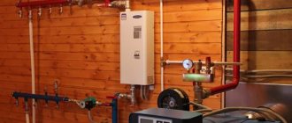
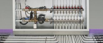
Connecting a temperature sensor for the boiler
All temperature sensors must be connected to a thermostat or a special control controller responsible for the operating modes of the boiler. In this case, it is necessary to carefully study the connection instructions so that the connection requirements match the technical characteristics of the sensors.
It is generally recommended to purchase sensors that are recommended by the boiler manufacturer. This is due to their high compatibility and guarantee of proper operation.
If they are not available for sale, then you need to pay attention to certified analogues.
Connecting an outdoor sensor
The outside temperature sensor for the boiler is mounted on the outside of the wall of the house, subject to the following requirements:
- it is necessary to prevent direct sunlight from hitting its surface;
- the contact surface of the wall must be non-metallic;
- laying cables in places with high humidity, in the presence of chemical or biological factors that can damage the insulation, is prohibited;
- the height of the sensor on the wall should be at 2/3 of the height of the house, if the number of floors is up to three, or between the second and third floors, if the building is multi-story;
- it is necessary to exclude negative factors that reduce the sensitivity or measurement accuracy of the sensor.
External temperature sensor for the boiler
sensor is connected when the power supply to the boiler is turned off. For connection, a solid cable with a core cross-section of 0.5 mm2 and a length of up to 30 m is used. The places where the wires are connected to the boiler and sensor must be sealed and insulated.
When connecting, it is important to observe polarity, depending on the type of temperature sensor. If a section of cable runs along the street, it should be protected with a special corrugated tube
After completing all installation work, you need to check their quality and then adjust the thermostat. If mistakes were made, they should be corrected, otherwise there is a high probability of boiler breakdowns or insufficient heating of the premises.
Connecting a room sensor
The room temperature sensor for the boiler is mounted on the external wall of the building from the inside of the room. The requirements for choosing a location are as follows:
lack of nearby sources of heat or cold; constant access to the space of the room (absence of decorative items, interior items that can obscure the sensor and affect the reliability of measurements); height from the floor should be 1.2-1.5 m; When installing electrical sensors, it is important that there are no sources of electromagnetic radiation nearby: laid electrical wiring, installed powerful electrical appliances, etc. Room temperature sensor for a boiler
Room temperature sensor for boiler
The connection method is similar to the method for an external temperature sensor, and is carried out in accordance with the requirements of the boiler manufacturer. It can be mounted in a specially prepared recess in the wall or on the surface, the main thing is that the sensitive element is not covered from the outside.
Connecting a sensor for a gas boiler
A wireless temperature sensor for a gas boiler is mounted directly on the controller or on the gas valve. Wired temperature sensors are connected in the manner provided by the manufacturer and described in the instructions.
Connecting a water temperature sensor
A water temperature sensor for a boiler in a multi-circuit system is installed on the surface of the heating return pipe or inside it, and installation on a circulation pump is also permissible. This situation is due to the need to prevent high-temperature coolant from getting back into the boiler.
In a single-circuit or single-pipe system, the option of installing the sensor on the return pipe with coolant is prohibited. If the heating increases, the circulation will be blocked and a significant temperature gradient will arise between the far and near rooms.
Varieties
Among the popular brands/models of fire and security sensors on the market, the following products should be highlighted (at the time of writing):
- IP 22051TEI-63-IV is a model of an addressable analogue combined (heat/smoke) detector from the Sphere of Security enterprise. Protection area – 176 sq. m. Dimensions – diameter 102 mm, height 61 mm, weight only 88 g.
- IP 212/101-Bark is a combined detector with heat and smoke sensors combined in one housing. Manufacturer: NPO PAS. Power supply via AL 24 V. Protection – IP Operating temperature range – from – 30 to + 55℃. The maximum number of detectors in the AL is 63 pcs. Dimensions – diameter 100 mm, height 78 mm with a weight of 0.2 kg, which does not exceed the dimensions and weight of a traditional optical smoke detector.
- There are also product models under the abbreviation IP 212/101 from other manufacturers - this is ECO1002, also known as IP 212/101-2-A1R from; IP 212/101-11-PR from ; "Aurora-DTR" (IP 21210/10110-1-A1) from the manufacturer "Argus-Spectrum", operating via a radio channel with a control panel at a range of up to 600 m, as well as a number of other enterprises with similar technical characteristics.
- “S2000-IPG” is a combination of a gas sensor, which determines the content of carbon monoxide in the air, and a maximum differential thermal sensor, combined in a compact housing of an addressable analogue fire detector, the dimensions of which are 100 mm in diameter and 47 mm in height. Power supply: 12 V. Installation type: ceiling. In production.
- IPK-3.3/IPK-3.5 – four- and two-wire combined (smoke/heat) detectors from Ukrainian, operating on a 12/24 V alarm loop.
- MSD-300 is a radio channel combined smoke and heat detector, TSD-1 is a similar device, with 12 V power supply via an alarm loop from Satel from Poland.
- Panasonic 4400 is a multi-sensor smoke detector that, thanks to automatic settings, can be installed in clean, smoky, and hot rooms.
- "Sokol-2" is a combined security detector designed to detect illegal access to enclosed spaces. Its official abbreviation is IO 414-1. It implements double control of the volume of protected space according to two parameters - IR/microwave, i.e. registration of changes in IR radiation after a person crosses control zones formed by an optical sensor, as well as changes in the electromagnetic field created by a microwave sensor. When triggered in any sequence, they generate an alarm by opening the output relay contacts. Range – 12 m. Installation method – wall-mounted. Dimensions – 135x70x50. Can be used at temperatures from – 30 to + 50℃.
- “Sokol-3” is a model of a similar IR/microwave volumetric security detector, designed for installation on the ceiling of a protected room. Dimensions – diameter 90 mm, height 35 mm. The detection range of the sensors is 5 m. Both security detectors are produced domestically.
- The family of security and radio-channel fire detectors with the Astra trademark is a Russian product. Among them are combined IS: “Astra-551” – IR/radio wave security detector with a range of 10 m, detection zone angle 90; "Astra-641" - with an IR/ultrasonic sensor.
The choice is quite large, there are no problems choosing a combined fire and security detector, incl. one manufacturer; because Leading companies that manufacture fire alarm systems, as a rule, produce lines of models of both types, which ensures ease of design using ready-made circuits, full compatibility, reliability of equipment operation, reduced energy consumption, and simplified installation work.
Types of combined fire detectors
How to install the outside temperature sensor correctly?
Thermal sensors are installed on the outer wall of the house
When placing, it is important to fulfill certain requirements:. ...
- It is advisable to install the sensor on a wall that faces north or northeast.
- The sensor should not be exposed to sunlight.
- Do not attach the device to a metal surface.
- The sensor must not come into contact with sources of thermal energy, wind or cold.
- The sensor must be mounted to a flat surface using anchor bolts.
There are also placement rules depending on the number of floors in the house:
- If the building has up to 3 floors, the sensor is installed at 2/3 of its height.
- If the house has more than 3 floors, it is recommended to place the device between the 2nd and 3rd floors.
After the location has been selected, they proceed to installing the street sensor. To gain access to the mounting holes, unscrew the protective plastic cover of the device. Then two wires are connected to the sensor. Use a hammer drill to punch a hole in the wall for fastening, then screw in a dowel for fastening.
What wire can be used to connect room thermostats?
Another important point in connecting the thermostat is the choice of wire. Typically, the cross-section and number of cores are indicated in the instructions for a specific product. In addition, you need to remember the distance from the thermostat to the boiler or hub to which the thermostat is connected - if the output on the thermostat is potential, then the length of the wire can have a significant impact on the operation of the automation. This is due to the voltage drop on the wire. To reduce it, you should take a wire with the largest possible cross-section.
Most often, to connect mechanical thermostats, a two-core wire with a cross-section of 0.5 or 0.75 “squares” is used . For electronic ones, as I described above, it is important to consider the length of the wire. The longer the wire, the larger the cross-section should be (usually the cross-section does not exceed 1.5 “squares”) . But manufacturers do not recommend exceeding the wire length of 100 meters, although this is not specified in the data sheets and instructions for the products.
DHT Sensor Protocol
The sensor output is a digital signal. Temperature and humidity are transmitted via one signal wire (). DHT11 communicates with the receiving end, such as Arduino, using its own protocol. Communication is bidirectional and in general terms looks like this:
- The microcontroller says that it wants to take readings. To do this, he sets the signal line to 0 for a while and then sets it to 1
- The sensor confirms its readiness to transmit data. To do this, he similarly first sets the signal line to 0, then to 1
- After this, the sensor transmits a sequence of 0 and 1, sequentially forming 5 bytes (40 bits). The first two bytes contain temperature, the third or fourth bytes contain humidity, the fifth contains a checksum so that the microcontroller can make sure there are no reading errors.
Thanks to the fact that the sensor only takes measurements when requested, energy efficiency is achieved: while there is no communication, the sensor consumes a current of 100 μA.
Safety precautions
- The device cannot be disassembled; all work must be carried out with rubber gloves; if the equipment is damaged, if the insulation on the power supply cables is missing or damaged, then installation cannot be carried out. You need to remember that electricity is not to be trifled with, and if you do not follow safety precautions, everything can end very badly.
- Such devices may cause interference and may negatively affect the operation of other devices located nearby. This must be taken into account, therefore all devices that operate on electricity must be turned off during work.
- If any difficulties arise, it is necessary that all work is carried out by qualified specialists. Using the instructions above, you can do everything yourself, but if problems arise, it is better not to take risks and entrust them to specialists.
- After completing all the work, you need to make sure that the device is firmly fixed in a certain place. This factor is very important and should not be forgotten.
- When carrying out such work, one must not forget that the equipment is extremely sensitive to water and humidity.
- Any work related to electricity is strictly prohibited during a thunderstorm.
When the device is properly connected, it is necessary to check from time to time how well it functions. Thus, there is nothing complicated in the process, and if everything is done according to the instructions, it will take a small amount of time, and the quality of the work will be excellent.
It should be noted that the quality of such a device must be high, so you should not skimp on it and buy suspicious goods at prices lower than in branded stores. You won’t be able to save money on this, since such a device will soon fail.
1poteply.ru
Connecting a digital humidity, temperature sensor
Two popular sensors - DHT11, DHT22 - are designed to measure humidity and temperature (we will talk about connecting a temperature sensor separately below); Inexpensive solution, great for simple circuits and training. Thermistor, capacitive sensor - the basis of DHT11 and DHT22. The internal chip performs the ADC, giving the output a “digit” that any microcontroller will understand.
DHT11 differs from DHT22 in its measurement range and sampling frequency:
- humidity - 20-80% for DHT11 and 0-100% for DHT22;
- temperature - 0°C to +50°C for DHT11 and -40°C to +125°C for DHT22;
- polling - every second for DHT11 and once every two seconds for DHT22.
Both DHT sensors have standard 4 pins:
- Power supply for sensors.
- Data bus.
- Not involved.
- Earth.
The data and power pins require a 10k ohm resistor between them.
The DHT.h library has been developed for DHT sensors. When loading the sketch into the controller, the port monitor should display the current values of humidity and temperature. It’s easy to check its functionality - just breathe on the sensor and pick it up: the temperature and humidity should change.
It is possible to display values on the LCD 1602 I2C screen if it is included in the system.
Using these sensors, you can build an automated soil watering system outdoors, in a greenhouse, and even on a windowsill. Or organize a system for drying berries - the latter are blown or heated depending on the moisture content of the berries.
Also, some aquaterrariums require special humidity conditions, which can be easily controlled with DHT1 and DHT22.
3Reading data from the DHT11 sensor using Arduino
Let's go this way: download the library for the DHT11 sensor, install it in the standard way (by unpacking it into the libraries directory of the Arduino development environment).
Let's write a simple sketch like this. It will output relative humidity and temperature messages read from the DHT11 sensor to the computer's serial port every 2 seconds.
#include // include the dht11 sensor library;
// initializing the sensor instance #define DHT11PIN 8 // pin 8 will be the DATA bus void setup() {
Serial.begin(9600);
} void loop() {
int chk = sensor.read(DHT11PIN);
Serial.print("h="); Serial.print(sensor.humidity); Serial.print("%t"); Serial.print("t="); Serial.print(sensor.temperature); Serial.println("C"); delay(2000); }
Let's upload this sketch to Arduino. Let's connect to Arduino using the COM port monitor and see the following:
Temperature and humidity data obtained from DHT11 sensor
It can be seen that data on both humidity and temperature are read and output to the terminal.
Connecting the pressure sensor
Often, in predicting the weather or determining the altitude above sea level, it is necessary to solve the problem of measuring pressure. This is where electronic barometers based on MEMS technology come to the rescue: a strain gauge or piezoresistive method associated with the variability of the device resistance when forces deforming the material are applied.
The most popular sensor is BMP085; In addition to barometric pressure, it also records temperature. It was replaced by the BMP180, which has the same characteristics:
- Sensitivity in the range: 300-1100 hPa (if in meters - 9000 - 500 m above sea level);
- Resolution: 0.03 hPa or 0.25 m;
- The operating temperature of the sensor is -40 +85°C, the measurement accuracy in the specified range is ±2°C;
- Connection via i2c standard;
- V1 uses 3.3V for power and logic;
- V2 uses 3.3-5V for power and logic.
Connecting sensors to Arduino in this case is standard. You will need the Unified Sensor Driver - its updated version provides higher accuracy of readings; In addition, it allows you to work with several different connected pressure sensors simultaneously. You must also install the Adafrut_Sensor library.
Diagram of the operation of a mechanical thermostat.
A mechanical room thermostat is the simplest version of a room thermostat, in which a circuit is closed or opened using a bimetallic plate. This thermostat does not require power supply. The scheme by which it works is as follows:
As can be seen from the diagram, there are two ways to connect such a thermostat;
- Via the NC terminal - connection for turning on air conditioners.
- Via the NO terminal - connection for gas and other boilers.
On the other side, you need to connect the wires to the terminal box on the boiler control board. In this case, you must first remove the jumper and secure the ends of the wires with screws.
This connection diagram is the simplest and is used on mechanical and electronic programmable thermostats. In this article I will talk about another scheme.
conclusions
Connecting sensors to Arduino is the transformation of an algorithmic robot, controlled automatically or manually, into a full-fledged environment for the interaction of devices and circuits with the environment. Do not forget - this is not a panacea for all ills. And not the final high-tech product or the final application. Arduino is a set of hardware and software solutions that will help:
- master algorithmization systems for novice engineers;
- master basic design skills;
- learn to program.
Regardless of your level of training, your knowledge, you can always choose tasks within your capabilities. You can put together a simple solution to automate some simple task without soldering together with a schoolchild; Or you can set a global task, which requires, in addition to knowledge and logic, the ability to solder efficiently and correctly draw and read drawings. And active communities, forums and knowledge bases on the Arduino system will help solve almost any issue.
Wireless thermostat connection diagram.
At the moment, wireless thermostats have become widespread and have seriously displaced their wired counterparts. They are easier to work with; you don’t need to run wires from the thermostat to the sensor across the entire house. It is enough to simply set the address of the sensor and install it in a place with stable reception of the signal from the thermostat. As for the connection diagrams for such devices, there can be two of them:
Open circuit connection diagram.
The diagram is no different from the connection diagram for a mechanical thermostat. The boiler, pump or servo drive is turned on when current appears in the circuit.
Connection diagram based on potential (voltage).
In this circuit, when the circuit is connected, the thermostat transmits a voltage to the boiler input, which turns on the boiler, pump or servo drive.
Operating principle of a thermal sensor
You can control the heating system using a variety of methods, including:
- automatic devices for timely energy supply;
- security monitoring blocks;
- mixing units.
For the correct operation of all these groups, temperature sensors are required to provide signals about the operation of the devices. Observing the readings of these devices allows us to timely identify faults in the system and take corrective measures.
There are many types of devices used to take fever. They can be immersed in coolants, used indoors or located outdoors
A temperature sensor can be used as a separate device, for example, to monitor the temperature of a room, or be an integral part of a complex device, for example, a heating boiler.
The basis of such devices used in automated control is the principle of converting temperature indicators into an electrical signal. Thanks to this, measurement results can be quickly transmitted over the network in the form of a digital code, which guarantees high speed, sensitivity and accuracy of measurement.
At the same time, various devices for measuring the heating stage may have design features that affect a number of parameters: operation in a certain environment, transmission method, visualization method, and others.