Employees of automobile workshops or motor transport enterprises, where vehicles are constantly serviced, including changing the oil in the engine or gearbox, are well aware of the problem of waste disposal. A lot of oil products accumulate, and to get rid of it, you need to contact specialized organizations that have the appropriate license.
However, there are ways not only not to pay for the disposal of technical oil that has served its useful life, but also to save a lot of money by using it correctly.
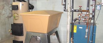
One of the most effective uses of mining is to use it for heating rooms. First of all, we are talking about industrial buildings, workshops, etc. By using such fuel for heating, you can significantly reduce the cost of more conventional energy sources. In fact, waste oil furnaces can completely replace traditional heating systems. In addition, they can be used in conjunction with existing boilers, reducing gas or solid fuel consumption. The advantage of these stoves is that they are able to quickly heat a room.
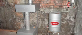
These types of heating devices have different designs, but drip-type furnaces are considered the most effective. This name is explained by the fact that oil enters the combustion chamber in strictly small doses (droplets).
Features of the design of dropper furnaces
Such units consist of a rectangular or cylindrical body. Inside there is a combustion chamber, in the lower part of which there is a container intended for waste oil and holes that provide air flow.
After heating, the fuel evaporates, and then the vapors combine with the air in the chamber. The resulting mixture as a result of convection is directed upward through the firebox, where, when burned, it releases a significant amount of heat.
If desired, a water or air heat exchanger is built into the upper part of the drip furnace during processing, as a result of which it becomes possible to heat the room more evenly and better or to arrange a circuit for supplying hot water.
Drip supply occurs through a metal tube, which is connected to an oil evaporator. Its second end is brought out and connected to the tank with a flexible hose. In the upper compartment of the drip-type furnace during exhaust there is a smoke pipe, which is connected to the chimney.
The temperature in the upper part of the unit, even with a heat exchanger, is not low, so the chimney system must be installed in accordance with fire safety regulations. Experts do not recommend making such a design in an open version, since the oil can ignite.
Babington burner
The Babington burner is different from other waste fuel furnaces. Air under pressure enters the structure, breaking the oil film. This causes the flammable liquid to be sprayed. The air combines with the fuel, and heat is generated as a result of the combustion of the combustible material. The diagram clearly shows the operating principle of this type of furnace.
Babington burner design
To make a Babington burner you will need: • a sprayer; • balloon; • pump; • blowtorch; • container for collecting waste; • splash protection.
The burner is not much like a real stove, but at the same time it effectively heats the room. Some stove elements will need to be assembled by hand. Manufacturing of Babington burner parts:
- The furnace body is made from an empty gas cylinder. The fill funnel must be removed.
- Next, you should make holes for the pipes in place of the funnel. The holes are drilled with a drill in the form of a spiral along the inside. The pipes must be connected to the structure using a welding machine. At the bottom of the pipe, fasteners should be made to attach the sprayer.
- A nozzle, or sprayer, is necessary to capture used oil with air and facilitate the ignition process. The sprayer is best made using a lathe. The base is made from a rod with a smooth shank. Using the nozzle, you can attach the hose to the oil supply. Half of the rod must be made with a metric thread. The pipe should have a diameter of 16 millimeters. It is necessary to drill a hole along the entire length of the nozzle, which will connect to the transverse part. It is advisable to protect the junction of the nozzle and the hose from ignition using a steel screen.
- In order for fuel to mix with air, it is necessary to place a hemisphere at the end of the fuel tube. Both a door handle and a bolt with a spherical head will do. A small hole is drilled in the center of the sphere, through which contact will be made.
- The fuel sump should be made with a special pipe through which the oil will be returned to the main fuel tank.
The design can be complicated by attaching a special valve to control the fuel supply. You also need to make sure the quality of the oven assembly. To prevent oil from leaking in the Babington burner, the device must be made completely sealed.
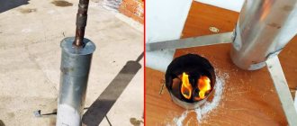
Babington burner in action
Don't rush to throw away used oil. With a few simple designs you can make a high-quality heating device. The stove can be used to heat small spaces, as well as as a source of heat outdoors. The only disadvantage of the product is the unpleasant smell, because the combustion product is spent fuel. It is also worth considering that a homemade waste oil stove needs constant monitoring, as it is a fire hazard.
What are dropper stoves made of?
Due to the fact that this type of unit has a simple structure, you can assemble a drip-type stove with your own hands from a sheet of iron, a gas cylinder and a used barrel. The only requirement for them is the presence of a wall with a thickness of at least 4 millimeters, otherwise the body will move during operation. A proven drawing of a furnace using a gas cylinder will help you assemble the furnace correctly and quickly.
The simplest and at the same time reliable way is to assemble a stove from a gas cylinder, since it has a durable body and can withstand high pressure and heat to high temperatures.
In addition, its dimensions are suitable for a unit capable of heating a garage, workshop or small country house. If you carefully weld such a stove, it will turn out to be safe, it can be easily cleaned and heated.
Differences and features
The main difference between a drip furnace and similar coolants operating on waste oil is that inside the fuel chamber there is a perforated pipe through which combustion air is supplied. The oil flows through the oil pipeline, which then drips into the combustion tank. Preheating occurs using a fuel tube installed in the afterburner. Such a stove operates either due to draft in the chimney or with the help of a fan, which increases heat transfer without increasing fuel consumption. The diagram shows how a drip furnace works:
Since fuel is supplied to the bowl in small doses, and the pipe with holes is in an iron casing, a drip-type furnace can be considered a completely safe device to operate. It also has a number of undeniable advantages:
- No more than 1.5 liters of fuel are consumed in one hour
- Antifreeze or water can be added to the oil
- Fuel is burned efficiently, as evidenced by the smokeless exhaust to the outside
- For forced air injection there are no special requirements for the height of the chimney
- No smoke in the room
Some owners prefer to add additional elements to the standard design to increase the level of safety or turn it into a boiler. You can also weld a furnace with a water circuit in the form of a coil, so that heat is sent to several registers at the same time.
Materials
To assemble a drip furnace with your own hands, you need to prepare:
- used 50-liter gas cylinder with a whole body;
- a two-meter metal pipe with a diameter of 100 millimeters with a wall thickness of at least 3.5 millimeters;
- for the heat exchanger and other small parts - the remains of an equal-flange metal corner with a thickness of 40–50 millimeters;
- a sheet of 4 mm steel or its trim of the required size;
- cast iron brake disc from a car, can be used;
- a regular-sized freon bottle with a needle valve;
- half-meter half-inch metal pipe;
- a hose of the required size, which is suitable for attaching to a ½-inch pipe and clamps;
- half-inch ball valve;
- door hinges and fire door latch.
In addition, pipes of a certain cross-section and a duct fan are needed to assemble an air heat exchanger. You can use a corrugated pipe or components for the chimney. To ensure a high-quality result, you should use drawings of a stove from a gas cylinder during testing.
Repair and maintenance
The fireplace requires regular care: it is necessary to periodically tidy up the ash pan and clean it. The chimney should be cleaned three times a year, as recommended by specialists. You can invite a chimney sweep or handle it yourself.
Restoring brick fireplaces is a complex and expensive process; it is easier to clean the structure once a season than to contact a specialist and waste precious time and money.
Work on preparing the cylinder
Even after prolonged ventilation, condensation remains in the gas cylinder. To remove it, you need to remove the valve and gearbox and leave it in fresh air for several days.
Then a hole is drilled in the bottom of the cylinder. To prevent sparking, the drill is moistened with oil. Since it is not easy to make a hole in thick metal, it is better to start the work with a small diameter drill, and then it can be increased to 10–16 millimeters.
Next, the balloon is filled with water and drained after 24 hours. Since condensate has an unpleasant, pungent odor, it should be carefully poured away from your home. The procedure is repeated if necessary.
Connecting the structure in the bath
The stove design includes a part of the chimney with many holes (usually up to 50). This part of the unit is called the burner. In such a burner, oil vapors are mixed with oxygen entering the smoke exhaust pipe under the influence of draft. As a result of their mixing, the combustion process begins to be much cleaner and more intense, releasing a huge amount of heat.
The tray was made from a cast iron automobile brake disc. Cast iron has good heat resistance, so I decided to use it.
I will make a pallet from this disk
I welded the bottom underneath.
The steel circle is the bottom
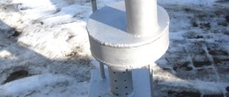
I welded the lid on top. In it you can see the counterpart of the burner and the opening. Air enters the stove through the opening. I made it wide - it's better that way. With a narrow opening, the air draft may not be strong enough, which is why the oil will not be able to get into the pan.
Next I made a coupling. In my stove it connects the pan and the burner. With a coupling it will be much easier to maintain the stove. If necessary, I can take out the tray and clean the burner from below.
Next I made a coupling
The coupling was made from a 10-centimeter pipe, simply cutting it along the longitudinal edge. I did not weld the opening in the coupling - there is no need for this.
The ancestor of such stoves was kerogas, known to the older generation. It differed significantly from other designs in its safety and efficiency. Since the fuel vapors were burned in a special chamber, the entire volume did not heat up and did not create a danger of ignition and fire.
The operating principle of a waste oil furnace is approximately the same. It consists of two containers located one above the other, between which there is a combustion chamber with holes for air intake. The waste is poured into the lower container, the vapors of which actively burn in the middle chamber, and combustion products, smoke and other substances enter the upper chamber connected to the chimney, from where they are removed naturally.
The hot water boiler is located at the top of the stove. It is non-removable and has taps for drawing water into the bathhouse and for starting the heating circuit. The steam room is heated from a brick wall facing inside. To maximize its effect, it is necessary to make the distance from the stove to the brick box quite small to reduce heat loss, but also sufficient for air penetration.
There is another option for making a structure using mining, combined with a brick kiln. Only the lower reservoir is manufactured. The combustion chamber has the shape of an elbow, smoothly bent at 90°. A vertical plate is welded to the end, which communicates with the internal (furnace) part of a conventional brick oven. The hot gases generated during the combustion of waste enter the brick stove and heat it.
The further design is no different from the usual one: a water boiler is installed, a heating circuit with natural or forced circulation, shut-off valves, and so on are connected. This compact option is optimal for those who already have a ready-made furnace and only want to adapt it for burning waste.
The best option: creating a closed heating circuit with a hot water mixing unit. The coolant is heated in a heat exchanger installed inside the boiler or, alternatively, on the chimney. Such a system allows you to cut off the carrier from water for household needs, ensure a more uniform temperature in the system and makes it possible to accurately regulate the temperature in the rooms.
The opportunity to save money on the most expensive area is very attractive for any homeowner, and combining all elements into a single system contributes to more convenient and efficient control of home heating. In addition, the process of recycling used oil is complicated, and the ability to burn it with maximum benefit will be the best option for recycling unnecessary substances.
Stove body
A drawing will help you create a furnace using a gas cylinder.
The work is performed in a certain sequence:
- The balloon is visually divided into two parts, the upper one should be 2/3 of the height, and the lower one should be 1/3. Openings are cut out in each, the width of which is approximately equal to 1/4 of the circle.
- To make holes, use a grinder. You need to make the cut as even as possible. Subsequently, pieces of metal are used to make doors.
- To remove any remaining condensation, the cylinder is additionally washed from a hose with water under pressure.
- The dropper furnace compartments are separated during processing using a metal insert. It is cut to the size of the cylinder from sheet steel.
- The resulting circle will serve as the bottom for the exhaust vapor combustion chamber. It will be large in volume, which will allow you to use firewood or briquettes to fire the unit and, if necessary, burn household waste in it. The bottom is tried on and adjusted to the desired size.
- To make the burner, a 20-centimeter piece of pipe with a cross-section of 100 millimeters is used. Holes with a diameter of 10 millimeters are made in it using a drill and a metal drill. They need to be staggered around the entire circumference to the middle of the burner. The inside of the pipe is polished without leaving burrs.
- The burner is placed in the bottom of the upper part, having welded the joint with a welding machine.
- The completed part is mounted in the unit body between the chambers with the perforated part downwards. The holes are needed for air suction.
- To make a working tray that serves as the bottom of the lower chamber, use a brake disc of the required size. A plug cut from a 4-mm sheet of metal is welded to its bottom to close the hole.
- The top cover with an opening is made from the same sheet. Its shape should allow the counterpart of the burner to be welded, providing air access.
- When assembling a drip-type furnace with your own hands, the bottom of the burner from a piece of 100 mm pipe 10 centimeters long is connected to the lid by welding.
- To connect the parts of the burner, use a coupling, which you can make yourself from a 100 mm pipe, cut lengthwise and slightly bent. The coupling allows you to make the burner detachable. It will be possible to lift it, remove the pan, clean it of oil and remove soot from the top of the chamber and burner.
Making a simple potbelly stove during mining
Potbelly stoves at work
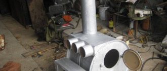
In order for the furnace to last longer during testing, it is better to use thick-walled metal for its manufacture - 6 mm thick for the upper chamber, which heats up more strongly, and 4 mm sheets for the remaining parts. If you don’t have sheets of the appropriate size on hand, you can use old gas cylinders or barrels to assemble the stove.
- The dimensions of the product are arbitrary. For example, a stove measuring 75x35x50 cm will be able to heat a room up to 120-130 cubic meters. m
- The volume of both chambers must be equal. There is no need to make them too large, otherwise the hot gas will immediately cool down. 10-30 l is enough
- The standard width of the chambers is 30-40 cm. The height should be small - 10-15 cm
- The pipe connecting the chambers is made perforated. The distance between the holes is 7-10 cm. Their diameter should be 10-16 mm. Pipe length depending on the volume of the chambers 35-65 cm
- The number of holes directly depends on the length of the pipe. Their area should be equal to 10% of the total surface. The ratio of its length to diameter is 4:1
- To prevent the metal from deforming when overheated, it is better to connect the chambers together with a thick rod to reduce the load on the pipe
- The oven also includes a damper to regulate the air supply. When igniting it, open it completely, and after boiling the oil, turn it off. Most often, such a valve is combined with an oil filling hole.
- To ensure sufficient airflow, the stove is installed on legs. Floors in utility rooms are rarely too level, so it is better to make the legs adjustable. They can be replaced with bricks held together with mortar.
- To avoid fire hazards, there should be no distortions - the stove is installed strictly horizontally, checking its location with the building level
- Due to the small weight of the product (it is about 30 kg), there is a high probability of tipping over. Therefore, it is better to screw the legs to the floor
If the oven begins to smoke, try adjusting the air supply position. If this does not help, there may be a serious mistake in the design of the furnace.
TOP 10 Best gas heaters: making the right choice | Rating 2022 + Reviews
Waste oil supply
Fuel is supplied to the self-assembled drip furnace during production from an external tank using an adjustable dropper. In this case, it is used as a used freon cylinder, which must have a working needle valve.
The sequence of the process of how to make a drip for a stove is as follows:
- In the freon cylinder, in the lower compartment, a hole is made of such a size that it is convenient to pour waste into the structure from any container. If desired, a coarse mesh is placed on it. The tank must be located above the unit, so a special bracket is welded to its body. The hose is connected to the cylinder valve with a clamp.
- A hole is cut out in the housing on the mounting side of the oil tank; its diameter should correspond to a half-inch pipe for feeding waste, which will need to be fixed.
- Having cut a piece of pipe of a certain length, a thread is cut at one end, and the other is cut off under such a knot so that a stream of oil falls directly into the opening of the pan.
- The pipe is welded to the body, and the resulting seam is cleaned.
- A ball valve is screwed onto the end of the threaded tube. During the assembly process, a squeegee with an oil hose is connected to it.
Design and principle of operation of the heating device
It is based on the operating principle of kerosene gas. This is a heating device that uses kerosene and air vapor to produce thermal energy.
The heating device consists of the following blocks:
- Bottom compartment. Welded from 4 mm sheet steel. Must have a round shape. Through the damper, air flows in, which is needed for the combustion process. If the door is completely closed, the combustion will gradually stop.
- Cover with hole.
- Middle compartment. This is a perforated pipe. Holes are necessary for unlimited air flow. To make this and other parts, metal 5.5 mm or thicker is used.
- Top compartment.
- Chimney. Serves to remove combustion products. The length of the pipe is from 4 meters, optimally 5–7 meters. Inclined sections up to 45 °C are allowed, increasing the efficiency of heating equipment. But the greater the slope, the more soot will settle. There should be no horizontal sections; the upper part is directed only vertically. To make this part of the furnace, fireproof materials are taken - tin, copper, stainless steel. The chimney is installed in the upper part of the housing. It is advisable that it be separated - this simplifies maintenance.
The parts are welded together with a continuous seam.
Furnace diagram
The heating efficiency is increased by the blower system. Also, small pipes are welded to the top of the pipe connecting the upper and lower chambers. At the same time, heat transfer increases, and the upper chamber heats up less. Also, vertical ribs are sometimes welded onto the upper module.
The installation works like this. Oil is poured into the lower compartment and set on fire using a wick. After the top layer boils, steam ignites. Turbulence is created, replacing the throttle and swirling the gases. This way, burning vapors enter the perforated chamber, where oxidation occurs under the influence of oxygen. In this chamber the temperature reaches 800°C or more. Nitrogen becomes more active than oxygen, and many toxic compounds of nitrogen and carbon arise.
Standard and modernized furnace model with welded fins and pipes
In the upper part, the pyrolysis residues are finally burned out. Here the temperature drops sharply, nitrogen loses activity and is replaced by oxygen. Therefore, harmless nitrogen gas and steam come out of the heating device, and solid carbon monoxide compounds partially settle inside the chimney.
Heat exchanger
For a drip-type furnace, this element is not mandatory. When the room is small and without partitions, then the heat coming from its walls is sufficient for heating. If it is necessary to achieve greater efficiency of the unit, an air or water type heat exchanger is made. It is placed in the upper chamber.
A heat exchanger is made from a section of 100 mm pipe. Its length should be such that the ends protrude beyond the walls of the housing by 10–20 centimeters on both sides. Two holes are created at opposite ends of the cylinder, a pipe is passed through them and fixed by welding.
A flame divider made of a sheet of iron must be welded above the heat exchanger so that it divides the flame into tongues, increasing heat transfer.
A swirler is placed inside the air heat exchanger, accelerating the air flow. It is made from a strip of steel or a corner divided into bent blades.
Then air ducts made from an uninsulated chimney pipe and corners are connected to the heat exchanger pipe. A duct fan is installed on one side of the air duct. It is connected to the network directly or through the contacts of a thermal relay installed on the fan housing, or by adjusting the temperature mode.
Example of calculating furnace dimensions
As mentioned above, fuel consumption is about 1...2 liters per hour. At the same time, the radiated heat is about 11 kW/hour per liter. Thus, the furnace can produce 11...22 kW per hour. To calculate the required volume of the firebox taking into account the burning time, we accept:
- volume of the room (garage) – 7x4x2.5=70 cubic meters, area 28 sq.m.;
- We believe that for every square meter of a garage-type room, at least 500 W are required (basic 100 W, we enter coefficients for all external walls, non-insulated roof and foundation, large entrance opening, metal structure);
- Accordingly, an area of 28 squares requires 14 kW of energy per hour.
By slightly increasing the minimum power of the stove (increasing the draft), we will obtain the required temperature in the room. But fuel consumption will increase to approximately 1.5...1.6 liters per hour. Therefore, for a burning time of at least 6 hours, the volume of the firebox should be 10 liters. This corresponds to 0.001 cubic meters, that is, the container should have a size, for example, 10x10x10 cm. In reality, the volume of the firebox exceeds the required volume of fuel by 1.5...2 times, that is, the dimensions should be 20x10x10 cm or more, this is suitable for a mini stove. Usually they take it with a substantial reserve, that is, 50x30x15 cm. This allows you not to add fuel every time you ignite.
Important: with large firebox sizes, it becomes necessary to extinguish the fire in the furnace during exhaust before the fuel burns out completely. The extinguishing process is shown in the video.. https://www.youtube.com/embed/5wOBsR2-Xcc
The length of the pipe is 40 cm, respectively, its diameter is 10 cm. The area of the lateral surface of the cylinder is equal to its height multiplied by the circumference of the base (diameter multiplied by the number π), in our case 40x3.14x10 = 1256 cm2. Accordingly, the area of all holes is one tenth of the total - 125.6 cm2. Considering that the area of one hole with a diameter of 10 mm is equal to πx0.52=3.14x0.25=0.78 sq.cm, such a pipe will require 125.6/0.78=160 holes.
Note! The accepted value is the area of the holes 10% of the total area of the side surface of the pipe - conditionally! The number of holes during manufacturing is taken, among other things, from the strength of the product and is usually noticeably less!
Considering that the unfolded cylinder is a 31x40 cm rectangle, and the holes should be placed in a checkerboard pattern, we will have to make 12 vertical rows of 13 or 14 holes each. Marking vertical rows is simple - divide the upper or lower circumference of the base of the pipe into 12 parts in any geometric way and draw vertical drilling lines.
The distance between the rows will be 3.3 cm. Marking the vertical rows is a little more difficult, since in every second row it is necessary to shift the upper (or lower) marking point by half the distance between the holes. Considering that we need to make holes not on the edge of the pipe, we add 1 to the planned number of holes and calculate the step: for 13 holes it will be 40/(13+1)=2.85 cm, for 14 – 40/(14+1) =2.6 cm.
Important: when drilling, the axis of the drill must be directed towards the axis of the pipe!
Ignition and operation
It is not easy to light a cold drip stove during testing. The fact is that oil vapors can only burn when heated, so the unit is ignited using other flammable substances - alcohol or gasoline. They need to be poured into a pan in a thin layer on top of the oil and then set on fire.
When burning, the substance heats up the top layer of waste, and it evaporates. After this, the oven begins to function. Then open the valve on the waste supply hose and adjust its flow into the furnace. To stop the unit, close the valve.
To clean the structure from soot and soot, use metal brushes or fine gravel, which is thrown into the chimney. He, touching the walls of the chimney, knocks off the soot and it settles inside the firebox. After opening the door, sweep it out with a brush. The pan is removed and dirt is cleaned from it.
How to properly make such a hearth can be seen in the drawing of a drip furnace during development, which must be prepared before starting work.
How to light a stove
When starting the device, you need to pour a small amount of fuel into the pan. Then take a piece of foam rubber, well moistened with gasoline, solvent or white spirit, and place it directly in the oil in the pan. The foam rubber is set on fire. When the stand is already warm enough, you can turn on the fuel supply from the cylinder. The valve must be opened slowly so that the fuel gradually flows into the stove. Gradually the unit warms up to operating temperature. It is necessary to ensure that no unburned oil remains in the pan: the supply must be adjusted so that the fuel burns out completely.
To stop the furnace, you must first close the valve on the oil cylinder, then the emergency valve. It will take a few more minutes for the fuel to burn out in the stove, after which the operation of the device will stop completely.
Advantages and disadvantages of the unit
A device that runs on machine oil is especially popular in car service centers, where there is always an excess of this raw material.
Advantages of the heating device during testing:
- As a result of engine oil combustion, soot and fumes are not formed;
- the device is fireproof, since it is not the oil itself that burns, but its vapor;
- the raw materials for operating the furnace cost nothing; they can be obtained at any service station.
Oil heater device
Helpful information! Many car repair shops that use other types of heating are happy to get rid of waste stock, since it is difficult to recycle.
Disadvantages of using mining:
- before use, the waste must be cleaned of impurities of water and alcohol, otherwise the nozzles of the unit may become clogged;
- mining cannot be stored in the cold, so it will have to be kept in a warm garage or in a specially prepared bunker.
Security measures
It is important to remember that a waste oil stove is a device that, if safety precautions are not followed, can cause harm to property and human health. This is why you should:
- Do not use acetone, gasoline or other flammable liquids as fuel. Failure to comply with this rule may result in the device exploding.
- Remove all furniture and textiles from the stove. There should be nothing within a meter radius of the stove that could easily catch fire.
- Do not use the stove without a chimney, with closed air intakes, or leave it unattended for a long time.
You should not trust children or people who do not know how to use the unit to ignite and add fuel.
- It is not recommended to fill the stove with water to extinguish the flame.
Helpful information! To independently extinguish a fire, you can prepare a solution of twenty-five liters of water, eight kilograms of salt and four and a half kilograms of ammonia. This mixture is stored in hermetically sealed half-liter bottles. In the event of an emergency fire, bottles are thrown forcefully into the fire zone so that they break. The gas formed from the mixture will extinguish the fire.
Manufacturing options
Attention: Before manufacturing a drip-type furnace for mining, you should decide in advance on its design. Quite often its basis is a gas cylinder.
During manufacturing, it should be taken into account that its burner is characterized by poor sensitivity to all impurities that are part of used oil. At the same time, the sensitivity of the drip mechanism is very high and should be reduced to the required level. To achieve this, you need to put a filter on the hose, for example, a car filter.
A pump will also be required. A high-pressure fuel pump or a car pump is suitable for this purpose. It will be necessary to make a return flow, since otherwise more oil will flow into the tank than required. This is where a dropper, for example a medical one, comes in handy. Since it has a clamp, it will be possible to regulate the intensity of the fuel supply.
Preparation and production
Having decided to make a similar structure in your garage, you need to draw up a careful drawing of it and prepare the necessary materials and tools:
- IV;
- steel sheet;
- grinder;
- oil container;
- chimney pipe;
- pump;
- gas cylinder;
- welding machine.
It is best to use a gas cylinder with thick metal walls to make such a stove. Of course, you can use sheet steel, but you must first find one that will have the required thickness, and then give it the required shape. And this will require welding work, which will make the manufacturing process more labor-intensive.
When making this design, you should also remember about the presence of a damper to regulate the oxygen supply in the first chamber. Only if it is present will the camera function properly. You need to draw up in advance or find a drawing on the Internet according to which you will make the stove.
Attention: It must be completely vertical and have no horizontal sections, as this complicates its cleaning and impairs traction. The pipe must be made of high-quality material, which will increase its service life.
