When operating the water heater, emergency situations may arise due to incorrect connection of the system or technical defects. To ensure reliable operation, a safety valve is inserted into the system. It guarantees reliable operation of the boiler and protection from damage in the event of a sudden change in pressure due to malfunction.
Boiler safety valve Source santechniki.com
How does pressure release occur?
According to data from the book Calculation and design of pipeline fittings, the valve operation process can be divided into 5 stages:
- The first stage – the pressure is normal
The pressure in the object and in the valve is equal to the working pressure, and the valve is closed tightly. - Stage two – pressure increases
The pressure increases to Value P=K0P0, where K0 is the valve overload coefficient; P0 is the nominal (initial) pressure in the installation. In this case, the force in the spring is equal to the force from the medium pressure. Due to the disappearance of the force interaction between the sealing rings, intense leakage of the medium occurs in the absence of visible movement of the valve disc. - The third stage – pressure increase
The pressure of the medium increases above K0P0, the valve plate rises above the seat and the passage of excess medium begins. As the pressure increases, the valve disc moves upward and the flow rate increases. - Stage four - pressure release
With the release, the pressure in the object decreases and reaches a value at which the valve disc seats on the seat. This pressure is usually lower than the pressure at which the poppet begins to rise and depends on the design of the relief valve. The valve plate sits on the seat; as the pressure decreases, the tightness of the valve lock increases and the leakage of the medium decreases. - Fifth stage - closing the valve
When operating pressure is reached, the valve closes tightly and media leakage is reduced. Watch a video of the lever valve operating and setting
Operating principle
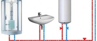
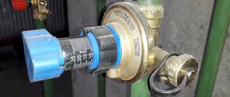
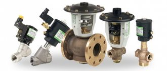
Most ordinary users faced with closed water heating systems are familiar with only one type of safety valve - a simple spring valve with a fixed setting, shown in the photo. The reason is clear - these elements are installed everywhere on any boilers, since they are part of the safety group along with a pressure gauge and an air vent.
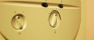
Note. Wall-mounted heat generators operating on electricity and natural gas are equipped with safety elements from the factory. They are placed inside the case and are not visible from the outside.
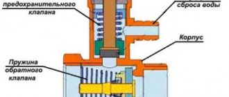
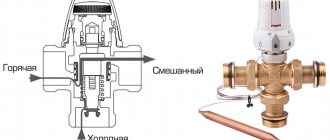
Let's understand how a regular emergency valve works, shown in the diagram above:
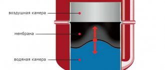
- Under normal conditions, the diaphragm, attached to the stem and supported by a spring, sits tightly in the seat and seals the passage.
- If the coolant overheats, it expands and creates excess pressure in a closed system, partially compensated by the expansion tank.
- When the amount of water pressure reaches the valve response threshold (usually 3 Bar), the spring is compressed under its influence and the membrane opens the passage. The boiling coolant is automatically discharged until the spring has enough strength to close the flow area again.
- In the event of an emergency, the owner of the house can relieve excess pressure himself by turning the handle at the top of the product.
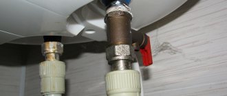
A few words about where the relief valve is installed along with the safety group in a closed heating system. Its place is on the supply line in the immediate vicinity of the boiler (recommended no further than 0.5 m).
The safety unit is always installed on the heater flow line
Important point. It is prohibited to install taps, valves and other shut-off devices on the pipeline leading from the heat generator to the safety elements.
You should not tightly connect the pipe of the product to the sewer - wet spots or puddles will indicate the valve has been activated and problems in the heating network. For example, the expansion tank failed or the circulation pump malfunctioned when working with a solid fuel boiler (the electricity may have been turned off). Often the device begins to leak due to debris getting between the seat and the plate. More about his work is described in the video:
Additional information. Masters and installers call spring relief valves blasting valves because the pressure of the coolant compresses the spring and causes the membrane to explode. Do not confuse them with explosive elements installed on the chimneys of industrial boiler houses that burn natural gas.
How spring safety valves work
In spring-loaded valves, the pressure of the medium on the valve is opposed by the degree of compression of the spring. It is this that determines the actuation force, and the range of adjustments depends on the elasticity of the spring used.
The coolant exerts pressure on the spring, which compresses. When the set pressure is exceeded, the spool rises and the coolant is discharged through the outlet pipe. After the pressure in the system has dropped to the set pressure, the valve closes and the coolant drainage stops.
The response pressure of the spring safety valve is set by equipping the valve with various springs.
Many valves are manufactured with a special mechanism (lever, fungus, etc.) for manual detonation for control purging of the valve. This is done in order to check the functionality of the valve, since various problems may arise during operation, such as sticking or freezing of the spool to the seat.
Valve without manual release
Select valve
Manual release valve
With manual detonation
However, in industries using aggressive and toxic environments, high temperatures and pressures, control blowing can be very dangerous. Therefore, for spring valves used in such industries, the possibility of manual blowing is not provided and is even prohibited.
Video of the operation of a spring safety valve from the StroyNefteGaz channel
The spring safety valve is available in three versions:
- Low-lift devices are suitable for gas and steam pipeline systems, the pressure in which does not exceed 0.6 MPa. The lifting height of such a valve does not reach more than 1/20 of the seat diameter
- Medium-lift devices in which the spool lift height is from 1/6 to 1/10 of the nozzle diameter.
- Full-lift devices in which the valve lift height reaches up to ¼ of the seat diameter.
Recommendations for selection
Quality emergency relief valves are rarely cheap, as they are made from bronze, brass or stainless steel. The main thing is to make sure that there is a normal price-quality ratio.
It is possible to select the simplest option, which costs little, but is problematic to check regularly.
A pressure gauge, which helps monitor the condition of equipment, increases costs but improves safety.
A bellows valve will help make a small heating system autonomous.
It is important that the main mechanism is sufficiently reliable, but not very elastic, and that the adjustment is convenient. It is necessary to immediately check the correspondence of the diameter of the fuse and the pipe coming from the boiler so that you do not have to change the part.
If the pipes are of small diameter, then ball or disc equipment will be sufficient. The gravity valve is mounted only in a horizontal position, and the main valve is always made of a petal type.
It is necessary to install several air vents if a boiler or riser is used. With a water type of heating, an expander is placed at the highest point, which replaces several air vents. But this option complicates maintenance and takes up a lot of space.
Control valves are selected based on the degree of comfort expected and the expected service life of the heating system. When set to the minimum settings, the noise level is reduced, and in a situation with water heating, the formation of rust is prevented. Reinforcing elements reduce the load and increase the service life of the circulation pump.
When the coolant is oil, or the heating is working well, a bypass valve is installed, which operates constantly, reliably providing the required level of protection.
The safety relief valve for the boiler is equipped with a special numerical marking with the letters atm, which indicates what pressure a particular product can withstand in order to work properly.
The usual set pressure for a household fuse is 3 atm. The preload is only 1.5 atm, and the operating pressure at maximum temperatures reaches 2.5 atm. This means that if the indicated parameters are exceeded, the situation becomes emergency and the valve must operate.
For high-quality products, the minimum strength index is 4 atm, which is sometimes exceeded when manually pouring heating fluid.
The safety control valve stabilizes the entire system at a safe level.
The reduction model normalizes the force of coolant inflow by adjusting the internal cross-section of the inlet part of the pipeline.
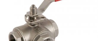
The lever-load variation assumes use for large pipeline lines with a large cross-section; it includes a spool that opens the shut-off valve. The mechanism is triggered when the pressure level exceeds the weight of the weights hung on the handle.
In closed systems, a pressure valve is sometimes installed, the degree of operation of which is manually adjusted. With the help of an adjustable thermal head and mechanical action on it, it is very convenient to adjust the operation via a servo drive.
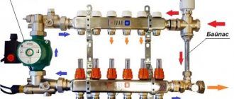
The bypass product reduces the load from the coolant and stabilizes the heating functionality. It is installed instead of a relief valve: the temperature is built up in the return pipeline, after which the excess liquid is returned back to the common line. Now the pressure is already regulated.
The part is placed behind the circulation pump and connected simultaneously to the supply and return pipes.
How does the TKZ safety valve work?
Spring-loaded safety valves are full-lift, direct-acting.
Full lift is ensured due to the dynamic effect of the energy of the steam jet on the damper bushing (12). The outlet passage of the valve in operating condition is closed by the plate (4) by the compression force of the spring (3), slightly greater than the pressure of the medium on the plate from below.
When the pressure of the medium under the plate increases above that adjusted on the valve, the plate begins to rise. The flowing medium acts on the damper bushing causing a sharp rise of the plate to a height of 0.25d.
The damper bushing extends outwards and is secured to the rod (5) with a special locking screw (13) to prevent it from being unscrewed.
In order to prevent unauthorized changes in the tension of the spring (4), a protective cap is provided that covers the pressure sleeve (9) and the end of the lever (10).
For manual testing of valves under pressure, a lever (10) is provided.
valves
For steam boilers
- For steam boilers
- For hot water
Dn50Pn64
Compare
Close
Valves T-31MS Du50
TKZ
₽49,400.00
| General characteristics | |||||||||||||||||||||||||||||||||||||||||||||||||||||||||
| Dimensions | |||||||||||||||||||||||||||||||||||||||||||||||||||||||||
| |||||||||||||||||||||||||||||||||||||||||||||||||||||||||
Rules and standards
The use of safety valves is regulated by national and industry standards, operating rules and technical instructions.
For pressure vessels, the following regulatory documents apply:
- (PB 03-576-03). Safety rules for pressure vessels and installations.
- "Boiler & Pressure Vessel Code" American standard.
- GOST 24570-81 National standard for safety valves.
Download GOST 24570-81
Systems protected by emergency valves, in the event of abnormal operation or an accident, pose a significant threat to industrial and public safety. Therefore, their design, configuration, installation, and operation are supervised by authorized bodies that monitor compliance with the requirements of rules and standards at all stages of the equipment life cycle. In the Russian Federation, this is entrusted to Rostekhnadzor.
Magnetic spring safety valves
Magnetic spring safety valves use an electromagnetic actuator. The electromagnet provides additional pressing of the spool to the seat.
When the response pressure is reached, the electromagnet turns off and only the spring counteracts the pressure, and the valve begins to operate like a regular spring valve. Also, the electromagnet can create an opening force, that is, counteract the spring and force the valve to open.
There are valves in which the electromagnetic drive provides both additional pressing and opening force; in this case, the spring serves as a safety net in case of power failure.
Magnetic spring valves are typically used in complex impulse safety devices as control or impulse valves.
Selecting a boiler via a virtual network
Today there is no particular need to go somewhere and choose something. This applies not only to primary goods, but even to construction and heating equipment. Today you can easily place an order through an online heating boiler store. It will give you the opportunity to view what models are available and compare their characteristics. Usually the assortment is quite diverse, and heating boilers are available not only from domestic manufacturers, but also models that are in demand in Europe and Asia.
For those who value their time, purchasing heating boilers through an online store is a significant time saver. If the boiler you have chosen is large in size or includes a large number of parts that are quite difficult to transport on your own, then again you should contact the online store. In this case, the boiler will be delivered to the location you need without any hassle.
What to do if water drips through the relief valve
The nature of the problem depends on whether the water from the safety valve is dripping or flowing in a stream.
If the coolant is dripping, this indicates normal operation of the emergency valves, but the heating system is operating at the limit, since the temperature in the coolant in it is increased and the pressure exceeds the norm. It’s easy to check whether the drops are the natural operation of the mechanism - just lower the operating temperature, allowing the coolant to cool. If the water drainage stops, then everything is in order, you just need to prevent further reheating.
A mechanism clogged due to contaminated coolant. Particles of sand and dirt prevent the rod from completely closing, which causes leakage.
If the drops do not stop or the coolant is discharged in large quantities, in a stream, this indicates a malfunction of the safety valve: the spring, rubber or silicone seal are worn out, the fitting is clogged, as a result of which it does not fit tightly. It is not recommended to disassemble the mechanism yourself; in this case, it is necessary to replace the relief valve (issue price 400-900 rubles).