The change in pressure during thermal expansion without taking into account the deformation of the system elements can be calculated using the formula: Δp = βt · Δt / βv, where βt is the coefficient of thermal expansion of water, 1/°C; Δt – change in water temperature, °C; βv – coefficient of volumetric compression of water, 1/Pa. Calculations show that in a rigid closed system, the pressure change is about 3 bar/°C. If we take into account pipe deformations, the results will be as follows:
|
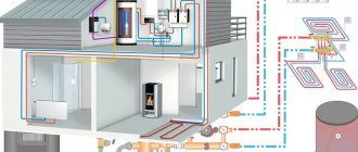
How does the VALTEC expansion tank work? The expansion membrane tank contains a diaphragm that divides it into two parts, one of which contains nitrogen, which is under initial excess pressure, and the other part receives excess coolant from the system.
Initially, the entire volume of the expansion tank is completely occupied by nitrogen; When the coolant is heated, its volume increases, which leads to nitrogen compression. The pressure of the nitrogen blanket increases and equalizes the pressure in the heating system at a given static level. When the temperature of the coolant and, accordingly, its volume decreases, the pressure of the nitrogen blanket returns the coolant back into the system, preventing the pressure in the system from falling below the set level.
| Under operating conditions, the inner surface of the membrane expansion tank body is often an area of possible condensation. If there is oxygen in the gas cushion, intense corrosion of the metal of the tank body will inevitably begin. That is why manufacturers pump neutral nitrogen into the tank, and not atmospheric air containing water vapor and oxygen. By pumping air into the gas cavity, the user unwittingly shortens the service life of the membrane tank. |
Connection point of the VALTEC expansion membrane tank to the heating system
The pressure at the point of connection of the membrane tank to the system is always equal to the static pressure at a given point at given temperature parameters.
| Proving the above statement is very simple. If we assume that the pressure at the tank connection point changes, then we will have to admit that the volume of coolant in the tank has also changed. But this cannot be, because... There was nowhere for excess coolant to come from in a closed system, and there was no way it could disappear without a trace either. It should be noted that this rule only applies to a system with one expansion tank. |
Thus, the operating parameters of all other elements of the heating system, the required initial pressure in the expansion tank and the volume of the tank itself depend on the location of the expansion tank.
| When choosing the location for connecting the expansion tank, remember that the higher the pressure in the heating system, the less likely it is to become airborne. |
| If the membrane tank is connected to the system directly after the circulation pump, you should check that an anti-cavitation pressure reserve is maintained in front of the pump. |
In Fig. 1 shows several options for connecting a membrane tank to a heating system with the following height parameters:
- excess of the top point of the system over the bottom (H) – 10 m;
- the heat generator and safety valve are located 2 m above the lowest point of the system (h1);
- the expansion tank is placed 1 m above the point of its connection to the system (h2);
- static pressure at the lowest point of the system is 15 m of water. Art.
Rice. 1. Options for connecting the membrane tank to the heating system
At the remote flags in Fig. 1 indicates the calculated values of operating pressure at characteristic points of each system (in m of water column).
The safety valve setting value is assumed to be 33 m water. Art., pump pressure – 6 m water. Art., system capacity – 200 l. The difference between the maximum and minimum temperatures of the coolant is 80 ºС.
In table 1 shows the calculated characteristics of membrane tanks for circuits with their different connections.
Table 1. Calculated data for systems in Figure 1
| Scheme in Fig. 1 | Estimated preliminary pressure in the tank, m water. Art. | Estimated tank capacity, l | Brand of selected tank VALTEC |
| A | 13 | 14,9 | VRV18 |
| b | 13 | 14,9 | VRV18 |
| c | 11 | 14,2 | VRV18 |
| d | 11 | 14,2 | VRV18 |
| e | 3 | 11,5 | VRV12 |
| f | 3 | 11,5 | VRV12 |
| When installing a membrane tank in a gravity heating system on the upper line, it should be shifted from the main riser towards the heating risers in order to eliminate the parasitic effect on the circulation of the coolant cooling in the tank. The main riser must be equipped with an air vent and a safety valve (Fig. 1f). |
The coolant must enter the membrane tank from above. In this case, there is no chance of air getting into the liquid compartment of the tank. If this requirement cannot be met, it is recommended to follow these rules:
Rice. 2. Options for organizing the release of air from a system with a membrane tank |
Selection of VALTEC membrane expansion tank
It is recommended to determine the sufficient volume of the membrane expansion tank using the formula:
Vb = C βt / (1 – Pamin / Pamax), (1)
where C is the total volume of coolant in the heating system, l. Includes the volume of water in pipes, boiler, radiators and other elements of the system. This indicator is calculated based on the actual capacity of each element of the system; Pamin – initial (setting) absolute pressure in the expansion tank, bar ; Pamax – maximum absolute pressure possible in the expansion tank, bar.
With a certain error, the value of the coolant volume in the system can be selected from the table. 2. When making calculations at the feasibility study stage, it is allowed to assume a specific capacity of the heating system of 15 l/kW.
The values of the coefficient of thermal expansion of the coolant βt, corresponding to the maximum difference in water temperatures in an idle and operating system, are recommended to be taken from the table. 3.
The setting absolute pressure is calculated using the formula:
Pamin = Pa0 + Pstmax – 0.1· (NB + h2 + 1), (2)
where Pa0 – atmospheric pressure, bar; Pstmax – static pressure at the level of the lowest point of the system, bar; NB – the excess of the tank insertion point above the lowest point of the system, m; h2 – height of the tank center above the insertion point, m.
When the tank is located below the insertion point, h2 is inserted with a minus sign.
Absolute maximum pressure possible in the expansion tank:
Pamax = Pa0 + PPC + PstB – PstPK – 0.1 h2, (3)
where PPK – safety valve setting pressure, bar; PstB – static pressure at the safety valve installation level, bar; PstPK – static pressure at the level of insertion into the membrane tank system, bar.
Table 2. Approximate volume of coolant in the system
| Type of system and its elements | Specific volume of coolant, l/kW | Notes |
| Boiler room | 13 | excluding the volume of storage tanks |
| Heating system | 11 | average value |
| Heating system convectors | 8 | |
| Convectors ventilation systems | 10 | |
| Heating system radiators | 15 |
Table 3. Value of the coefficient of thermal expansion of coolants βt
| Temperature, °C | Glycol content, % | |||||||
| 0 | 10 | 20 | 30 | 40 | 50 | 70 | 90 | |
| 0 | 0,0002 | 0,0032 | 0,0064 | 0,0096 | 0,0128 | 0,0160 | 0,0224 | 0,0288 |
| 10 | 0,0004 | 0,0034 | 0,0066 | 0,0098 | 0,0130 | 0,0162 | 0,0226 | 0,0290 |
| 20 | 0,0018 | 0,0048 | 0,0080 | 0,0112 | 0,0144 | 0,0176 | 0,0240 | 0,0304 |
| 30 | 0,0044 | 0,0074 | 0,0106 | 0,0138 | 0,0170 | 0,0202 | 0,0266 | 0,0330 |
| 40 | 0,0079 | 0,0109 | 0,0141 | 0,0173 | 0,0205 | 0,0237 | 0,0301 | 0,0365 |
| 50 | 0,0121 | 0,0151 | 0,0183 | 0,0215 | 0,0247 | 0,0279 | 0,0343 | 0,0407 |
| 60 | 0,0171 | 0,0201 | 0,0232 | 0,0263 | 0,0294 | 0,0325 | 0,0387 | 0,0449 |
| 70 | 0,0228 | 0,0258 | 0,0288 | 0,0318 | 0,0348 | 0,0378 | 0,0438 | 0,0498 |
| 80 | 0,0290 | 0,0320 | 0,0349 | 0,0378 | 0,0407 | 0,0436 | 0,0494 | 0,0552 |
| 90 | 0,0359 | 0,0389 | 0,0417 | 0,0445 | 0,0473 | 0,0501 | 0,0557 | 0,0613 |
| 100 | 0,0435 | 0,0465 | 0,0491 | 0.0517 | 0,0543 | 0,0569 | 0,0621 | 0,0673 |
| 110 | 0,0515 | 0,0545 | 0,0568 | 0,0591 | 0,0614 | 0,0637 | 0,0683 | 0,0729 |
| 120 | 0,0603 | 0,0633 | 0,0653 | 0,0673 | 0,0693 | 0,0713 | 0,0753 | 0,0793 |
| As the analysis of formula 1 shows, the optimal choice of the volume of the expansion membrane tank is directly related to the correct setting of the safety valve (according to SP 41-101-95 “Design of heating points”, this is a mandatory element for the expansion tank). Usually it is set to a pressure that exceeds the permissible value for the most vulnerable element of the system by 10% (taking into account the difference in height of the valve and the protected element). Therefore, for heating systems it is recommended to use valves with the ability to adjust the setting pressure. In addition, the valve must have a forced opening (“undermining”) device to periodically check its performance and to avoid sticking of the spool. An example of such a valve is shown in Fig. 3.Fig. 3. Safety valve VALTEC VT.1831 with the possibility of adjustment and forced “undermining” |
Installing an expansion tank of insufficient volume or incorrect installation can cause the heating system to malfunction and even fail.
The tank setting pressure should not be lower than the hydrostatic pressure at the center of the tank by more than 1 m of water. Art. (0.1 bar). Otherwise, already in the process of filling the system, the useful volume of the tank will be filled with coolant, and with subsequent heating and expansion of the liquid, a smaller volume will be provided than necessary. In other words, if the set (factory) pressure in the tank is 1.5 bar, then the system must be filled to a pressure at the center of the tank that does not exceed 1.6 bar. If according to the project it is necessary to install a higher hydrostatic pressure in the system, then for this, before installing the tank, it is necessary to increase the pressure in it using an air pump.
| A certain amount of coolant in the tank, ensured that it is “under-pumped” to hydrostatic by 1 m of water. Art., is necessary in case cooling of the filled coolant occurs. For example, if the system was filled during the day at a water temperature of 20 ° C, and the boiler was not started for some reason, when the coolant cools at night, its volume will decrease, which can lead to a vacuum at the upper points of the system and intensive air suction through the air vents. |
In two identical systems that differ only in the type of coolant, a larger expansion tank will be required in the system that uses a non-freezing coolant based on glycol (ethylene or propylene glycol), because
The expansion coefficient of glycol solutions is slightly higher than that of water. Thus, when switching from a water system to a glycol system, it may be necessary to replace the tank with a larger one or install an additional expansion tank.
A signal that the system needs a larger tank is the frequent operation of the safety valve.
| The diameter of the supply line to the membrane expansion tank must be no less than calculated using the following formula: where Q is the boiler power, W; Vk – volume of water in the boiler, l, s – heat capacity of the coolant J/kg K. |
Calculation methods
Each installation is selected in accordance with the size of the expected load, which will require preliminary calculations. Knowing how to calculate the volume, the owner will be able to choose the right tank.
To choose the right expander, you will need to know:
- heating boiler volume;
- additional devices;
- all pipes included in this heating system.
Next, let’s designate the required indicators with any letters, for example, A is the desired value, B is the efficiency of the membrane equipment, C is the constant expansion rate of the coolant water, and AO is the total volume of the heating system. Next, we calculate using the following formula: A = (AO * C) / B.
Sizing
The final value is rarely absolutely accurate, so approximate calculations are made, and the resulting number will be a guideline for choosing a unit, which should be taken with a margin to the obtained number, leaving at least 3% for the increase in volume during heating.
If a membrane type has been selected, the operating potential of the membrane may be indicated by the manufacturer, but you can make your own calculation. To do this, take the most permitted indicator of pressure inside the system (AB), data on the pressure of the initial filling of the expander (BC) and calculate the desired value (T). Use the following formula: T = (AB – BC) / (AB + 1).
If you do not make calculations and take the equipment “at random,” you may encounter some problems during operation of the device. The main purpose of the expander is to pump out excess liquid with a strong increase in pressure (moisture expands, requiring the excess to be removed from the pipeline). After everything has stabilized, the liquid is compressed back, it must be returned to the pipes, otherwise there will not be enough of it to maintain the temperature. Therefore, identifying differences in the internal pressure of the heating system indicates an imminent breakdown.
Tank too small
If the volume of the installed expander is insufficient, the pressure will increase too much and the automatic valve will operate. It will remove excess moisture, stabilizing the operation of the system. But then everything will return to normal, and the water will no longer be enough to continue proper heating. Additional refueling will be required. A lack of heating fluid will lead to the boiler shutting down, since at low levels the device cannot continue to function. Because of this, pipes may freeze in winter. Breakdowns will occur again and again until the optimal size expander is installed.
Excessively large tank
Installing a tank that is too large is also dangerous. When taking part of the moisture from the pipes, the expander must maintain the optimal permissible operating pressure, which is simply impossible if the dimensions are too large. The unit will constantly show the maximum permissible load without crossing the very line when the valve should operate. This means that the device operates at its maximum potential level, which will quickly lead to breakdown.
Examples of piping with membrane tanks
Rice. 4. Installation of an expansion tank in a system with one boiler: 1 – expansion tank; 2 – safety valve; 3 – circulation pump; 4 – filter; 5 – check valve; 6 – shut-off valve; 7 – air vent
In this case, the expansion valve is located on the return pipeline of the system, which allows it to be operated at a lower coolant temperature than if it were installed on the supply line. This solution allows you to extend the service life of the device. Connecting a tank to the pump suction pipe protects the pump from cavitation.
Rice. 5. Installation of expansion tanks in a system with several boilers and automatic limitation of the minimum water temperature in the return pipeline (one tank is provided for each boiler): 1 – expansion tank; 2 – safety group (safety valve, pressure gauge, air vent); 3 – circulation pump; 4 – three-way mixing valve; 5 – check valve; 6 – shut-off valve; 7 – hydraulic arrow
This scheme provides for one expansion chamber per boiler. The capacity of each of them must be no less than that calculated for the entire system, i.e. if according to calculations she needs a tank with a capacity of 80 liters, then this should be the capacity of each of the installed devices. This is due to the fact that when operating at reduced power, when the burner of one of the boilers is turned off, the corresponding circulation pump also turns off and the three-way valve closes. In this case, there is no water circulation through the disconnected boiler, and the expansion tank installed on this boiler is isolated from the rest of the system. The expansion chamber remaining in operation must provide compensation for the expansion of the coolant throughout the entire volume of the system. This provision is also true when using two-way valves that perform the function of blocking boilers.
Rice. 6. Installation of an expansion tank in a system with several boilers and automatic limitation of the minimum water temperature in the return pipeline (one expansion tank for the entire system): 1 – expansion tank; 2 – safety group (safety valve, pressure gauge, air vent); 3 – circulation pump; 4 – three-way mixing valve; 5 – check valve; 6 – shut-off valve; 7 – hydraulic shooter
To what level should the air chamber be inflated?
It is important to correctly configure the expansion tank for closed-type heating. Calculating capacity is, of course, a serious aspect, but even if done correctly, the tank may still not function properly. To understand this, let’s briefly look at its design. It consists of two compartments, between which there is a rubber gasket. There is no connection between cameras. There is a nipple in the air compartment.
During operation, water fills the volume of the tank chamber, while the membrane stretches. If the pressure in the air chamber is too high, it will simply prevent the elastic from deforming. As a result, the tank does not work. The air chamber should be two tenths of an atmosphere less than the operating pressure of the boiler. Or use the manufacturer's recommendations to configure.
Membrane tanks for hot water systems
The main difference between membrane tanks for water supply is that the water in them should not come into contact with the walls of the housing, as is allowed in heating systems. Therefore, they always use a chamber-type membrane (in the form of a bag). In addition, the membrane material of water supply tanks is subject to increased requirements regarding the permissibility of contact with food liquids.
The calculation of a membrane expansion tank for domestic hot water is carried out according to formula 1. The volume of water in the system is calculated taking into account the water contained in the pipelines and the water heater or heat exchanger.
| The design of some water heaters provides for the presence of a damping air cushion in the closed volume of the water heater itself. The volume of this pillow is determined by the height of the DHW outlet pipe and should also be taken into account when selecting a DHW expansion tank. |
An example of installing a membrane tank for domestic hot water is shown in Fig.
7. Fig. 7. Installation of an expansion tank in the hot water supply system: 1 – expansion tank; 2 – safety valve; 3 – pump; 4 – filter; 5 – check valve; 6 – shut-off valve
Online calculator
The third way to perform calculations is an online calculator. On the Internet you can find several different programs that simplify the question of how to choose the volume of the expansion tank. Information about coefficients and the dependence of the desired value on temperatures or pressure in communications is already included here.
Our website provides a program for determining the capacity of a closed tank. Here, the adjusted gas pressure refers to the minimum limit that is typical for a heating boiler. For example, if it is 1.5 Atm, then there should be the same amount in the tank. The safety valve is often set to the maximum pressure in the line or equipment. The third thing you need to know is the volume of the coolant.
There are two advantages to working with online calculators, and they are significant:
- immediate results;
- accounting for tabular data that the user does not need to search for.
However, there are also disadvantages. Here it is impossible to track what exactly was taken into account by the developers to produce a particular result. The result can also be considered as close to the exact one.
FAQ
http-equiv=”Content-Type” content=”text/html;″>class=”reviewsblock”>
How does the size of the house affect the amount of storage needed? The volume of the house does not affect in any way, the efficiency of the heating system and the power of the boiler do. After all, variables such as the required heat for heating per hour and the difference between supply and return are precisely indicators of the quality of your system.
The better the heat accumulator is insulated, the more efficiently it will work? According to installation requirements, such a container should only be located in a room with a positive temperature. In this case, standard insulation 10 cm thick will be sufficient. There are cases when such containers are buried in the ground to store more energy, but further maintenance of the system becomes very difficult.
Is this container only suitable for heating? It can be used in several ways. To provide a heating system or hot water. A solid fuel boiler or an electric boiler can be used as a source (an example operating at night with a two-zone meter installed and a preferential tariff). When using a solar collector, solar panels or a wind generator. View all construction myths
The best known manufacturers and models: characteristics and prices
Sunsystem PS 200
A standard inexpensive heat accumulator, perfect for a solid fuel boiler in a small private house with an area of up to 100-120 m2. By design, this is a regular tank, without heat exchangers. The capacity of the container is 200 l at a maximum permissible pressure of 3 bar. For a low cost, the model has a 50 mm layer of polyurethane thermal insulation and the ability to connect a heating element.
Price: on average 30,000 rubles.
Hajdu AQ PT 500 C
One of the best buffer tank models for its price, equipped with one built-in heat exchanger. Volume – 500 l, permissible pressure – 3 bar. An excellent option for a house with an area of 150-300 m2 with a large power reserve of a solid fuel boiler. The line includes models of different sizes.
Starting with a volume of 500 l, models (optional) are equipped with a layer of polyurethane thermal insulation + an artificial leather casing. Installation of heating elements is possible. The model is known for extremely positive reviews from owners, reliability and durability. Country of origin: Hungary.
Cost: 36,000 rub.
S-TANK AT PRESTIGE 300
Another inexpensive buffer tank with a capacity of 300 liters. The design is a storage tank without additional heat exchangers with a maximum permissible operating pressure of 6 bar. The internal walls, as in previous cases, are made of carbon steel. The main difference is a significant, environmentally friendly layer of thermal insulation made of polyester material using NOFIRE technology, i.e. high class thermal and fire resistance. Country of origin: Belarus
Cost: 39,000 rub.
ACV (ATsV) LCA 750 1 CO TP
A productive, expensive buffer tank with a volume of 750 liters with an additional tubular heat exchanger for domestic hot water, designed for boilers with a large power reserve.
The internal walls are covered with protective enamel and there is a high-quality 100 mm layer of thermal insulation. A magnesium anode is installed inside the tank, which prevents the accumulation of a layer of solid salts (the kit includes 3 spare anodes). It is possible to install heating elements and additional instrumentation. Country of origin: Belgium.
Cost: 168,000 rub.
Coefficient of increase in volume of water/water-glycol mixture depending on temperature
As is known from the laws of physics, all liquids expand when heated (as, indeed, do any bodies). This fact must be taken into account when calculating the volume of the expansion tank.
Water increases in volume when heated to 950C by 4%. This statement is quite accurate, so it can be used in calculations without fear.
If a water-glycol mixture is used as a coolant, the picture changes somewhat, depending on the ethylene glycol content.
Expansion tank in the heating system
In this case, the expansion coefficient of the working fluid is determined as follows:
- 4% x 1.1 = 4.4% – with an ethylene glycol content of 10% of the total coolant volume;
- 4% x 1.2 = 4.8% – if the volume of ethylene glycol in the mixture is 20%, etc.
The above values will vary depending on the temperature to which the coolant is heated. For example, at 80 degrees the coefficient of expansion of water will be 0.0290. If 10 percent of its volume is replaced with ethylene glycol, the coefficient will be equal to 0.0320. A mixture of glycol half and half with water (50%) is characterized by an expansion coefficient of 0.0436.
Installation
Installation diagram of a tank in a private house system
If you are confident in the calculations and your own abilities, the tank and all materials have been purchased, then you can install the container yourself.
Tools you will need:
- Step and adjustable wrenches;
- Soldering device for plastic pipes;
- Wrench for installing plastic pipes;
- In some cases, a welding machine and an angle grinder are needed.
Before installation, you need to turn off the power to the boiler, turn off the valves and drain the coolant if it is already in the pipes.
The installation is carried out taking into account certain rules.
- The tank must be mounted and installed so that it can be easily approached for adjustment and maintenance.
- The room temperature should not be below 0.
- A pre-shut-off valve must be installed on the supply pipe, which will allow the expander to be removed for maintenance and repair.
After installing the tank, you need to start the entire heating system. If boiling is detected in it, then the reason lies in the incorrectly selected pipe diameter. It's not about the tank. The installation of the expansion tank is described in the following video:
Principle of operation
From the physics course we know that fluid is incompressible.
In the heating circuit, water is used as a coolant.
In the temperature range from 20 to 90 degrees, it changes volume, expanding as it heats up.
If we imagine a heating network as a vessel of complex configuration, then heating the contents will cause the walls to rupture due to expansion of the liquid.
To compensate for this phenomenon, an expansion tank is used, which serves as an additional volume for storing excess coolant.
Having expanded, the water enters the tank, and when cooled (approximate prices for a heating cable for water supply) it goes back into the system.
It is simply impossible to remove excess water, since when it cools, air will fill the void and the circuit will cease to function.
Do you know what to do if water flows from the tank into the toilet. Read this useful article for tips and recommendations from master plumbers on troubleshooting.
The scope of application of asbestos-cement pipes measuring 150 mm is written on this page.
Thus, the expansion tank protects the heating system from both excess and shortage of coolant, compensating for all movements of its volume.