The stove is considered a traditional design for heating buildings.
But if it is installed in a large house with several floors, then its power may not be enough to heat all rooms evenly. The solution here may be a furnace coil, which is also called a heat exchanger. It is connected to a heating device, then it is carried out through each room, thereby ensuring ideal and uniform heating of the entire building.
Design features
Most often, a metal tank with a capacity of up to 5 liters with built-in pipes acts as a heat exchanger. There is no direct contact with fire. The device allows you to heat cold water, which then flows into radiators or a removable tank of larger capacity located in the same or an adjacent room.
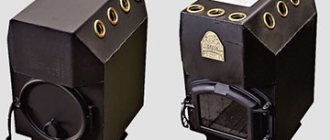
As a result, by heating the stove in one room, it will be possible to heat another. According to its design, the heat exchanger for a furnace can be external or internal.
This type is very similar to a tank filled with coolant. Inside the container there is a part of the pipe used to remove combustion products. In terms of its design, the external heat exchanger is more complex than the internal one, as it places increased demands on welding work.
However, its maintenance is much easier. If necessary, the tank can be dismantled to remove scale or eliminate leaks.
Interior
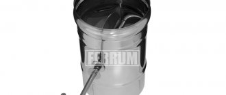
Mounted above the firebox directly inside the stove. It is easy to install, but if maintenance is necessary, certain difficulties may arise. Especially if the stove is made of brick.
To avoid this, at the time of design development it is worth taking care of the maintainability of the future heat exchanger.
Flaws
Despite many advantages, the installation of a heating element on a chimney pipe also has disadvantages . One of them, the most important, is a sharp decrease in the smoke temperature at the installation site of the heat exchanger. This can lead to deterioration of traction and the formation of condensation, increased soot deposition inside the pipe.
In addition, when connecting a heating system, for example, a garage, you need to calculate the volume of coolant to avoid boiling water and bursting pipes . Welds must be completely sealed.
Any heat exchanger design significantly increases the efficiency of the furnace . For trouble-free operation of the system, it is necessary to carry out a visual inspection of all its elements at least twice a year , and, if necessary, timely repairs, descaling, replacement of gaskets and other necessary maintenance work. In this case, water heating and heating systems will operate flawlessly for a long time.
Pros and cons of the oven
A conventional stove distributes heat unevenly: it is very hot right next to the stove, and the further you go, the colder it becomes. The presence of a water circuit allows the heat produced by the stove to be evenly distributed throughout the house.
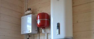
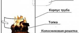
Construction of a heating furnace with a water circuit
Thus, only one stove can heat several rooms in the house at the same time. The stove works almost the same as a solid fuel boiler. Only it doesn’t just heat up the coolant and water circuit. In addition, the walls and smoke channels are heated, which also play an important role in the heating process.
The heat exchanger (coil) is the main element of the stove. It is installed in the fuel part of the stove, and there the entire water heating system is connected to it.
The advantages of a furnace with a water circuit include the following features:
- First of all, for such a furnace there is no need to purchase expensive units and components.
- A properly built stove will serve you for a long time without requiring expensive repairs. Sometimes, you may only need a small cosmetic one.
- The stove can be created in any design: shape, size, decoration - all this is according to your taste and financial capabilities.
- If you compare a stove equipped with a water circuit and a solid fuel boiler, then with the help of the first one heats not only the coolant, but also the smoke outlets.
- The coil can be equipped with an already built stove. It can also be inserted into a cooking stove.
A stove option that fits perfectly into the interior of the room.
This type of heating also has disadvantages.
- When the heat exchanger is inserted into the fuel part, the latter's precious space is greatly reduced. The problem can be solved if the heat exchanger is built into the furnace during its construction. This part just needs to be increased. Well, if it is inserted into an already built structure, then there is no other way out except to add fuel incompletely, but in parts.
- With such a stove, the fire hazard increases. There is an open fire burning in the stove and fireplace, plus spare wood is often stored nearby. Do not leave this unit unattended.
- If the stove is operated incorrectly, carbon monoxide entering the home can lead to very dire consequences.
An image from which it becomes clear that it is better not to leave the unit unattended.
Experts advise using non-freezing liquid in such structures if people do not live in the house permanently, but, for example, only in the summer.
What should you keep in mind?
With natural circulation of the coolant, the heat exchanger should be placed above the furnace at a distance of 1.5 - 2.5 m. Due to the constant change in geometric parameters, the pipes cannot be fastened to the wall tightly enough. It is necessary to provide a small gap.
It is important to remember that if the stove is used not only to heat the house, but also to heat water, a maximum of 10% of the total amount of heat generated should go to the heat exchanger. When using a structure with an expansion tank for heating, the volume of the latter should be selected so that the water in it can heat up to the required temperature in two hours.
The return pipes should have a smaller diameter than the coolant supply pipes. The material intended for sealing threaded connections is selected with a sufficient level of heat resistance.
If the house is not intended for permanent residence, but is used only from time to time, then it is better to refuse water heating. It is advisable to fill in special antifreeze instead of water if you plan to heat a stove with a heat exchanger in the cold season. This will prevent pipes from bursting. Remember that adding coolant when the furnace is fully heated is unacceptable.
Latest announcements
Gas boiler Protherm (Proterm) Bear 20 klom
New in box, everything is sealed, warranty receipt dated 09/1/19. I’m selling because it doesn’t fit our old system, but to return...
- Region: Moscow region
11.09.19
Water heating gas boiler VK-21(KSVA-2.0 GS)
We offer steel water heating boiler KSVa-2.0 Gs (VK-21). For a wholesale order (from 2 boilers) a price discount is possible Type...
- Region: Kirov region
05.08.19
Steam generator KV-300
We offer steam boiler KV-300 (KP-300). Steam capacity for normal steam, kg/hour – 300; - permissible excess...
- Region: Kirov region
28.06.19
Steam generator for 500 kg steam
Technical characteristics: — steam output — 500 kg/h; - boiler type - two-pass, fire-tube with reversible...
- Region: Kirov region
28.06.19
Steam generator for 1600 kg steam
Technical characteristics: — steam output — 1600 kg/h; - boiler type - two-pass, fire-tube with reversible...
- Region: Kirov region
28.06.19
Water heating boiler KSV-0.63
We offer a water heating boiler KSV-0.63. Technical data and characteristics: - rated heating capacity, ...
- Region: Kirov region
28.06.19
Water heating boiler 850 kW gas diesel
Technical characteristics: - nominal heating capacity - 0.85 MW; — Efficiency – 92%; - boiler type - two-pass, ...
- Region: Kirov region
28.06.19
Automatic coal boilers Lugaterm
The boiler model combines three main parts: a water-cooled firebox, a heat exchanger with automatic mechanical ...
- Region: Moscow
15.03.19
SOLID FUEL WATER BOILERS ON THE KVR MINE FIRES
Type of fuel: firewood of any moisture content Power from 0.2 to 2.5 MW Purpose: obtaining hot water at a nominal temperature ...
- Region: Kirov region
05.02.19
WATER HEATING BOILERS FOR WORKING WITH WOOD PROCESSING AND LAWMILLING WASTE KVM
Type of fuel: wood waste (sawdust, wood chips, bark) – without humidity limitation Power: from 0.2 to 2.5 MW Purpose: ...
- Region: Kirov region
05.02.19
Announcements by topic:
- Boilers and equipment for boiler houses
- Cooling towers
- Heat networks (all about pipelines)
- Materials
- Water treatment
- Cogeneration
- Autonomous heat supply
- Pumps, fans, smoke exhausters
- Pipeline accessories
- Heat exchange equipment
- Metering devices
- instrumentation and automation
- Repair equipment
- Heating devices
Advantages
Installing a water circuit in a stove heating system allows you to increase fuel efficiency.
The energy of the burnt coolant is spent on heating the housing, smoke channels and walls, and also ensures the high temperature of the water circulating through the pipes.
For property owners, this method provides additional benefits:
- ease of manufacture (brick stoves are often installed in residential buildings, and for high-quality energy distribution it is enough to make a homemade heat exchanger by connecting it to the heating system of the building);
- combined heating using warm air from the stove and hot water from the radiators;
- variety of types of fuel (most heating boilers use only one type of energy carrier, which can be expensive and ineffective, and the heat exchanger of a brick kiln works using any solid fuel);
- pleasant appearance (the design of a country house is often carried out in the national style, but the installation of heat exchange units does not violate the traditional appearance of the Russian stove).
Design features
If the owner of the building has experience in bricklaying or stove work, the installation can be done with his own hands. Before connecting the water heating system, you will also need to make a heat exchange unit.
Despite the fact that the construction market offers a large selection of ready-made structures, self-production is more profitable. A manual installation allows you to take into account all the parameters of this particular stove, its placement and the dimensions of the fuel compartment.
Heat exchanger made of pipes
The design of a stove heating system with a water circuit involves installing a heat exchanger in the fuel compartment of the stove and connecting pipes to it to supply working fluid. For heating and cooking stoves and cookers, coils welded from pipes and placed in metal containers are well suited. Their production requires professionalism, and cleaning from combustion products is quite labor-intensive, but the tortuous surface will ensure rapid heating.
The 50 mm U-shaped pipes used in the design can be replaced with sections of 40x60 mm profile pipes. This will simplify the welding work and greatly facilitate installation. If the oven is not used for cooking, additional small diameter tubes are welded to the top of the heat exchange unit. The design, improved with your own hands, will give off much more heat.
Sheet steel heat exchanger
Devices of this type are used in furnaces intended exclusively for heating the room. To make them, you will need sheet metal half a centimeter thick, sections of rectangular pipes 40x60 mm, as well as round pipes of the same diameter for supplying water to the working surface. The dimensions of the heat exchangers depend on the size of the furnace fuel compartments.
A similar heating system can be used for a heating and cooking stove or a simple stove. To do this, the structure must be mounted so that the heated gases from the fuel chamber move towards the upper shelf of the register, flow around it and enter the smoke channels.
Installing a heat exchanger on a sauna stove
Since all of the listed models differ significantly in their ability to withstand overheating, the installation location for a specific model is selected based on the design of the firebox and the material from which the heat exchanger is made.
Frame or register systems are typically used in brick sauna stoves. The device is embedded in the upper part of the firebox or in the roof of the furnace during its construction. In this case, the pipes for connecting to the tank are led out from the back or sides of the furnace body.
Flat coils made of copper and stainless steel are installed in the same way. They can be embedded either in the vault or in one of the vertical walls of the combustion chamber in a sauna stove.
Twisted copper coils are traditionally installed on the top chimney. Sometimes the coil is located directly under the top-mounted central hot water tank. The tank heats water for spraying the heater, and the copper heat exchanger heats water for the shower or washing compartment.
Disc and box heat exchangers are installed on one of the side walls in a sauna stove. They are usually used for steel or cast iron stoves. To install, just cut two holes in the wall. After that, spacer bushings are put on the outlet pipes, and the heat exchanger is installed inside the firebox using union nuts. This type of heat exchanger is also called dry, since water does not get inside the combustion chamber under any circumstances.
Important! Box and register heat exchangers are installed inside the sauna stove so as to reduce the contact of the metal surface with the hottest part of the combustion front.
The heat exchanger should receive most of the heat inside the stove not through convection and flow of hot gases, but in the form of infrared radiation from the walls and roof of the sauna stove. To avoid overheating, the heat exchange circuit pipes must be shielded with stainless steel sheets. As a result, the service life increases, and the water in the heat exchanger is heated more evenly, without boiling and steam fountains.
Connection diagram for a heat exchanger for a bath
Almost all models of heat exchange devices operate on the principle of gravity or natural convection of water in a semi-closed pipe system. Therefore, when developing an installation diagram for a heat extraction device, it is necessary to adhere to two rules:
- The inlet and outlet pipes of the heat exchanger must be located at different levels, the vertical distance between the lower and upper water supply points must be at least 20-25 cm. The lower pipe is used for supplying cold water, the upper pipe is used for discharging boiling water;
- Connection to the heating circuit pipes of the sauna stove must be made only using flexible connections, and the couplings must be sealed with heat-resistant silicone.
We are not talking about flexible rubber hoses in a metal braid; they are not suitable for these purposes, even if the label is marked “for hot water” or something similar.
Important! Due to the strong thermal radiation coming from the walls of the sauna stove, the rubber ages and burns out in a matter of weeks.
Experienced users recommend connecting the tank to the heat exchanger in the bath using flexible stainless steel gas hoses.
How to connect a heat exchanger to a sauna tank
The classic installation scheme is a remote tank for a bath with a heat exchanger. This means that a container with hot water for showering and cleaning the room is located either on the nearest wall or outside the steam room, closer to the shower stall.
It is important to ensure a certain height difference between the exit from the heat exchanger of the sauna stove and the bottom of the container with water. Typically this value is selected within the range of 50-70 cm
For box and register circuits, flat coils, the tank is located at a level of 120 cm above the floor level. This is convenient; you can scoop up hot water through the top hatch.
It’s another matter if the heat exchanger coil for the bath is installed on the chimney pipe. In this case, the tank will have to be raised to a height of 180-200 cm, so install a bronze hot water tap at the bottom or at the outlet of the circuit.
The pipelines leading from the heat exchange circuit of the furnace to the tank are usually located at a slope. The cold line from the lower pipe is supplied to the supply tank at a right angle, this ensures the maximum hydrostatic head in the circuit. The outgoing line is installed at an angle of 25-30°. This is done to separate air and steam bubbles formed in the water flow during heating.
On the cold main, be sure to make an elbow and install a drain ball valve, with which you can easily drain the water from the bath heat exchanger.
Inspection of welded joints and bends
Each welded joint is subjected to external inspection and measurement to identify displacement of the edges and fracture at the joint (Fig. 8). The displacement b of the welded edges refers to the parallel displacement of the pipe axes among themselves. Kink k is a deviation in the form of a skew of the axes of the joined pipes. The displacement of the edges and fracture of the joint is measured with a special ruler 400 mm long with a cutout in the middle, which is installed tightly along the generatrix of one of the pipes with a cutout at the joint, and the deviation is determined along the other pipe with a feeler gauge at a distance of 200 mm from the axis of the joint. Measurements are carried out in 3 - 4 places around the circumference of the joint.
The inspection reveals such defects as burning (melting) of pipes in places of contact with the jaws and the machine body, creeping edges, and incomplete removal of the outer burr.
a - displacement; b - fracture;
Figure 8 — Deviation of welded pipe edges
To check the quality of welds, as well as devices for automatic control of welding process parameters, express tests of control welded joints (samples) are carried out. Samples are received before the start of each shift. Welding is allowed to be performed only if there are positive results of express tests of control samples. As a rule, express samples are subjected to metallographic examination.
Checking the mechanical properties and metallographic examination of welded joints is carried out on samples made from control welded joints, or on samples of welded joints cut from the manufactured product. In the case of cutting from finished products, the volume of control joints must be at least 1% (but not less than three joints) of the total number of identical welded joints performed by each welder in one shift.
By running the ball with compressed air, the completeness of removal of internal flash (or metal leakage) is checked - ensuring the specified flow area in welded joints. When inspecting welded joints on straight pipes (braids), a ball with a diameter of 0.86 in.nom is used, on coils 0.8 in.nom. of pipes. The reduction in the diameter of the ball when monitoring the flow area in the coil is caused by the ovality of the pipes in the bends. A ball catcher is placed on the free end of the coil, which ensures safe operation.
Ovality control of pipe bends and heating surface coils is selective (at least 10% of bends of the same standard size). The maximum ovality along the entire bend length should not exceed the permissible value. The maximum and minimum outer diameters of the pipe at the bending point are measured in one control section.
The ovality of the section in places where pipes are bent can be determined
where and are, respectively, the maximum and minimum outer diameter of the pipe at the bending point, measured at one section of the section, m.
Permissible ovality for boiler heating surfaces
where R is the bending radius of the pipe, m;
— outer diameter of the pipe, m.
The thinning of the pipe wall at the bending point on the stretched (outer) side is determined selectively by an ultrasonic thickness gauge. It is recommended to check the thinning when changing bending tools, setting up the machine and accessories.
For pipes with a diameter of up to 60 mm, bent without heating, high frequency currents (HFC), waviness (corrugations) on the inside of the bend and bulges on the stretched side should not exceed 0.5 mm in height with a minimum step of at least three heights.
Installation of a heating device
Heat exchangers for brick stoves can be made with your own hands from metal 2.5 mm thick. The basis of the design will be two containers - a cylindrical upper one and a rectangular lower one, connected to each other using pipes. The joints must be joined with a minimum gap, and the diameter of the pipes must be calculated based on the dimensions of the furnace and the area of the heated room. After checking the accuracy of the calculations and re-measuring the workpieces, the parts are connected by welding.
The strength of the finished structure is determined after welding the lower pipe, pouring water and connecting the outlet holes with the radiator tanks. When installation is completed, it is necessary to fill the system with compressed air, monitoring the pressure using a pressure gauge. Well-welded seams will not leak. If leaks or other defects are detected, the water is drained and problem areas are sealed. An important parameter during installation will be the total length of the pipes - the shorter it is, the better the heating of the room will be.
Choosing material
The coil is traditionally made from a pipe, the length and diameter of which are determined by the desired level of heat transfer. The efficiency of the structure will depend on the thermal conductivity of the material used. The most commonly used pipes are:
- copper with a thermal conductivity coefficient of 380;
- steel with a thermal conductivity coefficient of 50;
- metal-plastic with a thermal conductivity coefficient of 0.3.
Copper or metal-plastic?
With the same level of heat transfer and equal transverse dimensions, the length of metal-plastic pipes will be 11, and steel pipes will be 7 times longer than copper ones.
That is why it is best to use annealed copper pipe to make a coil.
Such a material is characterized by sufficient plasticity, and therefore it can easily be given the desired shape, for example, by bending. The fitting is easily connected to the copper pipe with a thread.
We are looking for improvised means
Considering the high cost of materials, it would be appropriate to consider the possibility of using products that have already served their purpose, but have not yet fully exhausted their service life. This will not only reduce the cost of manufacturing the heat exchanger, but will reduce the time for installation work. As a rule, preference is given to:
- any heating radiators that do not leak;
- heated towel rails;
- radiators from cars and other products of similar design;
- instantaneous water heaters.
Where are coil heat exchangers installed?
The heat transfer method depends on where the coil is installed:
The boiler contains coils with fins.
In the boiler, the flame heats the water in the coil, and then it disperses throughout the entire system, releasing thermal energy into the room by convection through heating radiators. Some of them also fall into the category of coil heat exchangers. For example, heated towel rails and heating registers made of round or profile pipes.
Contact with an open flame imposes certain requirements on the performance of the metal used in production. The emphasis is on reliability and durability. Therefore, steel and cast iron are most often used. The latter is considered the best option.
In a boiler and heat accumulator, heat transfer rate and corrosion resistance are of priority. In this case, there is nothing better than copper. The main thing is that it does not come into contact with aluminum. A reaction occurs between these metals, which leads to chemical corrosion.
Methods for making coils
There are three main schemes for obtaining coils of boiler heating surfaces (Fig. 7): element-by-element, braided and by the method of sequential extension. Regardless of the method, the technological process for manufacturing coils includes: incoming inspection of pipes; sorting the original pipes by length; development of schemes for cutting pipes into elements; pipe cutting, trimming and cleaning of pipe ends. We choose the element-by-element method.
Figure 7. Element-by-element diagram of coil manufacturing
With the element-by-element manufacturing method, prepared straight pipes are first bent on machines followed by plastering, then the bent elements are welded together into a coil (Fig. 7).
Disadvantages of stove heating with a water circuit
- Loss of usable space. A heat exchanger built into the firebox significantly reduces its size, so this factor must be taken into account when laying the firebox. Well, if the heat exchanger is built into an existing structure, the only solution is to frequently add fuel.
- Increased fire hazard. Since a stove or fireplace requires the presence of an open fire and a fuel supply nearby, it is not recommended to leave such a stove unattended for a long time.
Having organized stove heating in the house, you must constantly monitor fire safety
Carbon monoxide. If used incorrectly, carbon monoxide, which is dangerous to human life, can enter residential premises.
Advice. If heating with a water circuit is installed in a country house where no one lives regularly, especially in winter, then in order to avoid freezing of the water in the circuit, it is better to use an antifreeze liquid.
Source of thermal energy for the system
The part of the system that provides the transport function is not of interest to us. The theory of its functioning is needed in order to make heating with your own hands. As a source that would heat the water, you can use a gas boiler or an electric one.
The fireplace as a water heater turns into a multifunctional device. He continues his mission to provide the external decoration of the room and create comfort from the opportunity to contemplate the combustion process, but to warm up all the rooms, they use a fireplace with water heating.
The rather low efficiency index, especially for a fireplace with an open firebox, does not allow us to hope for high-quality heating during periods of severe frost. But for a small house this option is quite suitable. If you provide the ability to connect and disconnect the fireplace from the heating system, then the ideal option can be realized.
Commissioned furnace
The idea is that the main heating is taken over by the device that is intended for this purpose. At the right moment, the fireplace turns on and provides additional energy. At dachas, when the owners leave for a while, the fireplace can be turned off and the main boiler left running.
Let's start installation
The sequence of work depends on the design features of the heat exchanger.
Installation of a device with a register
When installing in an old furnace, you will have to dismantle part of the masonry. The sequence of work is as follows:
- We prepare the foundation for the coil right in the firebox cavity.
- We install the coil.
- We lay the disassembled row of bricks, leaving space for the inlet and outlet parts of the pipes.
- We connect the heat exchanger to the heating system.
Before use, the tank must be checked for leaks. You can make sure there are no leaks by filling it with water, preferably under pressure.
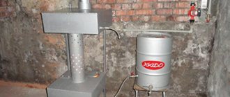
Installation of a device with a container
The best option for a stove or fireplace. Made from a metal tank and two copper tubes. The tank volume is usually about 20 liters. In the absence of a finished product, a tank of sufficient volume is made by hand by welding sheet steel.
For the manufacture of the heat exchanger, a material thicker than 2.5 mm should be used. Welding should be done in such a way that the thickness of the formed seam is minimal.
The tank must be installed 1 meter above the floor level, but no further than 3 meters from the stove. Two holes are made in the tank: one near the bottom, the second at the highest point on the opposite side. The efficiency of heat transfer depends on the location of the lines.
It is necessary to strive to ensure that the minimum deviation of the lower outlet in the direction of the floor is 2 degrees. The top one should be connected at a 20 degree angle in the opposite direction.
The drain valve is being installed in the storage tank. There is another tap designed to drain the entire system, which is installed at the lowest point. After checking the tightness, the system is ready for operation. The efficiency of such a stove with a heat exchanger can be appreciated in the cold season.
Installation and connection
How to mount the heat exchanger is shown in photo No. 1:
Photo No. 1 Connecting the heat exchanger
Photo No. 2 - required slopes and dimensions
Step-by-step instruction:
- Let's determine a suitable location for the remote container. It is hung on the wall, 100-300 mm above the heat exchanger.
- The tank should not be hung directly on the wall of the bathhouse. First, we attach the guides with dowels - 2-3 wooden dies. Then, already on them, we hang the tank. The gap between the wall and the container must be at least 20 mm.
- To strengthen the structure, use special brackets, securing them under the bottom of the container. When assembling the container, do not forget to provide holes through which it will be attached.
- We will need 4 pipes: one for direct supply, the second for reverse supply, the third for filling with cold water, the fourth for the consumer. Place a check valve on the third pipe, and connect the tap and shower to the fourth.
- Using fittings, connect the remaining 2 pipes (forward and return) to the heat exchanger using good copper or steel corrugated pipe. Don't forget to seal all connections.
- We install a valve on the return line to drain the liquid. It must be installed so that it is at the lowest point.
- We attach a low tank with a heat exchanger to the wall of the furnace. How to install a heat exchanger on a sauna stove is shown in photo No. 1, and the necessary slopes are also shown there (photo No. 2). It can be built-in. Work must be carried out in compliance with safety regulations.
- Using fittings, we connect the forward and return supply pipelines.
Do-it-yourself stove heating with a water circuit, step-by-step construction
First, before you start building the stove, you need to prepare the foundation. To do this, you need to dig a pit, the depth of which is 150–200 millimeters. Fill the bottom with layers of broken brick, crushed stone and rubble. Then fill everything with cement mortar. The foundation should rise several centimeters above the floor. Place waterproofing material on the screed.
Construction process of a water loop furnace
Main features of brick laying
The stove must be built from quality materials. Walls can be built from bricks with normal firing, but for the firebox, purchase refractory bricks.
- Before starting laying, the bricks must be wetted. To do this, immerse them in water for a while. When air bubbles stop coming out of them, you can start laying.
- All rows and corners must be tied.
- Apply the cement mortar to the entire rad at once. Its layer should be about 5 millimeters. Refresh the mortar on the end right before laying brick on it.
- When you get to the firebox, don't apply the clay with a trowel. Do it with your hands.
- Every five rows, carefully cut off excess cement from the seams and wipe them with a damp sponge.
- The walls of the stove must be vertical and horizontal. Use a spirit level constantly during laying to check this.
How and how to connect the external tank to the heat exchanger
Remember that the elements in contact with the stove become hot, their surface temperature exceeds 100 0C. Therefore, the pipes must be made of stainless steel (cast iron will not work, as it is susceptible to corrosion). But ordinary pipes are allowed to be made of metal-plastic; they can even be replaced with flexible hoses. The main thing is that the diameter is 1 inch or 3/4, otherwise the circulation will be poor.
Use tangit for seals, and paronite for fittings. Feel free to replace factory elements with non-standard ones, but made of heat-resistant material. Don't forget about the drain valve - it is simply necessary to preserve the system for the cold season or to quickly remove stagnant liquid. Otherwise, during frosts, the remaining water will freeze and burst the pipes.
Application specifics
Standard stove heating implies an uneven distribution of thermal energy - the further from the source, the colder. After connecting the radiators and filling with water, the stoves act as analogues of solid fuel boilers, providing heating of the coolant, smoke channels and walls. During combustion, such a system will allow heat to be transferred from the coil to the radiators, and after the fuel dies out, it will use the energy of the heated walls of the furnace.
When installing a heat exchanger, it is worth considering that its installation will reduce the usable volume of the fuel compartment and fuel will have to be added much more often. Correct design of the water circuit and its relationship with the dimensions of the heating chamber will help eliminate this problem. A good alternative would be to install a long-burning stove.
Such an upgrade of the heating system has its own nuances. The energy released during the combustion of wood will heat the heat exchange unit and the working fluid placed in it, but the walls of the furnace will not change their temperature.
The upper part of the housing with the smoke channels will be heated. If the building is used for temporary residence, the furnace will be turned on irregularly and can lead to freezing of the liquid inside the pipes. In order to prevent accidents, it is recommended to replace water with antifreeze.
Principle of operation
Modern heat exchangers may differ from each other in the principle of heating water, on the basis of which they can be divided into several types:
- Coil installed inside the heater;
- An external heat exchanger, made in the form of a rectangular tank, the heating of which is ensured by contact with the walls of the furnace;
- An external water circuit whose high heating temperature is maintained by flue gases.
You can also find models on sale in which a stainless steel water tank is already installed in the design. However, this type of heat exchanger works in the same way as a coil.
Coil
The first type of air heat exchanger for the chimney is a steel coil, which is installed directly in the firebox. It is positioned in such a way as to avoid direct contact of the pipe with the flame. In other words, it is installed at some distance from the highest temperature zone. It is best when this element is located in the path of waste products of fuel combustion. In this case, you won’t have to worry about its possible burnout, and this is a guarantee of its long service life. The built-in coil has connections at the outlet that allow you to connect pipes leading to an external storage tank.
The advantage of heat exchangers of this type is the minimum time for heating water. However, their performance is not impressive.
- For heating, heat taken from the firebox is used, and this leads to a decrease in the heater power. As a result, the heating time of the steam room increases, and this increases fuel consumption.
- The main problem remains unresolved - the hot flue gases will continue to fly out into the chimney in the same way, without bringing any benefit. Because of this, the efficiency of the unit is at a rather low level, which does not exceed 50%.
True, all of the above does not apply to brick sauna stoves equipped with a heat exchanger and several flue gas passages, which serve to maintain a comfortable temperature in the dressing room and washing room.
Outdoor heat exchanger
Another type of chimney heat exchanger, which allows the heat of the stove to be transferred to water, is an external hanging tank made of stainless steel. As a rule, it is installed on one of the side walls of the firebox, and heating is provided by the infrared radiation emitted by it. The advantage of this option is ease of installation, but using such a heat exchanger is not very convenient. Here the disadvantage inherent in the first type of heat exchanger manifests itself, namely, straight-line heat extraction, and in addition to this, cold water has to be constantly added to the hanging tank.
Quality indicators
Quality indicators serve to evaluate the operational merits of the unit, the main ones being: technical level, reliability and durability, structural, aesthetic and ergonomic characteristics of the unit.
A. Technical level.
There are absolute, relative and long-term technical levels.
The absolute technical level of a product is characterized by its performance indicators. Their number should be minimal. In order to avoid multiplicity and vagueness in assessing the absolute level, it is necessary to limit ourselves to only the most important of them - productivity, efficiency, process continuity, degree of automation.
The relative technical level characterizes the degree of perfection of a product when comparing (according to relevant indicators) its absolute technical level with the level of the best modern world - domestic and foreign - samples and models of similar purposes.
The promising technical level determines the intended and planned trends in the development of a given industry in the form of a set of its promising indicators.
B. Durability and reliability.
These indicators are the most important of the quality indicators.
Durability is the ability of a unit to remain operational with as few interruptions as possible for maintenance and repairs until destruction or another limiting state. The main quantitative indicators of durability are technical resource and service life.
Technical resource - the total operating time of the unit during the period of operation.
Service life is the calendar duration of operation of the unit until destruction or to another limiting state (for example, until the first major overhaul). The service life is limited by the physical and moral wear and tear of the unit.
Reliability is a property of a unit, determined by the reliability, durability and maintainability of the unit. Quantitative indicators of reliability: operating time, probability of failure-free operation, availability factor.
Running time is the duration or volume of operation of a unit, measured by the number of cycles, the number of manufactured products, or other units.
The probability of failure-free operation is the probability that, under certain modes and operating conditions, no failure occurs within a given operating time. Availability factor is the ratio of the operating time of the unit in units of time over a certain period of operation to the sum of this operating time and the time spent on finding and eliminating failures during the same period of operation.
B. Ergonomics and technical aesthetics.
Creation of modern heat exchangers that meet the best designs and international standards in terms of quality, ease of maintenance and appearance. The design of an industrial heat exchanger must be based on technical specifications and, at the same time, on the requirements put forward by new scientific disciplines - ergonomics and technical aesthetics.
Ergonomics is a scientific discipline that studies the functional capabilities of a person in labor processes in order to create perfect tools and optimal working conditions for him. Technical aesthetics is a scientific discipline, the subject of which is the field of activity of the artist-designer. The goal of artistic design is (in close connection with technical design) the creation of industrial facilities that best meet the needs of operating personnel, that best meet the operating conditions, have high aesthetic qualities, and are in harmony with the environment and setting.
A beautiful appearance usually corresponds to a rational and economical design. The appearance of the product largely depends on its color. Color is the most important factor, not only determining the aesthetic level of production, but also influencing worker fatigue, labor productivity and product quality.
Furnace heat exchangers
Coil arrangement diagram
The diagram shows one of the coil options. This type of exchanger is good to place in heating and cooking stoves, because its structure easily allows you to place a stove on top.
In order to reduce the labor intensity of the manufacturing process, you can make a few changes to this design and replace the upper and lower U-shaped pipes with a profile pipe. In addition, vertical pipes are also replaced with rectangular profiles if necessary.
If a coil of a similar design is installed in ovens where there is no hob, then to increase the efficiency of the exchanger, it is advisable to add several horizontal pipes. Treatment and removal of water can be done from different sides, it depends on the design of the furnace and the design of the water circuit.
How to make a screw coil
After you have made the calculation of the heat exchanger coil, you can proceed directly to manufacturing. The screw design is quite simple to make. The diameter of the loop must be selected based on the size of the tank into which installation will be carried out. It is necessary that the pipes do not touch the body.
Today, the cheapest insulation for walls is mineral wool. At the same time, it is also one of the best options.
Having compared the characteristics of insulation, the superiority of polymers becomes obvious.
You need to wind the turns onto a round blank. Copper bends easily, so no additional tools are needed. It is advisable to maintain a small space between the turns so that the coolant is in contact with the pipe on all sides. This will increase the heat exchange area, which will allow us to achieve the maximum thermal power that we calculated.
Economic indicators
A. Thermohydrodynamic perfection.
The power spent on pumping coolants in the heat exchanger determines to a large extent the heat transfer coefficient, i.e., the overall heating performance of the device. Therefore, an important indicator of the perfection of a heat exchanger is the degree to which power is used to pump coolant to ensure the required heat exchange.
The thermohydrodynamic perfection of the apparatus can be characterized by the ratio of two types of energy: heat Q transferred through the heat exchange surface, and work N spent on overcoming hydrodynamic resistance and expressed in the same units for all flows. Thus, the measure of the use of work expended on heat transfer can be expressed by the relation
E = Q/N
The greater the value of E, the more perfect, other things being equal, the heat exchanger or its heat exchange surface from a thermohydrodynamic (energy) point of view. The energy coefficient E is a dimensionless quantity, therefore the numerator and denominator of the expression E = Q/N can be referred to an arbitrary, but the same unit, for example, to a unit of heat exchange surface (thermal indicator), to a unit of mass of the heat exchange surface (mass indicator) or to unit of volume (volume indicator). When comparing apparatuses, the value of E can be related to all heat and to all work expended, or to a unit of surface, mass or volume of the apparatus.
The analysis shows that, all other things being equal, a change in the coolant speed has different effects on various quantities characterizing the operation of the heat exchanger: the heat transfer coefficient changes proportionally to the speed (or flow rate) to the power of 0.6-0.8, the hydrodynamic resistance is proportional to the speed to the power 1.7-1.8, and the power for pumping coolant is to the power of 2.75.
With an increase in the speed of the coolant, the power to pump it grows much faster than the amount of heat transferred, i.e. for a certain apparatus or a certain heat exchange surface, the value of the energy coefficient E decreases with increasing speed of the coolant. Therefore, the absolute value of the coefficient E cannot serve as a measure of the thermohydrodynamic perfection of a heat exchange apparatus, but is useful only when comparing two or more apparatuses.
B. Efficiency.
The thermal indicator of the perfection of a heat exchanger is its efficiency coefficient (efficiency):
n=Q2/Q1
where Q1 is the maximum possible amount of heat that can be transferred from a hot coolant to a cold one under given conditions; Q2 is the amount of heat transferred from the hot coolant to the cold one, or the heat expended in the technological process.
The maximum possible amount of heat, or available heat, depends on the initial temperatures and water equivalents of the coolants.
General information about pipe-in-pipe heat exchanger
With the help of heat exchangers, or heat exchangers, thermal energy is exchanged between two substances used as a coolant. This leads to heating of one of them and cooling of the other. Based on this ability, some heat exchangers on heat pipes act as heaters, others as refrigerators.
The method of heat transfer by devices can be:
- Superficial. Serves to separate the coolant. In this case, a special wall is provided that conducts heat well between the two compartments of the tank.
- Regenerative. The heat transfer procedure includes two stages, during which a special nozzle is alternately heated and cooled.
- Mixing. For heat exchange between two media, their direct contact and mixing are used.
How to install a water circuit
Installation occurs in the same way as installation with any other heating system. The only point that needs to be taken into account is that the “return” for stove heating is located higher.
There are three types of coolant circulation:
- Natural. For natural circulation, pipe installation must be carried out at the maximum permissible slope. In addition, in the place where the pipe leaves the furnace, it is necessary to install an “acceleration manifold”: for this, the pipe is directed vertically to a height of 1–1.5 m, and then down to the radiators at an angle.
Forced. This type of circulation increases efficiency by up to 30%. A circular pump is added to the circuit, which creates coolant pressure. However, it is undesirable to arrange a system with only one type of forced circulation, because in the event of power outages or pump failure, water will not circulate, which will lead to boiling of the coolant in the system.
Combined. For this type of circulation, it is necessary to combine the installation of pipes with a slope, as described in the first paragraph, with the pump. In this case, the pump is connected to the system via a parallel line, as indicated in Diagram 4. With this combination, the pump will operate in the presence of electricity; in its absence, circulation will occur naturally.
Conclusion
Installing a heat exchanger on a sauna stove does not require much work. To do this, just follow the instructions above. The main principle is compliance with slopes. Photo No. 1 shows one of the heat exchanger options for a bath and its installation. Otherwise, problems will arise with the pressure. When organizing water heating, you should adhere to the following rules:
- The length of the forward and return pipes should not exceed three meters.
- The remote tank is placed at such a height that the slopes are maintained. The excess must be at least 100 mm.
- Pipes for the heat exchanger of a sauna stove for heating water must be made of stainless steel or copper.
- The water in the system must not be allowed to freeze; it must be drained after each use of the steam room. A special valve is provided for this. It also serves as an emergency drain if an accident occurs.
- The power should be selected so that the device heats the required amount of water to +70C in 2 hours. The liquid in the system should not boil. Scale quickly damages the device.
- The diameter of the pipelines should not be less than 24 mm.
By following these simple rules, you will always have hot water and save money on installing an electric boiler.