Potapov's vortex heat generator, or VTP for short, was designed specifically to generate thermal energy using just an electric motor and a pump. This device is used primarily as an economical heat source.
Today we will look at the design features of this device, as well as how to make a vortex heat generator with your own hands.
- 1 Operating principle
- 2 What is it used for?
- 3 Tools needed
- 4 Manufacturing technology. Engine
- 5 Install the pump
- 6 Increase productivity
- 7 We insulate the VTP
- 8 Vortex damper
Download the VTG assembly manual in .PDF format
A little history
The vortex thermal generator is considered a promising and innovative development. Meanwhile, the technology is not new, since almost 100 years ago scientists were thinking about how to apply the phenomenon of cavitation.
The first operational pilot plant, the so-called “vortex tube”, was manufactured and patented by the French engineer Joseph Rank in 1934.
Rank was the first to notice that the temperature of the air at the inlet to the cyclone (air purifier) differs from the temperature of the same air stream at the outlet. However, at the initial stages of bench tests, the vortex tube was tested not for heating efficiency, but, on the contrary, for the cooling efficiency of the air stream.
The technology received new development in the 60s of the twentieth century, when Soviet scientists figured out how to improve the Ranque tube by running liquid into it instead of an air jet.
Due to the higher density of the liquid medium, compared to air, the temperature of the liquid, when passing through the vortex tube, changed more intensively. As a result, it was experimentally established that the liquid medium, passing through the improved Ranque tube, heated up abnormally quickly with an energy conversion coefficient of 100%!
Unfortunately, there was no need for cheap sources of thermal energy at that time, and the technology did not find practical application. The first operating cavitation installations designed to heat a liquid medium appeared only in the mid-90s of the twentieth century.
A series of energy crises and, as a consequence, increasing interest in alternative energy sources served as the reason for resuming work on effective converters of the energy of water jet movement into heat. As a result, today you can buy a unit with the required power and use it in most heating systems.
Representatives of factory-made power plants
Let us note that the indicated options – a thermoelectric generator and a gas generator – are now a priority, therefore ready-made stations are produced for use, both domestic and industrial.
Below are a few of them:
- “Indigirka” stove;
- Tourist stove “BioLite CampStove”;
- Power plant "BioKIBOR";
- Power station "Eco" with gas generator "Cube".
An ordinary household solid fuel stove (made like a Burzhaika stove), equipped with a Peltier thermoelectric generator.
Perfect for summer cottages and small houses, as it is quite compact and can be transported in a car.
The main energy from burning wood is used for heating, but the available generator also allows you to obtain electricity with a voltage of 12 V and a power of 60 W.
BioLite CampStove stove.
It also uses the Peltier principle, but it is even more compact (weighs only 1 kg), which allows you to take it on hiking trips, but the amount of energy generated by the generator is even less, but it will be enough to charge a flashlight or phone.
A thermoelectric generator is also used, but this is an industrial version.
The manufacturer, upon request, can produce a device that provides output electricity with a power of 5 kW to 1 MW. But this affects the size of the station, as well as the amount of fuel consumed.
For example, an installation that produces 100 kW consumes 200 kg of wood per hour.
But the Eco power plant is a gas generator. Its design uses a “Cube” gas generator, a gasoline internal combustion engine and a 15 kW electric generator.
In addition to ready-made industrial solutions, you can separately buy the same Peltier thermoelectric generators, but without a stove, and use it with any heat source.
Operating principle
Cavitation makes it possible not to give heat to water, but to extract heat from moving water, while heating it to significant temperatures.
The design of operating samples of vortex heat generators is externally simple. We can see a massive motor, to which is connected a cylindrical snail device.
"Snail" is a modified version of Ranque's trumpet. Due to its characteristic shape, the intensity of cavitation processes in the cavity of the “snail” is much higher in comparison with a vortex tube.
In the cavity of the “snail” there is a disk activator - a disk with special perforation. When the disk rotates, the liquid medium in the “snail” is activated, due to which cavitation processes occur:
- The electric motor turns the disk activator
. The disk activator is the most important element in the design of the heat generator, and it is connected to the electric motor by means of a straight shaft or a belt drive. When the device is turned on in operating mode, the engine transmits torque to the activator; - The activator spins the liquid medium
. The activator is designed in such a way that the liquid medium, entering the cavity of the disk, swirls and acquires kinetic energy; - Conversion of mechanical energy into thermal energy
. Leaving the activator, the liquid medium loses acceleration and, as a result of sudden braking, a cavitation effect occurs. As a result, kinetic energy heats the liquid medium to + 95 ° C, and mechanical energy becomes thermal.
Peculiarities
A wood-fired power plant is not a new invention, but modern technologies have made it possible to somewhat improve previously developed devices. Moreover, several different technologies are used to generate electricity.
In addition, the concept of “wood-burning” is somewhat inaccurate, since any solid fuel (wood, wood chips, pallets, coal, coke), in general, anything that can burn, is suitable for the operation of such a station.
Let us immediately note that firewood, or rather the process of its combustion, acts only as an energy source that ensures the functioning of the device in which electricity is generated.
The main advantages of such power plants are:
- The ability to use a wide variety of solid fuels and their availability;
- Receive electricity anywhere;
- The use of different technologies makes it possible to obtain electricity with a variety of parameters (sufficient only for regular phone recharging and up to powering industrial equipment);
- It can also act as an alternative if power outages are common, as well as the main source of electricity.
Pump installation
Now you will need to select a water pump. Now in specialized stores you can purchase a unit of any modification and power.
What should you pay attention to?
- The pump must be centrifugal.
- Your engine will be able to spin it.
Install a pump on the frame; if you need to make more cross members, make them either from a corner or from strip iron of the same thickness as the corner. It is hardly possible to make a coupling without a lathe. Therefore, you will have to order it somewhere.
Diagram of a hydraulic vortex heat generator.
Potapov's vortex heat generator consists of a housing made in the form of a closed cylinder. At its ends there must be through holes and pipes for connection to the heating system. The secret of the design is inside the cylinder. There should be a nozzle behind the inlet hole. Its hole is selected individually for a given device, but it is desirable that it be half the size of a quarter of the diameter of the pipe body. If you do less, the pump will not be able to pass water through this hole and will begin to heat up. In addition, internal parts will begin to rapidly deteriorate due to the phenomenon of cavitation.
Tools: angle grinder or hacksaw, welding machine, electric drill, adjustable wrench.
Materials: thick metal pipe, electrodes, drills, 2 threaded pipes, couplings.
- Cut a piece of thick pipe with a diameter of 100 mm and a length of 500-600 mm. Make an external groove on it approximately 20-25 mm and half the thickness of the pipe. Cut the thread.
- Make two rings 50 mm long from the same pipe diameter. Cut an internal thread on one side of each half ring.
- Make covers from the same thickness of flat metal as the pipe and weld them on the unthreaded side of the rings.
- Make a central hole in the covers: one with the diameter of the nozzle, and the other with the diameter of the pipe. Make a chamfer on the inside of the cover, where the jet is located, with a larger diameter drill. The result should be a nozzle.
- Connect the heat generator to the system. Connect the pipe where the nozzle is located to the pump into the hole from which water is supplied under pressure. Connect the heating system input to the second pipe. Connect the outlet from the system to the pump inlet.
Water under the pressure created by the pump will pass through the nozzle of the vortex heat generator, which you make yourself. In the chamber it will begin to heat up due to intense stirring. Then feed it into the heating system. To regulate the temperature, install a ball locking device behind the nozzle. Cover it, and the vortex heat generator will circulate water inside the housing longer, which means the temperature in it will begin to rise. This is roughly how this heater works.
Working principle of induction heating
An induction heater uses the energy of an electromagnetic field, which the heated object absorbs and converts into heat. To generate a magnetic field, an inductor is used, i.e. a multi-turn cylindrical coil. Passing through this inductor, an alternating electric current creates an alternating magnetic field around the coil.
A homemade inventory heater allows you to heat quickly and to very high temperatures. With the help of such devices you can not only heat water, but even melt various metals
If a heated object is placed inside or near the inductor, it will be penetrated by the flux of the magnetic induction vector, which constantly changes over time. In this case, an electric field arises, the lines of which are perpendicular to the direction of the magnetic flux and move in a closed circle. Thanks to these vortex flows, electrical energy is transformed into thermal energy and the object heats up.
Thus, the electrical energy of the inductor is transferred to the object without the use of contacts, as happens in resistance furnaces. As a result, thermal energy is spent more efficiently, and the heating rate increases noticeably. This principle is widely used in the field of metal processing: melting, forging, soldering, surfacing, etc. With no less success, a vortex induction heater can be used to heat water.
Operating principle
There are various explanations for the reasons for the occurrence of the vortex effect of rotation in the complete absence of movement and magnetic fields.
In this case, the gas acts as a body of rotation due to its rapid movement inside the device. This operating principle differs from the generally accepted standard, where cold and hot air flow separately, because when flows are combined, according to the laws of physics, different pressures are formed, which in our case causes a vortex movement of gases.
Due to the presence of centrifugal force, the air temperature at the outlet is much higher than its inlet temperature, this allows the devices to be used both for heat generation and for effective cooling.
There is another theory of the principle of operation of the heat generator, due to the fact that both vortices rotate with the same angular velocity and direction, the internal vortex angle loses its angular momentum. The decrease in torque transfers kinetic energy to the external vortex, resulting in the formation of separated flows of hot and cold gas. This operating principle is exactly the same as the Peltier effect, in which the device uses electrical pressure (voltage) energy to move heat to one side of a dissimilar metal junction, causing the other side to cool and return the consumed energy to the source.
Advantages of a vortex heat generator
:
- Provides a significant (up to 200 º C) temperature difference between “cold” and “hot” gas, works even at low inlet pressure;
- Operates with efficiency up to 92%, does not require forced cooling;
- Converts the entire inlet flow into one cooling flow. Thanks to this, the possibility of overheating of heating systems is practically eliminated
- The energy generated in a vortex tube in a single flow is used, which contributes to the efficient heating of natural gas with minimal heat loss;
- Provides effective separation of the eddy temperature of the inlet gas at atmospheric pressure and the outlet gas at negative pressure.
Such alternative heating, at almost zero volt consumption, perfectly heats a room of 100 square meters (depending on the modification). Main disadvantages
: This is high cost and rarely used in practice.
Scope of application
| Illustration | Description of application |
| Heating . Equipment that converts the mechanical energy of water movement into heat is successfully used in heating various buildings, from small private buildings to large industrial facilities. By the way, in Russia today you can already count at least ten settlements where centralized heating is provided not by traditional boiler houses, but by gravity generators. | |
| Heating running water for domestic use . The heat generator, when connected to the network, heats the water very quickly. Therefore, such equipment can be used to heat water in an autonomous water supply system, in swimming pools, bathhouses, laundries, etc. | |
| Mixing immiscible liquids . In laboratory conditions, cavitation units can be used for high-quality mixing of liquid media with different densities until a homogeneous consistency is obtained. |
Integration into the heating system of a private home
In order to use a heat generator in a heating system, it must be installed into it. How to do this correctly? In fact, there is nothing complicated about it.
In front of the generator (marked 2 in the figure) a centrifugal pump (1 in the figure) is installed, which will supply water with a pressure of up to 6 atmospheres. After the generator, an expansion tank (6 in the figure) and shut-off valves are installed.
Advantages of using cavitation heat generators
| Advantages of a vortex source of alternative energy | |
| Economical . Thanks to the efficient consumption of electricity and high efficiency, the heat generator is more economical compared to other types of heating equipment. | |
| Small dimensions compared to conventional heating equipment of similar power . A stationary generator, suitable for heating a small house, is twice as compact as a modern gas boiler. If you install a heat generator in a regular boiler room instead of a solid fuel boiler, there will be a lot of free space left. | |
| Low installation weight . Due to its light weight, even large high-power installations can be easily placed on the floor of the boiler room without building a special foundation. There are no problems at all with the location of compact modifications. | |
| Simple design . The cavitation type heat generator is so simple that there is nothing to break in it. The device has a small number of mechanically moving elements, and there are no complex electronics at all. Therefore, the likelihood of device failure, in comparison with gas or even solid fuel boilers, is minimal. | |
| There is no need for additional modifications . The heat generator can be integrated into an existing heating system. That is, there is no need to change the diameter of the pipes or their location. | |
| No need for water treatment . If a running water filter is needed for normal operation of a gas boiler, then by installing a cavitation heater, you don’t have to worry about blockages. Due to specific processes in the working chamber of the generator, blockages and scale do not appear on the walls. | |
| Equipment operation does not require constant monitoring . If solid fuel boilers need to be looked after, the cavitation heater operates in autonomous mode. The operating instructions for the device are simple - just plug in the engine and, if necessary, turn it off. | |
| Environmental friendliness . Cavitation installations do not affect the ecosystem in any way, because the only energy-consuming component is the electric motor. |
Depth options
There are 2 definitions of level - low and high. In the first case, the top layer of water is located at a level of 2 meters and below from the surface. At this level, there are no problems with construction and excavation work - the absorption capacity of the soil is high.
If high groundwater is detected, then any work in the soil becomes more complicated. The main problems are the inability to dig a “dry” pit, problems with pouring concrete, laying bricks, and securing wastewater treatment plants.
If the GWL is high
In case of high groundwater levels, the following problems may arise:
- Difficulties with organizing the sewer system.
- Impossibility of creating basements.
- Problems with choosing and installing a foundation.
- Mold in the house.
- Difficulties with laying any underground communications.
- Soil heaving.
How to make a heat generator with your own hands
Vortex heat generators are very complex devices; in practice, you can make an automatic Potapov VTG, the circuit of which is suitable for both home and industrial work.
This is how Potapov’s mechanical heat generator (efficiency 93%) appeared, the diagram of which is shown in the figure. Despite the fact that Nikolai Petrakov was the first to receive a patent, it is Potapov’s device that enjoys particular success among home craftsmen.
This diagram shows the design of a vortex generator. Mixing pipe 1 is connected to the pressure pump by a flange, which in turn supplies liquid with a pressure of 4 to 6 atmospheres. When water enters the collector, in drawing 2, a vortex is formed and it is fed into a special vortex tube (3), which is designed so that the length is 10 times greater than the diameter. A vortex of water moves along a spiral pipe near the walls to the hot nozzle. This end ends with bottom 4, in the center of which there is a special hole for the outlet of hot water.
To control the flow, a special braking device, or water flow straightener 5, is located in front of the bottom; it consists of several rows of plates that are welded to the sleeve in the center. The sleeve is coaxial with tube 3. At the moment when water moves through the pipe to the rectifier along the walls, a countercurrent flow is formed in the axial section. Here the water moves towards fitting 6, which is embedded in the wall of the volute and the liquid supply pipe. Here the manufacturer installed another disc flow straightener 7 to control the flow of cold water. If heat comes out of the liquid, it is directed through a special bypass 8 to the hot end 9, where the water is mixed with the heated water using a mixer 5.
Directly from the hot water pipe, the liquid flows into the radiators, after which it makes a “circle” and returns to the coolant for reheating. Next, the source heats the liquid, the pump repeats the circle.
According to this theory, there are even modifications of the heat generator for mass production of low pressure. Unfortunately, the projects are only good on paper; in reality, few people use them, especially considering that the calculation is carried out using the Virial theorem, which must take into account the energy of the Sun (a non-constant value) and the centrifugal force in the pipe.
The formula is as follows:
Epot = – 2 Ekin
Where Ekin = mV2/2 is the kinetic movement of the Sun;
The mass of the planet is m, kg.
A household vortex-type heat generator for Potapov water may have the following technical characteristics:
Rotary heat generator
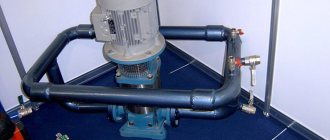
This unit is a modernized centrifugal pump, or rather its housing, which will serve as a stator. You can’t do without a working chamber and pipes.
Inside the body of our hydrodynamic design there is a flywheel as an impeller. There is a huge variety of rotary heat generator designs. The simplest among them is the disk design.
The required number of holes, which must have a certain diameter and depth, are applied to the cylindrical surface of the rotor disk. They are commonly called "Griggs cells". It is worth noting that the size and number of drilled holes will vary depending on the caliber of the rotor disk and the speed of the electric motor shaft.
The body of such a heat source is most often made in the form of a hollow cylinder. In essence, it is an ordinary pipe with welded flanges at the ends. The gap between the inside of the housing and the flywheel will be very small (approximately 1.5-2 mm).
Direct heating of water will occur precisely in this gap. Heating of the liquid is achieved due to its friction against the surface of the rotor and housing at the same time, while the flywheel disk moves at almost maximum speeds.
Cavitation (bubble formation) processes that occur in rotor cells have a great influence on the heating of the liquid.
A rotary heat generator is a modernized centrifugal pump, or rather its housing, which will serve as a stator
As a rule, the diameter of the disk in this type of heat generator is 300 mm, and the rotation speed of the hydraulic device is 3200 rpm. Depending on the size of the rotor, the rotation speed will vary.
Analyzing the design of this installation, we can conclude that its operating life is quite short. Due to the constant heating and abrasive action of water, the gap gradually expands.
Disadvantages and advantages
Let's consider the positive characteristics and advantages of induction equipment:
- Heating is carried out in any environment.
- Possibility of producing ultra-pure alloys.
- Rapid heating and melting of any material that conducts current.
- The elements of the device are mounted externally, there are no inserts. This ensures that there are no leaks.
- The induction water heater does not pollute the environment.
- Convenient when it is necessary to heat a certain area of the surface.
- The contact area of the coolant with the surface of the heater is many times larger than in devices with tubular electric heaters. Due to this, the environment heats up very quickly.
- Compact dimensions of the device.
- The equipment is easily configured to the desired operating mode and is easily adjusted.
- It is possible to manufacture a device of any shape (including independently). This prevents local heating and promotes uniform heat distribution.
A simple induction-type heater.
A flow-through heater of this type has practically no disadvantages when compared with devices operating on other principles. The only operational difficulty is that it is necessary to match the inductor with the workpiece. Otherwise, the heating will be insufficient and low-power.
Description of the generator
There are different types of vortex heat generators; they are mainly distinguished by their shape. Previously, only tubular models were used; now round, asymmetrical or oval ones are actively used. It should be noted that this small device can provide completely autonomous heating, and with the right approach, also hot water supply.
A vortex and hydro-vortex heat generator is a mechanical device that separates compressed gas from hot and cold streams. The air coming out of the “hot” end can reach a temperature of 200 ° C, and from the cold end it can reach -50. It should be noted that the main advantage of such a generator is that this electrical device has no moving parts, everything is permanently fixed. Pipes are most often made of stainless alloy steel, which perfectly withstands high temperatures and external destructive factors (pressure, corrosion, shock loads).
The compressed gas is blown tangentially into the vortex chamber, after which it is accelerated to a high rotation speed. Due to the conical nozzle at the end of the outlet pipe, only the "incoming" portion of the compressed gas is allowed to flow in a given direction. The rest is forced to return to the internal vortex, which is smaller in diameter than the outer one.
Where are vortex heat generators used:
- In refrigeration units;
- To provide heating for residential buildings;
- For heating industrial premises;
It must be taken into account that the vortex gas and hydraulic generator has lower efficiency than traditional air conditioning equipment. They are widely used for low-cost spot cooling when compressed air from a local heating network is available.
Video: studying vortex heat generators
The idea of creation
What to do if you don’t have enough money to purchase a heat generator? How to make it yourself? I will tell you about my own experience in this matter.
We got the idea to make our own heat generator after getting acquainted with various types of heat generators. Their designs seemed quite simple, but not fully thought out.
There are two known designs of such devices: rotary and static. In the first case, as you can guess from the name, a rotor is used to create cavitation; in the second, the main element of the device is the nozzle. To make a choice in favor of one of the design options, let’s compare both designs.
Price overview
Despite their relative simplicity, it is often easier to buy vortex cavitation heat generators than to assemble a homemade device yourself. Sales of new generation generators are carried out in many large cities of Russia, Ukraine, Belarus and Kazakhstan.
Let's look at the price list from open sources (mini-devices will be cheaper), how much the Mustafaev, Bolotov and Potapov generator costs:
The lowest price for a vortex energy heat generator of the brands Akoil, Vita, Graviton, Must, Euroalliance, Yusmar, NTK, in Izhevsk, for example, is about 700,000 rubles. When purchasing, be sure to check the device passport and quality certificates.
The purpose of the Potapov vortex heat generator (VTG), made by yourself, is to obtain heat only with the help of an electric motor and a pump. This device is mainly used as an economical heater.
Scheme of the vortex thermal system.
The easiest way is to make a vortex heat generator from standard parts. Any electric motor will do this. The more powerful it is, the larger volume of water it will heat to a given temperature.
Insulation of a vortex engine
Before putting the device into operation, it should be insulated. This is done after constructing the casing. It is recommended to wrap the structure with thermal insulation. As a rule, high-temperature resistant material is used for these purposes. The insulation layer is attached to the device casing with wire. One of the following materials should be used as thermal insulation:
Ready thermal generator.
- glass wool;
- mineral wool;
- basalt wool.
As you can see from the list, almost any fiber insulation will do. A vortex induction heater, reviews of which can be found all over the Russian Internet, must be insulated with high quality. Otherwise, there is a risk that the device will give off more heat to the room where it is installed. Good to know: “Insulation of pipelines with mineral wool.”
What features are endowed with long-burning wood stoves in this article.
Finally, some advice should be given. First, it is recommended to paint the surface of the product. This will protect it from corrosion. Secondly, it is advisable to make all the internal elements of the device thicker. This approach will increase their wear resistance and resistance to aggressive environments. Third, it’s worth making several spare caps. They must also have holes on the plane of the required diameter in the required places. This is necessary in order to achieve a higher efficiency of the unit through selection.
Tips you should listen to
Diagram of a heat gun.
- Be sure to protect the Potapov vortex heat generator by painting all surfaces.
- During operation, its internal parts will be in a very aggressive environment caused by cavitation processes. Therefore, try to make both the body and everything that is in it from thick material. Don't skimp on hardware.
- Make several versions of lids with different inlet holes. Then it will be easier to select their diameter in order to obtain high performance.
- The same applies to the vibration damper. It can also be modified.
Build a small laboratory stand where you will test all the characteristics. To do this, do not connect consumers, but loop the pipeline to the generator. This will simplify its testing and selection of the necessary parameters. Since complex instruments for determining the efficiency factor at home can hardly be found, the following test is proposed.
Turn on the vortex heat generator and note the time when it heats the water to a certain temperature. It is better to have an electronic thermometer, it is more accurate. Then make changes to the design and run the experiment again, monitoring the temperature increase. The more the water heats up at the same time, the more preference will need to be given to the final version of the installed improvement in the design.
Ways to Improve Productivity
Heat pump diagram.
Heat loss occurs in the pump. So Potapov’s vortex heat generator in this version has a significant drawback. Therefore, it is logical to surround the submerged pump with a water jacket so that its heat is also used for useful heating.
Make the outer casing of the entire device slightly larger than the diameter of the existing pump. This can be either a finished pipe, which is desirable, or a parallelepiped made from sheet material. Its dimensions must be such that the pump, coupling and the generator itself fit inside. The thickness of the walls must withstand the pressure in the system.
To reduce heat loss, install thermal insulation around the device body. It can be protected with a casing made of tin. As an insulator, use any thermal insulation material that can withstand the boiling point of the liquid.
- Assemble a compact device consisting of a submersible pump, a connecting pipe and a heat generator that you assembled with your own hands.
- Decide on its dimensions and select a pipe of a diameter that will easily accommodate all these mechanisms.
- Make covers on one side and the other.
- Ensure the rigidity of the internal mechanisms and the ability of the pump to pump water through itself from the resulting reservoir.
- Make an inlet hole and attach the pipe to it. The pump should be located inside with its water intake as close as possible to this hole.
Weld a flange on the opposite end of the pipe. With its help the cover will be attached through a rubber gasket. To make it easier to mount the insides, make a simple, lightweight frame or skeleton. Assemble the device inside it. Check the fit and tightness of all components. Insert into the housing and close the lid.
Connect to consumers and check everything for leaks. If there are no leaks, turn on the pump. By opening and closing the valve located at the outlet of the generator, adjust the temperature.
Device Security
To increase the safety of a homemade heater, the following requirements must be met:
- Organize high-quality insulation. All conductors and connections must be carefully insulated to eliminate the risk of electric shock.
- Choose the right heating system. Induction systems are not suitable for use with equipment that uses the principle of natural water circulation. These systems require a water pump.
- Select a suitable device location. The device should be located at a distance of 40 cm from walls and interior items, and at a distance of 80 cm from the ceiling or floor covering.
- Install control valves and pressure gauges. Such safety features will protect equipment from pressure surges. In addition, it is necessary to provide an air bleed system.
Vortex induction heaters - operating principle
Eddy induction heaters operate on the basis of the physical law that eddy currents arising (induced) by an alternating magnetic field heat the environment.
In theory. The hollow electromagnetic core with the induction coil is protected by a shielding shell from environmental influences. When voltage is applied through the terminal box, an alternating magnetic field is created, inducing eddy currents in the core coil, which leads to heating of the metal systems of the heat exchange system. Heat enters the coolant circulation system, heating it. The temperature is set using a thermostat, and the thermostat automatically maintains the set temperature.
On practice. Vortex induction heaters are a tube wrapped in wire that is supplied with alternating current. Cold coolant enters the pipe, usually from below, but also from the side. Eddy currents, which are created by alternating current in the wires wrapped around the pipe, heat the pipe, and, consequently, heat the water.
Homemade heater device
It is recommended to consider a classic induction device using the example of a water heater design for a heating system. Such schemes are most often used in dachas and country houses. The manufacture of the device begins with an inductor. To do this, copper wire must be wound in one row, giving it an initially cylindrical shape. Each turn is isolated from its neighbor, eliminating contacts between them.
The number of turns that ensures normal operation is on average 80-100. Copper conductors can have different cross-sections - from 2.5 to 4 mm2. The core is the heating pipe itself, but in practice this option does not give the desired effect.
Therefore, in order to make the heating of the coolant more intense, it is recommended to use a plastic pipe of a certain length. Its internal space is filled with steel wire D 5-6 mm, cut into short pieces. In this case, due to induction, the wire flowing around the water begins to heat up. The heat exchange area increases significantly, and the coolant heats up much faster. To prevent the wire cuttings from being washed away by the water flow, the ends of the pipe section are limited by protection made of steel mesh.
The connection between the inductor and the inverter can be done in different ways. Some specialists make an additional intermediate transformer. Then an inductor along with a capacitor is connected to its secondary winding. In another embodiment, a copper wire in the amount of one turn is wound onto a high-frequency toroidal transformer present in the inverter. Next, an inductor is directly connected to it.
In all cases, you cannot use the positive and negative terminals of the inverter intended for welding. Their output is rectified voltage, which is accompanied by high-frequency pulsations. Under its influence, a working magnetic field will not appear, and the inductor will overheat and burn out. The inverter will have to be redone, which in itself is quite difficult, since knowledge and skills in working with radio-electronic circuits will be needed.

